RU126113U1 - ARMOR MODULE (OPTIONS) AND ARMOR ELEMENT - Google Patents
ARMOR MODULE (OPTIONS) AND ARMOR ELEMENT Download PDFInfo
- Publication number
- RU126113U1 RU126113U1 RU2012123450/11U RU2012123450U RU126113U1 RU 126113 U1 RU126113 U1 RU 126113U1 RU 2012123450/11 U RU2012123450/11 U RU 2012123450/11U RU 2012123450 U RU2012123450 U RU 2012123450U RU 126113 U1 RU126113 U1 RU 126113U1
- Authority
- RU
- Russia
- Prior art keywords
- armor
- module
- claws
- module according
- housing
- Prior art date
Links
- 239000000463 material Substances 0.000 claims abstract description 56
- 239000002346 layers by function Substances 0.000 claims abstract description 25
- 239000002861 polymer material Substances 0.000 claims abstract description 19
- 239000010410 layer Substances 0.000 claims abstract description 14
- 238000009434 installation Methods 0.000 claims abstract description 8
- 210000000078 claw Anatomy 0.000 claims description 75
- 239000003292 glue Substances 0.000 claims description 7
- 230000002093 peripheral effect Effects 0.000 claims description 2
- 239000011248 coating agent Substances 0.000 description 13
- 238000000576 coating method Methods 0.000 description 13
- 239000006260 foam Substances 0.000 description 8
- 238000002474 experimental method Methods 0.000 description 7
- 239000002360 explosive Substances 0.000 description 7
- 230000007246 mechanism Effects 0.000 description 7
- 238000006386 neutralization reaction Methods 0.000 description 7
- 230000035515 penetration Effects 0.000 description 6
- 239000007858 starting material Substances 0.000 description 5
- 230000015572 biosynthetic process Effects 0.000 description 4
- 238000007373 indentation Methods 0.000 description 4
- 229920006328 Styrofoam Polymers 0.000 description 3
- 230000006835 compression Effects 0.000 description 3
- 238000007906 compression Methods 0.000 description 3
- 239000004020 conductor Substances 0.000 description 3
- 230000000694 effects Effects 0.000 description 3
- 230000003993 interaction Effects 0.000 description 3
- 230000000149 penetrating effect Effects 0.000 description 3
- -1 polyethylene Polymers 0.000 description 3
- 239000007787 solid Substances 0.000 description 3
- 239000008261 styrofoam Substances 0.000 description 3
- VGGSQFUCUMXWEO-UHFFFAOYSA-N Ethene Chemical compound C=C VGGSQFUCUMXWEO-UHFFFAOYSA-N 0.000 description 2
- 239000005977 Ethylene Substances 0.000 description 2
- 239000004698 Polyethylene Substances 0.000 description 2
- XTXRWKRVRITETP-UHFFFAOYSA-N Vinyl acetate Chemical compound CC(=O)OC=C XTXRWKRVRITETP-UHFFFAOYSA-N 0.000 description 2
- 230000001413 cellular effect Effects 0.000 description 2
- 230000008859 change Effects 0.000 description 2
- 229920001577 copolymer Polymers 0.000 description 2
- 229920001971 elastomer Polymers 0.000 description 2
- 239000007788 liquid Substances 0.000 description 2
- 239000011159 matrix material Substances 0.000 description 2
- 239000013518 molded foam Substances 0.000 description 2
- 229920000573 polyethylene Polymers 0.000 description 2
- 239000011148 porous material Substances 0.000 description 2
- 238000000926 separation method Methods 0.000 description 2
- 230000035939 shock Effects 0.000 description 2
- XLYOFNOQVPJJNP-UHFFFAOYSA-N water Substances O XLYOFNOQVPJJNP-UHFFFAOYSA-N 0.000 description 2
- 229920000742 Cotton Polymers 0.000 description 1
- 235000015842 Hesperis Nutrition 0.000 description 1
- 235000012633 Iberis amara Nutrition 0.000 description 1
- 206010024453 Ligament sprain Diseases 0.000 description 1
- 239000004952 Polyamide Substances 0.000 description 1
- 239000004793 Polystyrene Substances 0.000 description 1
- 208000010040 Sprains and Strains Diseases 0.000 description 1
- 229910000831 Steel Inorganic materials 0.000 description 1
- 230000009471 action Effects 0.000 description 1
- 239000000853 adhesive Substances 0.000 description 1
- 230000001070 adhesive effect Effects 0.000 description 1
- 239000002390 adhesive tape Substances 0.000 description 1
- 239000000969 carrier Substances 0.000 description 1
- 230000001066 destructive effect Effects 0.000 description 1
- 230000009977 dual effect Effects 0.000 description 1
- 238000004880 explosion Methods 0.000 description 1
- 238000010304 firing Methods 0.000 description 1
- 238000004519 manufacturing process Methods 0.000 description 1
- 230000004048 modification Effects 0.000 description 1
- 238000012986 modification Methods 0.000 description 1
- 230000003472 neutralizing effect Effects 0.000 description 1
- 229920002647 polyamide Polymers 0.000 description 1
- 229920002223 polystyrene Polymers 0.000 description 1
- 229920002635 polyurethane Polymers 0.000 description 1
- 239000004814 polyurethane Substances 0.000 description 1
- 230000001681 protective effect Effects 0.000 description 1
- 230000005855 radiation Effects 0.000 description 1
- 239000002356 single layer Substances 0.000 description 1
- 239000010959 steel Substances 0.000 description 1
- 239000000725 suspension Substances 0.000 description 1
- 239000012209 synthetic fiber Substances 0.000 description 1
- 229920002994 synthetic fiber Polymers 0.000 description 1
- 230000007704 transition Effects 0.000 description 1
Images


Classifications
-
- F—MECHANICAL ENGINEERING; LIGHTING; HEATING; WEAPONS; BLASTING
- F41—WEAPONS
- F41H—ARMOUR; ARMOURED TURRETS; ARMOURED OR ARMED VEHICLES; MEANS OF ATTACK OR DEFENCE, e.g. CAMOUFLAGE, IN GENERAL
- F41H5/00—Armour; Armour plates
- F41H5/02—Plate construction
-
- F—MECHANICAL ENGINEERING; LIGHTING; HEATING; WEAPONS; BLASTING
- F41—WEAPONS
- F41H—ARMOUR; ARMOURED TURRETS; ARMOURED OR ARMED VEHICLES; MEANS OF ATTACK OR DEFENCE, e.g. CAMOUFLAGE, IN GENERAL
- F41H5/00—Armour; Armour plates
- F41H5/02—Plate construction
- F41H5/023—Armour plate, or auxiliary armour plate mounted at a distance of the main armour plate, having cavities at its outer impact surface, or holes, for deflecting the projectile
- F41H5/026—Slat armour; Nets
-
- F—MECHANICAL ENGINEERING; LIGHTING; HEATING; WEAPONS; BLASTING
- F41—WEAPONS
- F41H—ARMOUR; ARMOURED TURRETS; ARMOURED OR ARMED VEHICLES; MEANS OF ATTACK OR DEFENCE, e.g. CAMOUFLAGE, IN GENERAL
- F41H5/00—Armour; Armour plates
- F41H5/02—Plate construction
- F41H5/04—Plate construction composed of more than one layer
- F41H5/0492—Layered armour containing hard elements, e.g. plates, spheres, rods, separated from each other, the elements being connected to a further flexible layer or being embedded in a plastics or an elastomer matrix
-
- F—MECHANICAL ENGINEERING; LIGHTING; HEATING; WEAPONS; BLASTING
- F41—WEAPONS
- F41H—ARMOUR; ARMOURED TURRETS; ARMOURED OR ARMED VEHICLES; MEANS OF ATTACK OR DEFENCE, e.g. CAMOUFLAGE, IN GENERAL
- F41H5/00—Armour; Armour plates
- F41H5/24—Armour; Armour plates for stationary use, e.g. fortifications ; Shelters; Guard Booths
-
- F—MECHANICAL ENGINEERING; LIGHTING; HEATING; WEAPONS; BLASTING
- F41—WEAPONS
- F41H—ARMOUR; ARMOURED TURRETS; ARMOURED OR ARMED VEHICLES; MEANS OF ATTACK OR DEFENCE, e.g. CAMOUFLAGE, IN GENERAL
- F41H7/00—Armoured or armed vehicles
Abstract
1. Вынесенный броневой модуль для установки на подлежащем защите корпусе, содержащий, по меньшей мере:- переднюю часть, которая содержит пригодный для контурного вырезания полимерный материал с элементами брони, расположенными в посадочных гнездах, выполненных в этом переднем материале путем резки или контурного вырезания, при этом элементы брони образуют функциональный броневой слой броневого модуля, и- заднюю часть, которая также содержит пригодный для контурного вырезания полимерный материал и имеет задний конец, сконфигурированный так, что он обращен к подлежащему защите корпусу при установке на нем модуля, причем задняя часть обеспечивает отступ между функциональным слоем и корпусом.2. Броневой модуль по п.1, отличающийся тем, что плотность пригодного для контурного вырезания полимерного материала составляет ниже 30% плотности элементов брони.3. Броневой модуль по п.2, отличающийся тем, что плотность материала не превышает 250 кг/м.4. Броневой модуль по п.1, отличающийся тем, что задний конец задней части выполнен с возможностью контурного вырезания до желаемой формы для установки на корпусе.5. Броневой модуль по п.1, отличающийся тем, что броневой модуль дополнительно содержит покрывающую деталь, выполненную с возможностью покрытия передней и/или задней части.6. Броневой модуль по п.5, отличающийся тем, что покрывающая деталь изготовлена из стойкого к вандализму материала.7. Броневой модуль по п.1, отличающийся тем, что задняя часть изготовлена из того же материала, что и материал передней части.8. Броневой модуль по п.7, отличающийся тем, что задняя часть и передняя часть выполнены в виде единого тела.9. Броневой м1. A remote armored module for installation on the housing to be protected, comprising at least: - a front part that contains polymer material suitable for contour cutting with armor elements located in landing slots made in this front material by cutting or contour cutting, while the armor elements form a functional armor layer of the armor module, and the back, which also contains suitable for contour cutting polymer material and has a rear end configured so that it faces the housing to be protected when a module is installed on it, with the back providing an indent between the functional layer and the housing. 2. The armor module according to claim 1, characterized in that the density of the polymer material suitable for contour cutting is below 30% of the density of the armor elements. The armored module according to claim 2, characterized in that the density of the material does not exceed 250 kg / m. 4. The armored module according to claim 1, characterized in that the rear end of the rear part is made with the possibility of contour cutting to the desired shape for installation on the body. The armored module according to claim 1, characterized in that the armored module further comprises a covering part configured to cover the front and / or rear. The armored module according to claim 5, characterized in that the covering part is made of a material resistant to vandalism. The armored module according to claim 1, characterized in that the rear part is made of the same material as the material of the front part. The armor module according to claim 7, characterized in that the rear part and the front part are made in the form of a single body. Armored m
Description
Область техники, к которой относится полезная модельThe technical field to which the utility model relates.
Полезная модель относится к броневым системам, в частности к броневым модулям для защиты транспортных средств и сооружений.The utility model relates to armored systems, in particular to armored modules for the protection of vehicles and structures.
Уровень техникиState of the art
Системы броневой защиты транспортных средств включают средства для выдерживания ударов шрапнели, пуль, ракет или снарядов и/или для нейтрализации механизмов срабатывания средств нападения, таких как реактивные гранаты (RPG-rocket-propelled grenade - граната на ракетной тяге). Этими системами защиты оснащаются транспортные средства, такие как танки, бронетранспортеры, самолеты и суда, однако они могут использоваться также для защиты стационарных сооружений, таких как сторожевые вышки вокруг военных баз, армейские посты и другие сооружения.Vehicle armor protection systems include means to withstand shrapnel, bullets, missiles or shells and / or to neutralize the mechanisms of the attack means, such as rocket-propelled grenade (RPG-rocket-propelled grenade). These protection systems equip vehicles, such as tanks, armored personnel carriers, aircraft and ships, but they can also be used to protect stationary structures, such as watch towers around military bases, army posts and other structures.
Типовая защитная система содержит плиты из материала, предназначенного для частичного поглощения удара, и/или элементы, конфигурация которых позволяет изменять траекторию снаряда и/или нейтрализовать механизм срабатывания снаряда. Однако эти плиты часто бывают очень тяжелыми.A typical protective system contains slabs of material intended to partially absorb shock, and / or elements, the configuration of which allows you to change the trajectory of the projectile and / or neutralize the mechanism of the projectile. However, these plates are often very heavy.
Одним из примеров обычного вооружения, используемого против транспортных средств, является реактивная граната, - запускаемая с плеча противотанковая боевая система, которая выпускает ракеты со взрывными боеголовками.One example of conventional weapons used against vehicles is a rocket-propelled grenade, an anti-tank combat system launched from the shoulder that fires rockets with explosive warheads.
На фиг.1 показан пример выполнения боеголовки 10 реактивной гранаты с электропроводным конусом 12, заключенным в аэродинамический колпак 13. Электрический пускатель 11, например, в виде пьезоэлектрического плавкого предохранителя, установлен на вершине аэродинамического колпака 13 и подсоединен к кромке электропроводного конуса 12. Боеголовка 10 содержит также тело 16, заполненное взрывчатым веществом 17, и проводник 18, электрически соединенный с электропроводным конусом 12. Тело 16 включает конический экран 14, который предназначен для фокусирования эффекта энергии взрывчатого вещества. Ракета 10 продвигается тягой двигателя, расположенного в хвостовой секции 19.Figure 1 shows an exemplary embodiment of a
Когда боеголовка ударяет в мишень, пускатель 11 выдает электрический сигнал, передаваемый через электропроводный конус 12 проводнику 18, который инициирует взрыв взрывчатого вещества 17. Взрывчатое вещество выходит к мишени через отверстие в коническом экране.When the warhead hits the target, the
Реечная броня, которая известна также под названием вынесенной брони, является типом брони, предназначенной для защиты от ударов реактивных гранат путем нейтрализации их механизмов взрывателей. Реечная броня включает жесткую решетку вокруг транспортного средства, которая нейтрализует боеголовку либо путем деформации конического экрана, либо путем короткого замыкания механизма взрывателя боеголовки. Реечная броня выполняется в виде жесткой решетки, расположенной на определенном расстоянии от транспортного средства, чтобы обеспечивать контакт брони с колпаком реактивной гранаты для ее нейтрализации до того, как пускатель ударит в тело транспортного средства. Расстояние между решеткой и телом транспортного средства называется отступом.Rack and pinion armor, also known as staked armor, is a type of armor designed to protect against grenade attacks by neutralizing their fuse mechanisms. The rack armor includes a rigid grille around the vehicle, which neutralizes the warhead either by deforming the conical screen or by short-circuiting the mechanism of the warhead fuse. The rack armor is made in the form of a rigid lattice located at a certain distance from the vehicle in order to ensure that the armor contacts the cap of the rocket-propelled grenade to neutralize it before the starter hits the body of the vehicle. The distance between the grill and the vehicle body is called indentation.
Согласно одному из примеров выполнения вынесенная броня включает гибкую сетку с жесткими элементами. Жесткие элементы отстоят друг от друга таким образом, что не допускают столкновения боеголовки реактивной гранаты с сеткой без контакта, по меньшей мере, с одним жестким элементом. При этом жесткий элемент нейтрализует разрушительное действие боеголовки путем деформации конического экрана и/или путем короткого замыкания механизма взрывателя.According to one exemplary embodiment, the made armor includes a flexible mesh with rigid elements. Rigid elements are spaced from each other in such a way that they prevent collision of the rocket-propelled grenade warhead with the net without contacting at least one rigid element. In this case, the rigid element neutralizes the destructive effect of the warhead by deforming the conical screen and / or by short-circuiting the fuse mechanism.
Далее, известна подвеска элементов брони внутри сети. В такой системе сеть обычно выполнена в виде решетки пересекающихся струн, а элементы брони прикреплены к струнам. Известно также крепление элементов брони к сети в узловых точках соединения струн.Further, the suspension of armor elements within the network is known. In such a system, the network is usually made in the form of a lattice of intersecting strings, and the armor elements are attached to the strings. It is also known to attach armor elements to the network at the nodal points of string connection.
Известно несколько примеров выполнения, в которых элементы брони работают во взаимодействии с сетью. Так например, элемент брони может содержать первую, сплошную часть и вторую часть, образованную множеством лепестков, которые отходят от сплошной части. В частности, элемент брони устанавливается на сети таким образом, что струны сети проходят между лепестками, облегчая включение элементов брони в сеть. Один из примеров такого элемента брони описан в патентном документе US 2011/0079135.There are several examples of execution in which the elements of the armor work in conjunction with the network. For example, the armor element may comprise a first, solid part and a second part formed by a plurality of petals that extend from the solid part. In particular, the armor element is installed on the network in such a way that the network strings pass between the petals, facilitating the inclusion of the armor elements in the network. One example of such an armor element is described in patent document US 2011/0079135.
Раскрытие полезной моделиUtility Model Disclosure
В соответствии с полезной моделью предусмотрен вынесенный броневой модуль для установки на подлежащем защите корпусе, содержащий переднюю часть, которая содержит пригодный для контурного вырезания полимерный материал с элементами брони, расположенными в посадочных гнездах, выполненных в этом переднем материале путем резки или контурного вырезания, при этом элементы брони образуют функциональный броневой слой броневого модуля, при этом броневой модуль далее содержит заднюю часть, которая также содержит пригодный для контурного вырезания полимерный материал и имеет задний конец, сконфигурированный так, что он обращен к подлежащему защите корпусу при установке на нем модуля, причем задняя часть обеспечивает отступ между функциональным слоем и корпусом, а задний конец задней части выполнен с возможностью контурного вырезания до желаемой формы для установки на корпусе.In accordance with a utility model, there is provided a remote armored module for mounting on a housing to be protected, comprising a front part that contains polymer material suitable for contour cutting with armor elements located in landing slots made in this front material by cutting or contour cutting, while the armor elements form a functional armor layer of the armor module, while the armor module further comprises a rear part, which also contains a contour cut suitable for polymer material and has a rear end configured so that it faces the housing to be protected when a module is installed on it, the rear part provides an indent between the functional layer and the housing, and the rear end of the rear part is capable of contour cutting to the desired shape for installation on the case.
Согласно другому аспекту полезной модели броневой модуль может содержать только функциональный слой, содержащий пригодный для контурного вырезания полимерный материал с элементами брони, расположенными в выполненных в нем посадочных гнездах, при этом функциональный слой расположен на расстоянии от подлежащего защите корпуса с образованием воздушного зазора между функциональным слоем и корпусом, представляющего отступ.According to another aspect of the utility model, the armor module may contain only a functional layer containing suitable for contour cutting polymer material with armor elements located in the seats made therein, while the functional layer is located at a distance from the body to be protected to form an air gap between the functional layer and a body representing an indent.
Пригодный для контурного вырезания полимерный материал передней части и/или задней части может быть сохраняющим форму материалом, таким как ячеистый или пористый материал, в частности пенопласт. Плотность материала существенно ниже плотности элементов брони. В частности, плотность материала может быть ниже 50% плотности элементов брони, предпочтительно ниже 30% и особенно предпочтительно ниже 10%. В качестве примера величины плотности материала не превышают 250 кг/м3. Этот материал может быть, например, материалом из следующих групп: пенопласты с закрытыми ячейками, пеноматериалы EVA из сополимера этилена и винилацетата (ethylene and vinyl acetate - EVA) и формованные пенопласты. В качестве примера можно привести такие материалы как стирофом, полиэтиленовый пенопласт и т.д. Альтернативно полимерным материалом может быть материал на основе легкой резины.Suitable for contour cutting polymer material of the front and / or rear can be a shape-preserving material, such as cellular or porous material, in particular foam. The density of the material is significantly lower than the density of the elements of the armor. In particular, the density of the material may be below 50% of the density of the elements of the armor, preferably below 30%, and particularly preferably below 10%. As an example, the density of the material does not exceed 250 kg / m 3 . This material may be, for example, material from the following groups: closed cell foams, EVA foams of ethylene and vinyl acetate (EVA) copolymer, and molded foams. Examples include materials such as styrofoam, polyethylene foam, etc. Alternatively, the polymer material may be a light rubber based material.
Задняя часть может быть изготовлена из того же материала, что и материал передней части. Кроме того, задняя часть и передняя часть могут быть выполнены в виде единого тела. Далее, обе части или одна передняя или задняя часть могут содержать больше одного пригодного к контурному вырезанию полимерного материала. Передняя часть может быть прикреплена к задней части любыми подходящими средствами, например, клеем.The back can be made of the same material as the front. In addition, the rear part and the front part can be made in the form of a single body. Further, both parts or one front or rear part may contain more than one contourable polymer material. The front part can be attached to the rear part by any suitable means, for example, glue.
Если отступ между функциональным слоем и подлежащим защите корпусом не обеспечивается помещенной между ними задней частью, отступ может обеспечиваться опорной конструкцией, прикрепленной к подлежащему защите корпусу, а функциональный слой может быть прикреплен к ней или установлен на ней.If the indentation between the functional layer and the housing to be protected is not ensured by the rear portion placed between them, the indentation may be provided by the supporting structure attached to the housing to be protected, and the functional layer may be attached to or installed on it.
Согласно одному примеру осуществления опорная конструкция может быть выполнена в виде связей или стержней, которые проходят между функциональным слоем и подлежащим защите корпусом и предназначены для удержания функционального слоя с отступом. Конструкция может быть такой, что каждая из связей/стержней имеет первую точку, прикрепленную к подлежащему защите корпусу, и вторую точку, прикрепленную к функциональному слою.According to one embodiment, the support structure may be in the form of ties or rods that extend between the functional layer and the housing to be protected and are designed to hold the functional layer indented. The design may be such that each of the ties / rods has a first point attached to the body to be protected and a second point attached to the functional layer.
Согласно другому примеру осуществления функциональный слой может быть выполнен с возможностью перемещения вдоль связей/стержней для обеспечения возможности регулировки расстояния отступа. Так, например, связи/стержни могут быть снабжены направляющими, вдоль которых функциональный слой может перемещаться к подлежащему защите корпусу и от него. Альтернативно функциональный слой может быть снабжен элементами зацепления (например, кольцами, карабинами) для взаимодействия со связями/стержнями, навески на них и скольжения вдоль них.According to another embodiment, the functional layer may be movable along ties / rods to allow adjustment of the indent distance. For example, ties / rods may be provided with guides along which the functional layer can move to and from the housing to be protected. Alternatively, the functional layer may be provided with engagement elements (for example, rings, carabiners) for interacting with ties / rods, hanging on them and sliding along them.
Согласно частному примеру осуществления опорная конструкция может быть изготовлена из того же материала, что и материал передней части, и может иметь любую форму, подходящую для надежного удержания функционального слоя в желаемом положении. Очевидно, что опорная конструкция, изготовленная из того же материала, что и функциональный слой, может быть усилена дополнительными конструктивными элементами (например, жесткими внутренними стержнями/связями) для лучшего поддержания функционального слоя.According to a particular embodiment, the support structure may be made of the same material as the material of the front part, and may have any shape suitable for reliably holding the functional layer in the desired position. Obviously, a support structure made of the same material as the functional layer can be reinforced with additional structural elements (for example, rigid inner rods / ties) to better maintain the functional layer.
Элементы брони могут быть посажены в материале передней части с помощью клея или без него. Передняя часть может содержать слой со сквозными отверстиями, в которых удерживаются элементы брони, причем отверстия вырезаны в материале передней части. Альтернативно посадочные гнезда могут быть выполнены в виде глухих выемок или, в том случае, когда полимерный материал передней части эластичен, элементы брони могут быть расположены в щелях, образованных в материале передней части. При этом эластичность материала допускает расширение щелей для закладки в них элементов брони.Armor elements can be planted in the front material with or without glue. The front part may contain a layer with through holes in which the elements of the armor are held, and the holes are cut out in the material of the front part. Alternatively, the seating nests may be in the form of blind recesses or, in the case when the polymer material of the front part is elastic, the armor elements can be located in the slots formed in the material of the front part. At the same time, the elasticity of the material allows the expansion of slots for laying armor elements in them.
Благодаря пригодности материала передней части к контурному вырезанию формирование посадочных гнезд для элементов брони может выполняться с помощью простых режущих инструментов, таких как нож (универсальный профессиональный нож, нож Стенли, канцелярский нож, нож Х-Acto и др.).Due to the suitability of the material of the front part for contour cutting, the formation of landing seats for armor elements can be performed using simple cutting tools, such as a knife (universal professional knife, Stanley knife, stationery knife, X-Acto knife, etc.).
Элементы брони могут быть выполнены в форме таблеток, цилиндров, многоугольных тел, шаров или даже могут иметь произвольные формы. Элементы брони могут быть также электропроводными для короткого замыкания механизма взрывателя боеголовки, такой как реактивная граната.Elements of armor can be made in the form of tablets, cylinders, polygonal bodies, balls, or even can have arbitrary shapes. Armor elements may also be electrically conductive to short-circuit a warhead fuse mechanism, such as a rocket-propelled grenade.
Далее, броневой модуль может содержать покрывающий слой, предназначенный для крепления к переднему концу передней части для удержания на месте элементов брони.Further, the armor module may include a covering layer designed to be attached to the front end of the front part to hold in place the armor elements.
Броневой модуль может содержать покрытие, предназначенное для покрытия передней части и/или задней части с тем, чтобы удерживать блок внутри покрытия. Покрытие может также использоваться для удержания вместе передней и задней частей. Покрытие может быть изготовлено из водостойкого материала или из стойкого к вандализму материала, чтобы соответственно защищать модуль. Покрытие может быть выполнено в виде одной покрывающей детали или из нескольких покрывающих деталей, прикрепленных друг к другу или к передней/задней частям модуля. В любом случае покрытие может быть изготовлено из водостойкого материала и, по меньшей мере, его передняя часть может дополнительно иметь характеристики стойкости к вандализму.The armor module may include a coating designed to cover the front and / or rear so as to hold the unit inside the cover. The coating can also be used to hold the front and back parts together. The coating can be made of a waterproof material or of a material resistant to vandalism in order to protect the module accordingly. The coating can be made in the form of one covering part or from several covering parts attached to each other or to the front / rear parts of the module. In any case, the coating may be made of a waterproof material and at least its front part may additionally have vandalism resistance characteristics.
В другом аспекте полезной модели предложен элемент брони, предназначенный для использования в броневом модуле в соответствии с предыдущим аспектом, при этом элемент брони выполнен с образующей основание частью и образующей лапу частью, при этом образующая лапу часть содержит два или большее число когтей, отходящих от образующей основание части, при этом каждый коготь имеет задний конец, связанный с образующей основание частью, и передний конец, отстоящий от образующей основание части, при этом расстояние между соответствующими передними концами двух или большего числа когтей больше расстояния между задними концами двух или большего числа когтей.In another aspect of the utility model, an armor element is provided for use in an armor module in accordance with the previous aspect, wherein the armor element is provided with a base forming part and a paw forming part, wherein the paw forming part contains two or more claws extending from the generating the base of the part, with each claw having a rear end connected to the forming part of the base, and a front end spaced from the forming part of the base, while the distance between the corresponding front and the ends of two or more claws are greater than the distance between the rear ends of two or more claws.
Образующая основание часть может быть вписана в окружность с центром в точке О, а центральная ось X может определяться как ось, проходящая через точку О перпендикулярно плоскости, определенной описанной окружностью.The part forming the base can be inscribed in a circle centered at point O, and the central axis X can be defined as the axis passing through point O perpendicular to the plane defined by the circumscribed circle.
В частности, конструкция может быть такой, что когти расположены под углом друг к другу для образования образующей лапу части с углом конусности относительно образующей основание части. Дополнительно, по меньшей мере, некоторые из когтей могут определять описанный конус, центральная ось которого лежит на одной прямой с центральной осью X, при этом угол при вершине конуса определяется углом конусности образующей лапу части. Благодаря углу конусности поперечное сечение конуса, удаленное от образующей лапу части и связанное с передними концами когтей, имеет больший диаметр, чем поперечное сечение конуса непосредственно вблизи образующей лапу части, связанное с задними концами когтей.In particular, the structure may be such that the claws are angled to each other to form a paw-forming part with a taper angle relative to the base-forming part. Additionally, at least some of the claws can define the described cone, the central axis of which lies on a straight line with the central axis X, while the angle at the apex of the cone is determined by the cone angle of the part forming the paw. Due to the taper angle, the cross section of the cone, remote from the claw forming part and connected with the front ends of the claws, has a larger diameter than the cross section of the cone directly near the claw forming part, connected with the rear ends of the claws.
Согласно частному примеру выполнения образующая лапу часть может содержать несколько комплектов когтей, при этом каждый комплект определяет индивидуальный описанный конус, имеющий собственный угол при вершине конуса.According to a particular embodiment, the paw forming part may contain several sets of claws, each set defining an individual described cone having its own angle at the apex of the cone.
Когти образующей лапу части предназначены для проникновения в снаряд при столкновении с ним. Поэтому угол конусности должен быть выбран таким, чтобы при столкновении со снарядом когти имели достаточную опору со стороны образующей основание части вдоль направления центральной оси. При этом при столкновении со снарядом наружная поверхность снаряда поддастся воздействию первой (то есть будет пронизана).The claws of the paw-forming part are intended to penetrate the projectile in a collision with it. Therefore, the angle of taper should be chosen so that in a collision with the projectile the claws have sufficient support from the side forming the base of the part along the direction of the central axis. In this case, in a collision with a projectile, the outer surface of the projectile will succumb to the first (that is, it will be pierced).
Конкретно угол между каждым когтем и центральной осью может быть выбран не более 50°, предпочтительно не более 40°, более предпочтительно не более 30°, еще предпочтительнее не более 20° и особенно предпочтительно не более 10°. Соответственно, угол конусности между двумя или большим числом когтей (то есть угол при вершине конуса) может быть выбран не более 100°, предпочтительно не более 80°, более предпочтительно не более 60°, еще предпочтительнее не более 40° и особенно предпочтительно не более 20°.Specifically, the angle between each claw and the central axis can be selected no more than 50 °, preferably no more than 40 °, more preferably no more than 30 °, even more preferably no more than 20 °, and particularly preferably no more than 10 °. Accordingly, the taper angle between two or more claws (i.e., the angle at the apex of the cone) can be selected no more than 100 °, preferably not more than 80 °, more preferably not more than 60 °, even more preferably not more than 40 ° and especially preferably not more 20 °.
Другие доводы относительно угла конусности будут рассмотрены впоследствии в связи с действием элементов брони во время столкновения со снарядом.Other arguments regarding the taper angle will be considered subsequently in connection with the action of the elements of the armor during a collision with a projectile.
Дополнительно когти могут быть расположены симметрично вокруг центральной оси X, то есть равномерно разнесены вокруг центральной оси X. В том случае, когда образующая лапу часть содержит несколько комплектов когтей, когти, по меньшей мере, одного комплекта могут быть равномерно разнесены вокруг центральной оси X.Additionally, the claws can be symmetrically arranged around the central axis X, that is, evenly spaced around the central axis X. In the case where the part forming the paw contains several sets of claws, the claws of at least one set can be uniformly spaced around the central axis X.
Каждый из когтей может быть выполнен с множеством кромок, способствующих более эффективному проникновению в снаряд. В частности, каждый коготь может определяться поверхностями (криволинейными или плоскими), а кромки образованы на пересечениях между двумя или большим числом этих поверхностей.Each of the claws can be made with many edges, contributing to a more efficient penetration into the projectile. In particular, each claw can be defined by surfaces (curved or flat), and the edges are formed at the intersections between two or more of these surfaces.
Любой из когтей может иметь по существу форму призмы. Конкретно каждый такой коготь может быть образован с любой одной из следующих поверхностей: Any of the claws can be essentially prismatic. Specifically, each such claw can be formed from any one of the following surfaces:
- наружная поверхность, связанная с указанным описанным конусом и проходящая по окружной периферии когтя;- the outer surface associated with the specified described cone and passing along the peripheral periphery of the claw;
- одна или большее число боковых поверхностей, проходящих по существу радиально от наружной поверхности к центральной оси: иone or more side surfaces extending substantially radially from the outer surface to the central axis: and
- передняя поверхность, связанная с передним концом когтя, проходящая между боковыми поверхностями и наружной поверхностью.- the front surface associated with the front end of the claw, passing between the side surfaces and the outer surface.
Коготь может быть выполнен так, что, по меньшей мере, передний конец когтя образован, по меньшей мере, одной кромкой, которая лежит в плоскости, по существу перпендикулярной центральной оси элемента брони. Следует отметить, что наличие такой передней кромки может способствовать увеличению ожидаемого поверхностного контакта между элементом брони и наружной поверхностью снаряда (в противоположность когтям заостренной конфигурации).The claw may be configured such that at least the front end of the claw is formed by at least one edge that lies in a plane substantially perpendicular to the central axis of the armor element. It should be noted that the presence of such a leading edge can increase the expected surface contact between the armor element and the outer surface of the projectile (as opposed to the claws of the pointed configuration).
Передняя поверхность когтя может быть наклонной как относительно центральной оси, так и к наружной и/или боковым поверхностям. В частности, передняя поверхность может иметь такой наклон, что кромка, которую она образует с наружной поверхностью, является кромкой передней поверхности, наиболее удаленной от образующей основание части.The front surface of the claw can be inclined both relative to the central axis and to the outer and / or side surfaces. In particular, the front surface may have such a slope that the edge that it forms with the outer surface is the edge of the front surface farthest from the base forming part.
Когда два или большее число когтей образованы с такой передней поверхностью, дополнительный угол конусности может быть определен между их соответствующими передними поверхностями, при этом дополнительный угол конусности больше угла конусности между когтями.When two or more claws are formed with such a front surface, an additional taper angle can be defined between their respective front surfaces, with an additional taper angle greater than the taper angle between the claws.
Конкретно дополнительный угол конусности не может быть больше 120°, предпочтительно не больше 100°, более предпочтительно не больше 80°, еще более предпочтительно не больше 60° и особенно предпочтительно не больше 40°.Specifically, the additional taper angle cannot be greater than 120 °, preferably not more than 100 °, more preferably not more than 80 °, even more preferably not more than 60 °, and particularly preferably not more than 40 °.
Согласно конкретному примеру осуществления коготь может быть выполнен в виде треугольной призмы, имеющей криволинейную наружную поверхность, две боковые поверхности, расположенные под углом друг к другу для образования треугольной формы призмы, и переднюю поверхность, примыкающую как к наружной поверхности, так и к боковым поверхностям. При такой конфигурации угол наклона может быть около 10°, а дополнительный угол конусности может быть около 90°.According to a specific embodiment, the claw can be made in the form of a triangular prism having a curved outer surface, two side surfaces located at an angle to each other to form a triangular prism, and a front surface adjacent to both the outer surface and the side surfaces. With this configuration, the tilt angle can be about 10 °, and the additional taper angle can be about 90 °.
Образующая основание часть может иметь форму многоугольной призмы, то есть иметь прямоугольное, квадратное, треугольное, шестиугольное или даже круглое поперечное сечение.The base-forming part may be in the form of a polygonal prism, that is, have a rectangular, square, triangular, hexagonal or even circular cross section.
В сборе с броневым модулем элемент брони может быть расположен таким образом, что его образующая основание часть обращена к подлежащему защите корпусу, а образующая лапу часть обращена к ожидаемому направлению приближающегося снаряда. В частности, элемент брони может быть расположен таким образом, что его центральная ось параллельна ожидаемому направлению удара.Assembled with the armored module, the armor element can be located in such a way that its base-forming part is facing the body to be protected, and the part forming the paw is facing the expected direction of the approaching projectile. In particular, the armor element can be positioned so that its central axis is parallel to the expected direction of impact.
Элемент брони может быть предназначен для установки в матрице броневого модуля, как это было описано в отношении первого предмета полезной модели. В этом случае элемент брони вставлен в пригодный к контурному вырезанию полимерный материал и удерживается в нем за счет трения с материалом.The armor element can be designed to be installed in the matrix of the armor module, as described in relation to the first subject of the utility model. In this case, the armor element is inserted into the polymeric material suitable for contour cutting and is held therein by friction with the material.
Альтернативно элемент брони может быть предназначен для установки в поверхности решетки, образованной из множества пересекающихся линий, образующих ячейки. В частности, элемент брони может быть выполнен таким, что его образующая основание часть несколько шире одной из таких ячеек, так что он может быть плотно вставлен в нее.Alternatively, the armor element may be designed to be mounted on the surface of a grating formed from a plurality of intersecting lines forming cells. In particular, the armor element can be made such that its part forming the base is somewhat wider than one of such cells, so that it can be tightly inserted into it.
При этом система может быть такой, что образующая основание часть вставлена в ячейку с плотной посадкой, а образующая лапу часть выступает от поверхности решетки в направлении приближающегося снаряда. В этом случае угол конусности образующей лапу части служит для выполнения дополнительной функции предотвращения высвобождения элемента брони путем прохода через ячейку решетки при ударе в него снаряда.In this case, the system may be such that the part forming the base is inserted into the cell with a tight fit, and the part forming the paw protrudes from the surface of the grating in the direction of the approaching projectile. In this case, the taper angle of the part forming the paw serves to perform the additional function of preventing the release of the armor element by passing through the lattice cell when a projectile hits it.
В конструкции броневого модуля обычно желательно, с одной стороны, по возможности уменьшить до минимума площадь элементов брони, чтобы снизить риск привода в действие взрывателя приближающегося снаряда, и с другой стороны, чтобы обеспечить проникновение, по меньшей мере, одного элемента брони в наружную поверхность снаряда.In the design of the armored module, it is usually desirable, on the one hand, to minimize the area of the armor elements, to reduce the risk of firing an approaching projectile, and on the other hand, to ensure that at least one armor element penetrates the outer surface of the shell .
Соответственно, угол конусности когтей элемента брони выбран таким, что образующая лапу часть не увеличивает значительно площадь элемента брони по сравнению с площадью, занимаемой образующей основание частью. Другими словами, диаметр DCLAW описанной окружности, определяемой передними концами когтей, не является значительно превышающим диаметр DBASE описанной окружности основания.Accordingly, the taper angle of the claws of the armor element is such that the part forming the paw does not significantly increase the area of the armor element compared to the area occupied by the part forming the base. In other words, the diameter D CLAW of the circumference defined by the front ends of the claws is not significantly greater than the diameter D BASE of the circumference of the base.
Отношение DCLAW/DBASE не может быть больше 2, предпочтительно оно составляет не больше 1,5, более предпочтительно не больше 1,2, еще более предпочтительно не больше 1,1 и особенно предпочтительно не больше 1,05.The ratio D CLAW / D BASE cannot be greater than 2, preferably it is not more than 1.5, more preferably not more than 1.2, even more preferably not more than 1.1, and particularly preferably not more than 1.05.
Несмотря на вышесказанное, при эксплуатации броневого модуля с описанными элементами брони одновременно желательно повысить шансы проникновения элемента брони в наружную поверхность снаряда. Следует понимать, что, с одной стороны, угол конусности должен быть достаточно малым, чтобы не увеличивать площадь элемента брони, а с другой стороны, он должен быть достаточно большим, чтобы предотвращать «скользящее касание/отражение» элемента брони от снаряда. В частности, угол конусности может снижать шансы того, что когти будут просто скользить вдоль снаряда и деформироваться радиально внутрь к центральной оси. В этом случае элемент брони может просто «погладить/отразиться» от наружной поверхности снаряда без достижения желаемого эффекта проникновения и нейтрализации.Despite the foregoing, when operating an armored module with the described armor elements, it is also desirable to simultaneously increase the chances of the armor element penetrating the outer surface of the projectile. It should be understood that, on the one hand, the taper angle should be small enough so as not to increase the area of the armor element, and on the other hand, it should be large enough to prevent the "sliding touch / reflection" of the armor element from the projectile. In particular, the taper angle can reduce the chances that the claws will simply slide along the projectile and deform radially inward to the central axis. In this case, the armor element can simply "stroke / reflect" from the outer surface of the projectile without achieving the desired effect of penetration and neutralization.
Краткий перечень чертежейBrief List of Drawings
Далее для пояснения предмета полезной модели и возможностей ее практического применения будут подробно описаны не являющиеся ограничительными примеры осуществления полезной модели со ссылками на прилагаемые чертежи. На чертежах:Next, to explain the subject of the utility model and the possibilities of its practical application, non-restrictive examples of the implementation of the utility model with reference to the accompanying drawings will be described in detail. In the drawings:
фиг.1 схематично изображает в перспективе с продольным разрезом известную из уровня техники реактивную гранату,figure 1 schematically depicts in perspective a longitudinal section of a known from the prior art rocket launcher,
фиг.2 изображает в перспективе сверху броневой модуль в соответствии с одним примером выполнения,figure 2 depicts a perspective view from above of an armored module in accordance with one exemplary embodiment,
фиг.2А схематично изображает в перспективе сверху броневой модуль в соответствии с другим примером выполнения,figa schematically depicts a perspective view from above of an armored module in accordance with another exemplary embodiment,
фиг.2В схематично изображает броневой модуль в разрезе в плоскости I-I на фиг.2А,figv schematically depicts an armored module in section in the plane I-I in figa,
фиг.2С схематично изображает в разрезе броневой модуль в следующем примере выполнения,figs schematically depicts a sectional armor module in the following example,
фиг.3А схематично изображает в перспективе функциональный слой броневого модуля по фиг.2,figa schematically depicts in perspective a functional layer of the armored module of figure 2,
фиг.3В схематично изображает в перспективе функциональный слой броневого модуля в следующем примере выполнения,figv schematically depicts in perspective a functional layer of an armored module in the following exemplary embodiment,
фиг.4А схематично изображает в продольном разрезе ракету реактивной гранаты по фиг.1 при ее нейтрализации броневым модулем по полезной модели,figa schematically depicts a longitudinal section of a rocket rocket grenade in figure 1 when it is neutralized by an armored module according to a utility model,
фиг.4В схематично изображает в увеличенном виде узел А на фиг.4А,figv schematically depicts an enlarged view of the node a in figa,
фиг.5A-5D схематично изображают в перспективе, на виде спереди, сзади и сбоку элемент брони, используемый в броневом модуле по любой из фиг.2-4В,figa-5D schematically depict a perspective view, in front, back and side view of the armor element used in the armor module according to any one of Fig.2-4B,
фиг.5Е схематично изображает вид в разрезе в плоскости А-А на фиг.5 В,5E schematically depicts a sectional view in the plane AA in FIG. 5B,
фиг.5F и 5G схематично изображают на виде спереди и сбоку элемент брони по фиг.5A-5D, встроенный в решетку,FIGS. 5F and 5G schematically depict front and side views of the armor element of FIGS. 5A-5D embedded in the grating,
фиг.6А-6Е представляют фото, показывающие последовательные этапы взаимодействия между элементом брони по фиг.5А-5Е и реактивным снарядом,figa-6E are photos showing the successive stages of interaction between the armor element of figa-5E and a missile,
фиг.7А и 7В представляют фото реактивного снаряда после повреждения элементом брони по фиг.5А-5Е, соответственно, на виде в перспективе и сбоку,figa and 7B are photos of a missile after damage by an armor element of figa-5E, respectively, in perspective view and side view,
фиг.7С представляет фото элемента брони по фиг.5А-5Е после удара реактивного снаряда.figs presents a photo of the armor element of figa-5E after hitting a missile.
Осуществление полезной моделиUtility Model Implementation
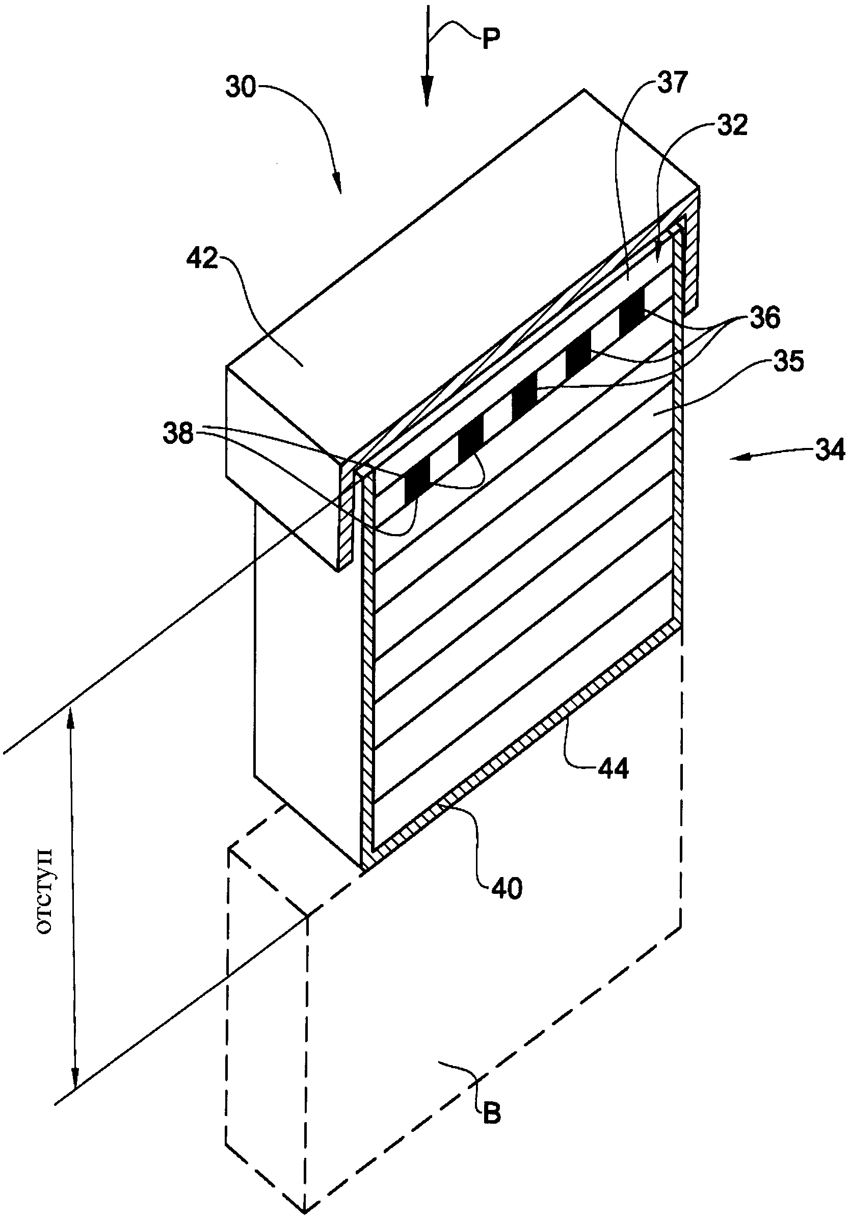
На фиг.2 показан в перспективе сверху броневой модуль, обозначенный в целом позицией 30 и содержащий переднюю часть 32 и заднюю часть 34. Передняя часть 32 изготовлена из пригодного для контурного вырезания полимерного материала с вставленным в него множеством элементов 36 брони и содержит покрывающий слой 37, предназначенный для покрытия переднего конца передней части и для предотвращения отделения элементов 36 брони. Задняя часть 34 создает отступ между элементами брони и подлежащим защите корпусом В.Figure 2 shows a perspective view from above of the armor module, generally indicated by 30 and containing the
Как передняя часть 32, так и задняя часть 34 изготовлены из полимерного материала, который может быть сохраняющим форму материалом, обеспечивающим удобство для формирования посадочных гнезд для элементов брони. Полимерный материал может быть ячеистым или пористым материалом, в частности пенопластом. Плотность материала существенно ниже плотности элементов брони. В частности, плотность материала может быть ниже 50%, предпочтительно ниже 30% и особенно предпочтительно ниже 10% плотности элементов брони. В качестве примера величины плотности материала не превышают 250 кг/м3. Этот материал может быть выбран, например, из следующих групп: пенопласты с закрытыми ячейками, пеноматериалы EVA из сополимера 'этилена и винилацетата (ethylene and vinyl acetate - EVA) и формованные пеноматериалы. В качестве примера можно привести такие материалы как полученный экструзией полистирен, стирофом, полиэтилен, пенопласт Palciv® и т.д. Альтернативно полимерным материалом может быть материал на основе легкой резины.Both the
В частности, материал, из которого изготовлена передняя часть, может иметь следующие характеристики:In particular, the material of which the front part is made may have the following characteristics:
Ширина задней части 34 определяет расстояние между передней частью 32 и корпусом транспортного средства, чтобы обеспечивать расстояние отступа между функциональным слоем и корпусом. Следует заметить, что задняя часть 34 может содержать один слой, по существу заполняющий зазор между передним слоем 32 и корпусом. Альтернативно задняя часть 34 может содержать больше одного слоя или множество слоев, отстоящих друг от друга. Согласно другому примеру выполнения задняя часть может содержать боковые стенки, на которых установлена передняя часть 32, с образованием пространства между передней стенкой 32 и корпусом транспортного средства.The width of the
Далее, задняя часть содержит задний конец 40, который обращен к подлежащему защите корпусу при установке на нем броневого модуля. Задний конец может быть вырезан в соответствии с любой желаемой формой для обеспечения возможности установки броневого модуля 30 на корпусе транспортного средства. Так например, задний конец 40 может иметь форму, соответствующую наружной форме корпуса транспортного средства, чтобы обеспечивать оптимальную защиту транспортного средства со всех сторон.Further, the rear part comprises a
Передняя часть 32 броневого модуля 30 покрыта первой покрывающей деталью 42, а задняя часть 34 может быть покрыта второй покрывающей деталью 44. Вторая покрывающая деталь 44 может быть изготовлена из материала, предназначенного для обеспечения стойкости к погодным условиям и водостойкости, а первая покрывающая деталь 42 может быть изготовлена из материала, который помимо стойкости к погодным условиям и водостойкости имеет характеристику защиты от вандализма.The
В качестве примера покрывающий материал может представлять собой комбинацию различных материалов в следующем процентном соотношении:As an example, the coating material may be a combination of various materials in the following percentage:
В броневом модуле по данному примеру выполнения вторая покрывающая деталь 44 охватывает переднюю и заднюю части 32, 34 с заднего конца 40 и с боковых сторон, а первая покрывающая деталь 42 охватывает передний конец передней части 32 и часть второй покрывающей детали 44 на боковых сторонах броневого модуля 30.In the armored module of this exemplary embodiment, the
Первая покрывающая деталь 42 и вторая покрывающая деталь 44 могут быть прикреплены друг к другу различными средствами, в том числе клеем, соединением Velcro®, системой крючков и петель, защелкивающимся соединением и другими средствами. Дополнительно следует отметить, что первая покрывающая деталь 42 и вторая покрывающая деталь 44 могут быть прикреплены друг к другу достаточно плотно, чтобы прочно удерживать внутри переднюю и заднюю части 32, 34 и тем самым устранять необходимость использования клея между покрывающими деталями 42, 44 и частями 32, 34.The
Согласно одному примеру осуществления задняя часть изготовлена из того же материала, что и передняя часть, а согласно следующему примеру задняя часть и передняя часть сформованы в виде единого тела. Кроме того, обе части или любая из них могут состоять из более чем одного пригодного для контурного вырезания полимерного материала. Передняя часть может быть прикреплена к задней части любыми подходящими средствами, например, клеем.According to one embodiment, the back is made of the same material as the front, and according to the following example, the back and front are molded as a single body. In addition, both parts or any of them may consist of more than one suitable for contour cutting polymer material. The front part can be attached to the rear part by any suitable means, for example, glue.
Согласно следующему примеру осуществления покрытие может быть предназначено для защиты модуля от тепла, ультрафиолетового излучения и т.д. Следует понимать, что покрытие модуля не предназначено для активизации взрывателя снаряда, а допускает деформацию боеголовки элементами 36 брони до активизации взрывателя.According to a further embodiment, the coating may be designed to protect the module from heat, ultraviolet radiation, etc. It should be understood that the module cover is not intended to activate the projectile fuse, but allows warhead deformation by the
Далее, модуль 30 может содержать заднее покрытие 44 для покрытия заднего конца 40. Заднее покрытие 44 может содержать крепежные средства (не показаны) для установки на подлежащем защите корпусе, таком как корпус транспортного средства. Так, например, покрытие 44 может содержать ленты велкро для крепления на соответствующих лентах велкро на транспортном средстве. Альтернативно заднее покрытие может содержать слой клеящего материала, например, клейкую ленту для крепления к корпусу транспортного средства.Further, the
Согласно одному примеру осуществления покрытие предназначено для покрытия передней части и/или задней части для заключения модуля внутри покрытия. Покрытие может использоваться также для удержания вместе передней и задней частей.According to one embodiment, the coating is intended to cover the front and / or back to enclose the module within the coating. The coating can also be used to hold the front and back parts together.
Покрытие может быть единой покрывающей деталью или состоять из нескольких покрывающих деталей, прикрепленных друг к другу или к передней/задней частям модуля.The coating may be a single covering part or consist of several covering parts attached to each other or to the front / back of the module.
Броневой модуль может быть изготовлен в виде единого блока, имеющего передний слой с элементами брони. Блок может быть установлен на транспортном средстве за счет того, что его задний конец вырезают для соответствия форме подлежащего защите корпуса. При этом не требуется индивидуального изготовления броневого модуля для конкретного транспортного средства и модуль изготавливается как обычная броня из плит.The armor module can be made in the form of a single unit having a front layer with elements of armor. The unit can be mounted on the vehicle due to the fact that its rear end is cut out to fit the shape of the body to be protected. It does not require the individual manufacture of an armored module for a particular vehicle and the module is made like ordinary plate armor.
Элементы 36 брони являются жесткими элементами, предназначенными для того, чтобы вступать в контакт с наружной поверхностью боеголовки попавшей в них ракеты и деформировать ее, так что они образуют функциональный слой броневого модуля 30. Элементы брони могут быть выполнены в форме таблеток, цилиндров, многоугольных тел, шаров или даже могут иметь произвольные формы. Согласно одному примеру выполнения элементы 36 брони изготовлены из электропроводного материала и предназначены для короткого замыкания механизма взрывателя боеголовки.The
Далее будет описан другой пример выполнения броневого модуля по фиг.2А и 2В. В этом примере выполнения задняя часть заменена опорной конструкцией, которая образована четырьмя стойками/стержнями 34', предназначенными для создания между функциональным слоем 32 и корпусом В желаемого отступа в виде воздушного зазора 39.Next will be described another example of the implementation of the armored module on figa and 2B. In this exemplary embodiment, the rear part is replaced by a support structure, which is formed by four posts / rods 34 ', designed to create the desired indentation between the
Каждая из стоек/стержней 34' проходит по существу перпендикулярно подлежащему защите корпусу В и имеет первый конец, жестко прикрепленный к подлежащему защите корпусу, и второй конец, жестко прикрепленный к функциональному слою 32.Each of the struts / rods 34 'extends substantially perpendicular to the housing B to be protected and has a first end rigidly attached to the housing to be protected and a second end rigidly attached to the
На фиг.2С показана другая опорная конструкция, также образованная стойками/стержнями 34". Однако в этом примере выполнения функциональный слой, а более конкретно покрытие 42 функционального слоя 32 снабжено кольцами L, которые предназначены для надевания на стойки/стержни 34". Здесь стойки/стержни 34" предназначены для пропуска через кольца L, так что броневой модуль 30 оказывается подвешенным по существу параллельно подлежащему защите корпусу В и может скользить вдоль стоек/стержней 34" для эффективного изменения расстояния отступа, если это желательно.2C shows another support structure also formed by struts /
Дополнительно делается ссылка на фиг.3А, где элементы 36 брони расположены в посадочных гнездах 38, которые высечены или вырезаны в передней части 32. В материале передней части 32 образованы сквозные отверстия 38, предназначенные для размещения в них элементов 36 брони. Понятно, что отверстия 38 могут иметь номинальный диаметр несколько меньше диаметра элементов брони, чтобы прочно удерживать элемент 36 брони, помещенный в отверстие. Таким образом, элементы брони могут быть посажены в материале передней части с помощью клея или без него.Additionally, reference is made to FIG. 3A, where the
Благодаря возможности контурного вырезания передней части 32 формирование посадочного гнезда 38 для каждого элемента 36 брони может быть выполнено по месту, например, с помощью обычных режущих инструментов, таких как нож, универсальный профессиональный нож, нож Стенли, канцелярский нож, нож X-Acto и др. Формирование посадочных гнезд может выполняться до установки броневого модуля на транспортном средстве или после нее.Due to the possibility of contour cutting of the
На фиг.3В показан альтернативный вариант выполнения броневого модуля, в котором броневой модуль 30' изготовлен из сплошного куска пригодного для контурного вырезания полимерного материала, так что передняя часть 32' и задняя часть 34' образуют единое тело.FIG. 3B shows an alternative embodiment of the armor module in which the
В этом примере выполнения в передней части 32' образованы карманы 38', которые открыты только с одной стороны и предназначены для установки элементов 36 брони. Следует понимать, что броневой модуль 30' также может быть снабжен покрывающим слоем 37 и передней и задней покрывающими деталями 42, 44 подобно описанному выше броневому модулю 30.In this exemplary embodiment, pockets 38 'are formed in front of 32', which are open only on one side and are intended for mounting
Следует отметить, что форма посадочных гнезд не ограничивается сквозными отверстиями 38 или карманами 38'. Так, например, броневой модуль 30 может быть снабжен множеством предварительно прорезанных щелей, предназначенных для удерживания элементов 36 брони. Элемент 36 брони может быть вставлен в каждую щель в зависимости от требований до установки броневого модуля 30 на транспортном средстве или после нее.It should be noted that the shape of the seating nests is not limited to through
При эксплуатации, когда боеголовка, такая как реактивная граната, попадает в транспортное средство, пускатель сначала ударяет в переднюю часть 32 и не активизируется вследствие характеристик легкости и мягкости полимерного материала. Боеголовка продолжает свое проникновение через переднюю часть 32, до тех пор, пока ее колпак не столкнется с элементами 36 брони. Благодаря относительной жесткости элементов 36 брони и скорости боеголовки ее колпак деформируется и вызывает короткое замыкание пускателя до того, как он ударит в борт транспортного средства, и/или повреждение конического фокусирующего экрана.In operation, when a warhead, such as a rocket propelled grenade, hits a vehicle, the starter first hits the front 32 and is not activated due to the lightness and softness of the polymer material. The warhead continues its penetration through the front of 32, until its cap collides with elements of 36 armor. Due to the relative stiffness of the elements of the
Далее, на фиг.5A-5F показан элемент брони, обозначенный в целом позицией 50 и отличающийся от описанного элемента 36 брони по своей геометрии.Further, FIGS. 5A-5F show an armor element generally designated 50 and different in geometry from the described
В частности, элемент 50 брони выполнен в форме короны/цветка и содержит несущее основание 52 и образующую лапу часть 54.В этом частном примере выполнения несущее основание 52 выполнено в виде цилиндрической части с центральной осью X, задней поверхностью 51 и передней поверхностью 53. Несущее основание 52 предназначено для опоры образующей лапу части 54 при ударе в нее снаряда. Несущее основание 52 может также использоваться для установки элемента 50 брони на решетке/матрице, в которой элементы 50 брони удерживаются на месте.In particular, the
Образующая лапу часть 54 элемента 50 брони содержит четыре когтя 56 (которые могут быть также названы лепестками), каждый из которых проходит от передней поверхности 53 по существу вдоль оси X. Однако когти 56 наклонены под небольшим углом к центральной оси X с образованием по существу конической геометрии (см. фиг.5D-5F). Преимущества такой конической геометрии будут подробно описаны дальше со ссылками на фиг.6А-7С.The paw-forming
На чертеже видно, что каждый коготь 56 имеет по существу треугольную форму, образованную двумя боковыми поверхностями 57, проходящими радиально под углом друг к другу, передней поверхностью 58 и наружной поверхностью 59. В этом частном примере выполнения боковые поверхности 57 и передняя поверхность 58 представляют собой плоскости, а наружная поверхность 59 криволинейна и переходит в цилиндрическую поверхность несущего основания 52. Следует также отметить, что передняя поверхность 58 выполнена наклонной, так что она также наклонена к центральной оси X (см. фиг.5Е).It can be seen in the drawing that each
Между каждыми двумя поверхностями 57, 58, 59 каждого когтя 56 образована соответствующая кромка следующим образом:Between each two
- кромка 61 между двумя боковыми поверхностями 57;- an
- кромка 63 между передней поверхностью 58 и наружной поверхностью 59;an
- кромка 65, образованная между каждой боковой поверхностью 57 и наружной поверхностью 59; и- an
- кромка 67, образованная между каждой боковой поверхностью 57 и передней поверхностью 58.an
Следует отметить, что кромки 61, 63, 65 и 67 являются острыми кромками, которые повышают способность элемента 50 брони прорезать реактивную гранату. Конкретно, такая конфигурация позволяет кромкам 61, 63, 65 и 67 более эффективно прорезать колпак 13 и конус 12 реактивной гранаты.It should be noted that the
Рассмотрим далее фиг.5D и 5Е. На чертежах видно, что диаметр DCLAW на переднем конце элемента 50 брони больше диаметра DBASE задней поверхности 53 несущего основания 52 (23,13 мм против 19 мм).Next, FIGS. 5D and 5E. The drawings show that the diameter D CLAW at the front end of the
На фиг.5F и 5G показан элемент 50 брони, установленный на решетке 70, которая образована соответственно, продольными прутьями 72 и поперечными прутьями 74. Прутья 72, 74 образуют ячейки 76 решетки 70. Система выполнена такой, что диаметр несущего основания 52 элемента 50 брони немного превышает номинальный размер ячейки 76, так что он может быть плотно посажен в ячейке. Благодаря углу конусности образующей лапу части 54 элемента 50 брони предотвращается его проталкивание через ячейку 76 решетки 70 в направлении удара. Таким образом, угол конусности образующей лапу части 54 служит двойной цели - как цели проникновения в реактивную гранату 10, так и цели предотвращения проталкивания через ячейку 76 решетки 70 при столкновении с реактивной гранатой 10.5F and 5G show an
В частном примере выполнения элемента брони по фиг.5A-5G элемент брони образован с переходной частью 55 между образующей лапу частью 54 и несущим основанием 52, имеющей диаметр меньше диаметра обеих частей 52, 54. Таким образом, элемент 50 брони прочно удерживается в ячейке 76 решетки 70 и предотвращается его отделение от решетки 70 как в направлении удара (назад), так и в противоположном направлении (вперед).In a particular embodiment of the armor element of FIGS. 5A-5G, the armor element is formed with a
Были проведены эксперименты на броневом модуле 30 с элементами 50 брони, при которых его обстреливали снарядом (в этом конкретном примере реактивной гранатой RPG), при этом броневой модуль 30 выдерживал удар реактивной гранаты. Однако в этих экспериментах, даже в случае успешного срабатывания броневого модуля 30, реактивная граната в большинстве случаев разрушалась, так что было затруднительно исследовать элемент 50 брони и реактивную гранату после удара.Experiments were conducted on the
Для этой цели был проведен другой ряд экспериментов котором реактивная граната удерживалась неподвижной, а элемент 50 брони перемещался (например, с помощью газовой пушки или подобных средств) к реактивной гранате с соответствующей скоростью, чтобы моделировать взаимодействие между реактивной гранатой и элементом 50 брони во время адекватного удара (как в экспериментах, описанных выше). Эти эксперименты иллюстрируются фиг.6А-7С.For this purpose, another series of experiments was carried out in which the rocket-propelled grenade was kept stationary, and the
На фиг.6А-6Е показаны различные последовательные стадии взаимодействия между элементом 50 брони и реактивной гранатой 10, как это будет объяснено ниже.6A-6E show various successive stages of interaction between the
Фиг.6А демонстрирует момент столкновения между элементом 50 брони и реактивной гранатой 10. Видно, что в этот момент в показанном положении два нижних когтя 56 элемента 50 брони контактируют с наружным колпаком 13 реактивной гранаты 10 и начинают проникать в нее. В частности, кромка 63 первой вступает в контакт с колпаком 13, так что коготь 56 начинает деформироваться (см изгиб В) радиально наружу (то есть коническая форма расширяется).Fig. 6A shows the moment of collision between the
Здесь следует заметить, что коническая форма образующей лапу части 54 элемента 50 брони повышает вероятность проникновения когтя в реактивную гранату 10. В частности коническая форма снижает шансы того, что коготь 56 будет просто скользить вдоль колпака 13 реактивной гранаты 10 и деформироваться радиально внутрь к центральной оси X. В этом случае элемент 50 брони мог бы просто «отражаться» от колпака 13 реактивной гранаты 10 без получения желаемого эффекта проникновения в колпак 13 и нейтрализации реактивной гранаты 10.It should be noted that the conical shape of the paw-forming
На фиг.6В и 6С показано, что элемент 50 брони проникает дальше в реактивную гранату 10, еще сохраняя свое основное направление (то есть центральная ось элемента 50 брони по существу параллельна оси реактивной гранаты 10). В показанном на этих фигурах положении нижние когти (которые полностью проникли в реактивную гранату 10 и поэтому не видны) подверглись дальнейшей деформации. Понятно, что чем больше когти 56 деформируются радиально наружу, тем больше их вылет в направлении, перпендикулярном центральной оси реактивной гранаты 10. Таким образом, благодаря конической зубчатой конфигурации, чем дальше продвигается элемент 50 брони, тем глубже он проникает в реактивную гранату 10 (термин «глубина» здесь относится к направлению, перпендикулярному центральной оси реактивной гранаты 10).Figures 6B and 6C show that the
Как показано на фиг.6D и 6Е, как только нижние когти 56 проникли в реактивную гранату 10 в достаточной степени, они стопорятся внутри реактивной гранаты 10, вызывая поворот всего элемента 50 брони вокруг оси, перпендикулярной его центральной оси X, так что верхние когти 56 начинают также проникать в реактивную гранату 10. Далее, на фиг.6D и 6Е видно, что элемент 50 брони разрывает колпак 13 реактивной гранаты 10, оставляя в нем О-образное отверстие. Понятно, что благодаря выполнению элемента 50 брони и в особенности его когтей 56, каждый коготь 56, вступающий в контакт с наружной поверхностью реактивной гранаты 10, действует как резак, вскрывая наружную поверхность реактивной гранаты.As shown in FIGS. 6D and 6E, once the
На фиг.7А и 7В показана реактивная граната 10 после проникновения в нее элемента 50 брони. На фотографиях видно, что нижние когти 56 полностью вошли в тело реактивной гранаты 10, а верхние когти 56 распластались по наружной поверхности реактивной гранаты 10 с частичным проникновением в нее. Видно также, что элемент 50 брони создает внутри реактивной гранаты 10 значительное отверстие почти такой же величины, как сам элемент 50 брони.On figa and 7B shows a rocket-propelled
На фиг.7С показан элемент 50 брони после его извлечения из реактивной гранаты 10. Видно, что верхние когти 56Т несколько деформированы, но по существу сохраняют первоначальную геометрию, тогда как нижние когти 56В почти полностью разрушены в результате удара.On figs shows the
В баллистических экспериментах с реактивными гранатами и подобными снарядами обычно достигается один из трех результатов:In ballistic experiments with rocket-propelled grenades and similar projectiles, one of three results is usually achieved:
- тихая нейтрализация - реактивная граната полностью останавливается броневым модулем, а взрывчатый материал в ней не взрывается;- quiet neutralization - the rocket-propelled grenade is completely stopped by the armored module, and the explosive material in it does not explode;
- агрессивная нейтрализация - реактивная граната полностью останавливается броневым модулем, а взрывчатый материал в ней взрывается, но не надлежащим образом и поэтому не образует плановый жидкий факел; и- aggressive neutralization - rocket-propelled grenade is completely stopped by the armored module, and the explosive material in it explodes, but not properly and therefore does not form a planned liquid torch; and
- отсутствие нейтрализации - элемент брони не нейтрализует реактивную гранату и образуется жидкий факел.- lack of neutralization - the armor element does not neutralize the rocket-propelled grenade and a liquid torch is formed.
Следует отметить, что в проведенных экспериментах с использованием движущейся реактивной гранаты и стационарного броневого модуля 30 броневой модуль 30 продемонстрировал намного больший процент тихой нейтрализации по сравнению с агрессивной нейтрализацией. В частности, тихая нейтрализация составила примерно 70% результатов всех ударов.It should be noted that in the experiments using a moving rocket-propelled grenade and a stationary
Для специалиста в данной области понятно, что в пределах объема охраны полезной модели возможны различные изменения, варианты и модификации с учетом эквивалентности признаков.For a specialist in this field it is clear that within the scope of protection of a utility model, various changes, options and modifications are possible taking into account the equivalence of features.
Claims (30)
Applications Claiming Priority (4)
| Application Number | Priority Date | Filing Date | Title |
|---|---|---|---|
| IL213397A IL213397A (en) | 2011-06-06 | 2011-06-06 | Stand-off armor module and method for formation thereof |
| IL213397 | 2011-06-06 | ||
| IL213972A IL213972A (en) | 2011-06-06 | 2011-07-07 | Armor element |
| IL213972 | 2011-07-07 |
Publications (1)
| Publication Number | Publication Date |
|---|---|
| RU126113U1 true RU126113U1 (en) | 2013-03-20 |
Family
ID=46179407
Family Applications (1)
| Application Number | Title | Priority Date | Filing Date |
|---|---|---|---|
| RU2012123450/11U RU126113U1 (en) | 2011-06-06 | 2012-06-06 | ARMOR MODULE (OPTIONS) AND ARMOR ELEMENT |
Country Status (9)
| Country | Link |
|---|---|
| US (1) | US8893606B2 (en) |
| EP (1) | EP2533006B8 (en) |
| AU (1) | AU2012203499B2 (en) |
| CA (1) | CA2779218C (en) |
| ES (1) | ES2693536T3 (en) |
| IL (2) | IL213397A (en) |
| PL (1) | PL2533006T3 (en) |
| RU (1) | RU126113U1 (en) |
| TR (1) | TR201816060T4 (en) |
Families Citing this family (6)
| Publication number | Priority date | Publication date | Assignee | Title |
|---|---|---|---|---|
| WO2013077927A2 (en) * | 2011-09-09 | 2013-05-30 | Bae Systems Land & Armaments L.P. | Common mounting provisions for an armored vehicle |
| US9285288B2 (en) * | 2013-09-26 | 2016-03-15 | Dieterich Standard, Inc. | Retractable flow conditioner |
| US20160145865A1 (en) * | 2014-11-26 | 2016-05-26 | Foster-Miller, Inc. | Protective panel |
| CN106249759B (en) * | 2016-10-10 | 2019-04-30 | 北京航空航天大学 | A kind of conflict coordination method of guided missile autonomous formation in formation control process |
| ES2901451T3 (en) * | 2019-06-28 | 2022-03-22 | Lubawa S A | Ballistic protective mesh module |
| IL271158B2 (en) * | 2019-12-03 | 2024-04-01 | Cohen Michael | Composite grid/slat-armor |
Family Cites Families (40)
| Publication number | Priority date | Publication date | Assignee | Title |
|---|---|---|---|---|
| US576742A (en) * | 1897-02-09 | Armor-plate | ||
| US4179979A (en) | 1967-05-10 | 1979-12-25 | Goodyear Aerospace Corporation | Ballistic armor system |
| US3636895A (en) * | 1969-09-19 | 1972-01-25 | Aluminum Co Of America | Armor structure |
| GB1470654A (en) * | 1973-05-16 | 1977-04-21 | Bramley A | Composite net |
| EP0699887A3 (en) * | 1994-09-02 | 1996-09-04 | A F H Investment Ltd | Ballastic laminated armour |
| DE19825260B4 (en) * | 1998-06-05 | 2007-02-08 | Geke Technologie Gmbh | Arrangement for protecting objects against shaped charges |
| EP0967453A1 (en) * | 1998-06-25 | 1999-12-29 | Armortec Incorporated | Flexible, impact-resistant materials |
| IL134642A0 (en) * | 2000-02-21 | 2001-05-20 | Israel State | Ballistic armor panel |
| US20050109234A1 (en) * | 2001-08-23 | 2005-05-26 | Lloyd Richard M. | Kinetic energy rod warhead with lower deployment angles |
| US6997110B2 (en) * | 2001-09-05 | 2006-02-14 | Omnitek Partners, Llc. | Deployable bullets |
| US7543523B2 (en) | 2001-10-01 | 2009-06-09 | Lockheed Martin Corporation | Antiballistic armor |
| US6635357B2 (en) * | 2002-02-28 | 2003-10-21 | Vladimir S. Moxson | Bulletproof lightweight metal matrix macrocomposites with controlled structure and manufacture the same |
| US6920827B2 (en) * | 2003-10-31 | 2005-07-26 | Raytheon Company | Vehicle-borne system and method for countering an incoming threat |
| US7513186B2 (en) | 2004-03-11 | 2009-04-07 | Plasan-Kibbutz Sasa | Ballistic armor |
| US20060013977A1 (en) | 2004-07-13 | 2006-01-19 | Duke Leslie P | Polymeric ballistic material and method of making |
| WO2006068721A2 (en) | 2004-11-15 | 2006-06-29 | Massachusetts Institute Of Technology | Hierarchical material assemblies and articles for use in projectile impact protection |
| US7698984B2 (en) * | 2005-03-08 | 2010-04-20 | Defbar Systems Llc | Ballistic projectile resistant barrier apparatus |
| US20060213360A1 (en) * | 2005-03-23 | 2006-09-28 | Mosche Ravid | Perforated armor plates |
| GB0506360D0 (en) * | 2005-03-30 | 2005-05-04 | Secr Defence | A ceramic element for use in armour |
| US7383762B2 (en) * | 2005-04-03 | 2008-06-10 | Michael Cohen | Ceramic pellets and composite armor panel containing the same |
| EP1707913B1 (en) | 2005-04-03 | 2008-07-16 | Michael Cohen | Ceramic pellets and composite armor panel containing the same |
| US8371202B2 (en) * | 2005-06-01 | 2013-02-12 | Bae Systems Information And Electronic Systems Integration Inc. | Method and apparatus for protecting vehicles and personnel against incoming projectiles |
| US7819050B1 (en) * | 2005-08-18 | 2010-10-26 | General Atomics | Active armor system |
| US7866248B2 (en) * | 2006-01-23 | 2011-01-11 | Intellectual Property Holdings, Llc | Encapsulated ceramic composite armor |
| WO2008105844A2 (en) | 2006-10-05 | 2008-09-04 | Chelgren E Mark | Armor |
| PL1916495T3 (en) | 2006-10-27 | 2014-05-30 | Tno | Transparent armour |
| DE102006053047B4 (en) * | 2006-11-10 | 2008-12-18 | Krauss-Maffei Wegmann Gmbh & Co. Kg | Composite armor plate |
| US20080236378A1 (en) * | 2007-03-30 | 2008-10-02 | Intellectual Property Holdings, Llc | Affixable armor tiles |
| IL182511A (en) | 2007-04-12 | 2014-07-31 | Yoav Hirschberg | Semi-fabricated armor layer, an armor panel produced therefrom and method of production thereof |
| GR1005911B (en) * | 2007-07-13 | 2008-05-16 | Soukos Robots ���� | Flexible lattice girder for the repulsion of rocket grenades with booster. |
| US20100212484A1 (en) * | 2007-09-26 | 2010-08-26 | Williams Raymond F | Method and apparatus for changing the trajectory of a projectile |
| US7685922B1 (en) * | 2007-10-05 | 2010-03-30 | The United States Of America As Represented By The Secretary Of The Navy | Composite ballistic armor having geometric ceramic elements for shock wave attenuation |
| IL189088A0 (en) | 2008-01-28 | 2009-05-04 | Rafael Advanced Defense Sys | Protective divide and method for protection |
| US8615851B2 (en) * | 2008-04-16 | 2013-12-31 | Foster-Miller, Inc. | Net patching devices |
| US20110079135A1 (en) | 2008-04-16 | 2011-04-07 | Farinella Michael D | Vehicle and structure shield net/frame arrangement |
| US7938053B1 (en) | 2008-08-19 | 2011-05-10 | The United States Of America As Represented By The Secretary Of The Navy | Armor |
| IL194090A (en) * | 2008-09-15 | 2013-09-30 | Rafael Advanced Defense Sys | Enclosure protecting system and method |
| KR101250426B1 (en) * | 2011-07-27 | 2013-04-08 | (주)한국원자력 엔지니어링 | Protection Device using Net for Combat Vehicle |
| US9395159B2 (en) * | 2012-03-01 | 2016-07-19 | Lawrence Livermore National Security, Llc | Embedded-monolith armor |
| US20140033908A1 (en) * | 2012-07-31 | 2014-02-06 | Spokane Industries | Encapsulated Preformed Shapes |
-
2011
- 2011-06-06 IL IL213397A patent/IL213397A/en active IP Right Grant
- 2011-07-07 IL IL213972A patent/IL213972A/en active IP Right Grant
-
2012
- 2012-06-06 ES ES12171000.8T patent/ES2693536T3/en active Active
- 2012-06-06 RU RU2012123450/11U patent/RU126113U1/en active
- 2012-06-06 US US13/489,993 patent/US8893606B2/en active Active
- 2012-06-06 AU AU2012203499A patent/AU2012203499B2/en active Active
- 2012-06-06 TR TR2018/16060T patent/TR201816060T4/en unknown
- 2012-06-06 PL PL12171000T patent/PL2533006T3/en unknown
- 2012-06-06 EP EP12171000.8A patent/EP2533006B8/en active Active
- 2012-06-06 CA CA2779218A patent/CA2779218C/en active Active
Also Published As
| Publication number | Publication date |
|---|---|
| US20140007762A1 (en) | 2014-01-09 |
| ES2693536T3 (en) | 2018-12-12 |
| TR201816060T4 (en) | 2018-11-21 |
| EP2533006A3 (en) | 2015-03-18 |
| EP2533006B1 (en) | 2018-08-08 |
| EP2533006B8 (en) | 2018-11-14 |
| CA2779218C (en) | 2020-04-14 |
| EP2533006A2 (en) | 2012-12-12 |
| IL213972A0 (en) | 2012-03-01 |
| IL213972A (en) | 2015-03-31 |
| US8893606B2 (en) | 2014-11-25 |
| AU2012203499B2 (en) | 2017-05-25 |
| CA2779218A1 (en) | 2012-12-06 |
| PL2533006T3 (en) | 2018-11-30 |
| IL213397A (en) | 2015-05-31 |
| IL213397A0 (en) | 2012-03-01 |
| AU2012203499A1 (en) | 2012-12-20 |
Similar Documents
| Publication | Publication Date | Title |
|---|---|---|
| RU126113U1 (en) | ARMOR MODULE (OPTIONS) AND ARMOR ELEMENT | |
| EP1704382B1 (en) | Warhead | |
| US8316753B2 (en) | Explosive round countermeasure system | |
| US9134098B1 (en) | Countermeasure system and method for defeating incoming projectiles | |
| US8100359B2 (en) | Intercept system for falling bombs | |
| US20070101891A1 (en) | Deployable bullets | |
| ES2539431T3 (en) | Reactive Shield Module | |
| EP1960617B1 (en) | A barrier | |
| JP5363583B2 (en) | Method for manufacturing bulletproof and bulletproof structure and bulletproof and bulletproof structure | |
| US20160076856A1 (en) | Armor | |
| US6298788B1 (en) | Non-lethal modular crowd control munition | |
| ES2959760T3 (en) | System for quick assembly of the detonation or excitation assembly | |
| WO2006087699A2 (en) | Armor assembly | |
| US3865036A (en) | High lethality shrapnel projectile | |
| JP2010014357A (en) | Apparatus for shooting rubber pellet | |
| RU2763064C1 (en) | Prefabricated anti-cumulative screen firing pin | |
| US11402177B2 (en) | Composite grid/slat-armor | |
| KR20140040959A (en) | Projectile generated fragments | |
| RU2462681C1 (en) | Active armor of staroverov (versions) | |
| RU2540358C1 (en) | Anti-heat and bullet-proof protection device | |
| Bolonkin | AB-Net Method of Protection from Projectiles (city, military base, battle-front, etc.) | |
| WO2010064253A1 (en) | Self defense projectile | |
| SK172015U1 (en) | Bullet with inertial impactor |