RU118474U1 - BROADBAND STRIP ANTENNA WITH DOUBLE POLARIZATION - Google Patents
BROADBAND STRIP ANTENNA WITH DOUBLE POLARIZATION Download PDFInfo
- Publication number
- RU118474U1 RU118474U1 RU2010150976/07U RU2010150976U RU118474U1 RU 118474 U1 RU118474 U1 RU 118474U1 RU 2010150976/07 U RU2010150976/07 U RU 2010150976/07U RU 2010150976 U RU2010150976 U RU 2010150976U RU 118474 U1 RU118474 U1 RU 118474U1
- Authority
- RU
- Russia
- Prior art keywords
- antenna
- strip
- transceiver
- input
- line
- Prior art date
Links
Abstract
Широкополосная полосковая антенна с двойной поляризацией, содержащая три пластины прямоугольной или квадратной формы, образующие излучающую систему, два входа приемопередатчиков, пластины разделены между собой диэлектрическими или металлическими стойками, отличающаяся тем, что антенна имеет первый и второй входы, выполненные в виде проводников, причем первый приемопередатчик через согласующую полосковую линию соединен с входом второй полосковой линии, которая является возбуждающей колебания одной поляризации антенны; причем возбуждающая линия другим концом подключена к средней пластине и расположена между средней и нижней пластинами; второй приемопередатчик через полосковую или коаксиальную линию соединен напрямую с центром соседней стороны средней пластины для возбуждения колебаний в другой поляризации антенны. A broadband double-polarized strip antenna containing three rectangular or square plates forming a radiating system, two transceiver inputs, the plates are separated from each other by dielectric or metal supports, characterized in that the antenna has first and second inputs made in the form of conductors, the first the transceiver through a matching strip line is connected to the input of the second strip line, which is exciting oscillations of one polarization of the antenna; moreover, the exciting line is connected at the other end to the middle plate and is located between the middle and bottom plates; the second transceiver is directly connected via a strip or coaxial line to the center of an adjacent side of the middle plate to excite oscillations in a different polarization of the antenna.
Description
Полезная модель относится к антенной технике и может быть использована в качестве самостоятельной двухвходовой антенны, облучателя зеркальной антенны или элемента двухвходовой антенной решетки имеющих две ортогональные поляризации. В частности, в качестве приемо-передающей антенны в систем беспроводной передачи данных стандарта IEEE 802.11n, сотовой связи GSM-900, GSM-1800. 3G, 4G и др., работающих в дециметровом, сантиметровом, миллиметровом диапазонах волн.The utility model relates to antenna technology and can be used as an independent two-input antenna, a reflector of a mirror antenna, or an element of a two-input antenna array with two orthogonal polarizations. In particular, as a transceiver antenna in IEEE 802.11n wireless data transmission systems, GSM-900, GSM-1800 cellular communications. 3G, 4G, etc., working in the decimeter, centimeter, millimeter wave ranges.
Общей проблемой подобных устройств является: снижение габаритно-массовых характеристик (ГМХ) и увеличение широкополосности, т.е. создание малогабаритной антенны с высокими техническими характеристиками.A common problem of such devices is: a decrease in overall mass characteristics (GMX) and an increase in broadband, i.e. creation of a small antenna with high technical characteristics.
Известна панельная антенна (RU (11) 2359376 (13) С1 Опубликовано: 20.06.2009), которая включает в себя ряд излучателей, отражатель, схему питания с двумя высокочастотными разъемами и с сумматорами-делителями и радиопрозрачное укрытие. Каждая пара излучателей выполнена в виде платы с двумя ортогонально расположенными печатными излучателями в форме «мальтийского креста». Половинки «мальтийского креста» соединены друг с другом, имеют нулевое сопротивление по постоянному току. Каждая плата прикреплена к отражателю двумя столбиками и двумя внешними оплетками коаксиального кабеля. Два излучателя соединены крестообразно перемычками с питающими кабелями. Пары крестообразно соединенных излучателей установлены вдоль продольной оси антенны с образованием антенной решетки. Недостатком является низкая технологичность схемы питания в следствии использование коаксиальных линии передачи при питании одиночных элементов Известна планарная антенна с двойной поляризацией выполненная в виде квадратной металлической пластины, размещенной над проводящей поверхностью, отличающаяся тем, что длина диагонали квадратной пластины-излучателя выбирается равной длине волны излучения, а противофазные возбуждающие элементы ортогональных линейных поляризаций подключены к пластине попарно противофазно по ортогональным диагоналям квадрата (RU 2295809 (13) С2 Опубликовано: 20.03.2007). Недостатком данной антенны является необходимость применения довольно сложной схемы питания, которая может быть размещена в отдалении от излучающего элемента над экраном или под экраном, что усложняет конструкцию.Known panel antenna (RU (11) 2359376 (13) C1 Published: 06/20/2009), which includes a number of emitters, a reflector, a power circuit with two high-frequency connectors and combiners-dividers, and a translucent shelter. Each pair of emitters is made in the form of a circuit board with two orthogonally located printed emitters in the form of a "Maltese cross". The halves of the "Maltese cross" are connected to each other, have zero DC resistance. Each board is attached to the reflector with two columns and two external braids of the coaxial cable. Two emitters are connected crosswise with jumpers with power cables. Pairs of cross-connected emitters are installed along the longitudinal axis of the antenna with the formation of the antenna array. The disadvantage is the low adaptability of the power supply circuit due to the use of coaxial transmission lines for powering single elements. A planar antenna with double polarization is made in the form of a square metal plate placed above a conductive surface, characterized in that the diagonal length of the square emitter plate is chosen equal to the radiation wavelength, and the antiphase exciting elements of orthogonal linear polarizations are connected to the plate in pairs antiphase along the orthogonal diagonals of a square (RU 2295809 (13) C2 Published: 03/20/2007). The disadvantage of this antenna is the need to use a rather complex power scheme, which can be placed in a distance from the radiating element above the screen or under the screen, which complicates the design.
Наиболее близким аналогом антенны является микрополосковая антенна с двойной поляризацией (US 4464663, Filing date: Nov 19, 1981, Issue date: Aug 7, 1984), которая содержит два полосковых проводника, экран, схему питания излучающих проводников на основе несимметричной МПЛ, два входа/выхода. Улучшения развязки между входами антенны достигается за счет противофазного сложения токов текущих от одного входа к другому по разным ветвям схемы питания и по разным излучающим элементам. Недостатком является то, что схема питания достаточно большая и подразумевает использование двух излучателей, что увеличивает габариты антенны.The closest analogue of the antenna is a double-polarized microstrip antenna (US 4464663, Filing date: Nov 19, 1981, Issue date: Aug 7, 1984), which contains two strip conductors, a shield, a power supply circuit of radiating conductors based on an asymmetric MPL, two inputs / exit. The improvement of isolation between the antenna inputs is achieved due to the out-of-phase addition of currents flowing from one input to another along different branches of the power supply circuit and across different radiating elements. The disadvantage is that the power circuit is large enough and involves the use of two emitters, which increases the dimensions of the antenna.
Технической задачей предлагаемой полезной модели является:The technical task of the proposed utility model is:
- уменьшение ГМХ;- decrease in GMH;
- увеличение широкополосности;- increase in broadband;
- упрощение технологичности изготовления;- simplification of manufacturability;
- уменьшение паразитного излучения.- reduction of spurious radiation.
Для решения поставленной задачи предлагается широкополосная полосковая антенна с двойной поляризацией, содержащая три пластины прямоугольной или квадратной формы, образующие излучающую систему, два входа приемопередатчиков, пластины разделены между собой диэлектрическими или металлическими стойками, отличающаяся тем, что антенна имеет первый и второй входы, выполненные в виде проводников, причем первый приемо-передатчик через согласующую полосковую линию соединен с входом второй полосковой линии, которая является возбуждающей колебания одной поляризации антенны; второй приемо-передатчик через согласующую полосковую линию соединен напрямую с средней пластиной для возбуждения колебаний в другой поляризации антенны; возбуждающая полосковая линия другим концом подключена к средней пластине и расположена между средней и нижней пластинами.To solve this problem, a dual-polarized broadband strip antenna is proposed, containing three rectangular or square plates forming a radiating system, two transceiver inputs, plates separated by dielectric or metal racks, characterized in that the antenna has first and second inputs made in in the form of conductors, and the first transceiver through the matching strip line connected to the input of the second strip line, which is the exciting number audio-oscillations polarization antenna; the second transceiver through a matching strip line is connected directly to the middle plate to excite oscillations in a different polarization of the antenna; the exciting strip line at the other end is connected to the middle plate and is located between the middle and lower plates.
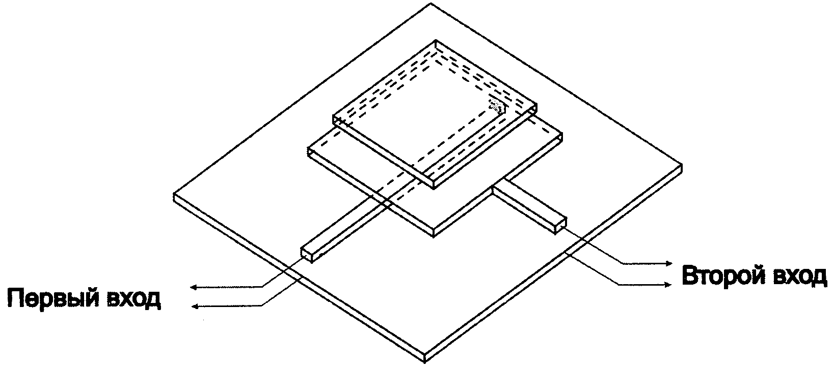
На фиг.1 показана конструкция антенны, на фиг.2 - характеристики коэффициента стоячей волны (КСВ) на входах антенны, на фиг.3 - пути протекания токов от первого и второго входов, на фиг.4 - зависимость модуля коэффициента передачи от частоты, на фиг.5 - диаграммы направленности антенны для основной и паразитной поляризации, возбуждаемой через первый вход в плоскости YOZ на частоте 2450 МГц, на фиг.6 - расчетная диаграмма направленности антенны для основной 14 и паразитной 15 поляризацией возбуждаемой через первый вход плоскости YOZ на частоте 2450 МГц.Figure 1 shows the design of the antenna, figure 2 - characteristics of the standing wave coefficient (SWR) at the inputs of the antenna, figure 3 - the path of the currents from the first and second inputs, figure 4 - the dependence of the module of the transmission coefficient from frequency, figure 5 - radiation patterns of the antenna for the main and spurious polarization excited through the first input in the YOZ plane at a frequency of 2450 MHz, figure 6 - calculated radiation pattern of the antenna for the main 14 and spurious 15 polarization excited through the first input of the plane YOZ at a frequency 2450 MHz.
На фигурах показаны: 1 - нижняя пластина (экран), 2 и 3 - средний и верхний проводники прямоугольной формы соответственно, 4 - первая полосковая или коаксиальная линия, 5 - перемычка, 6 - диэлектрические или металлические стойки, 7 - металлический проводник, 8 - вторая полосковая или коаксиальная линия, 9 - второй вход антенны, 10 - первый вход антенны, 11 - модуль коэффициента передачи, 12 и 13 диаграммы направленности антенны для основной поляризации и паразитной соответственно, 14 и 15 - расчетные диаграммы направленности антенны для основной и паразитной поляризации.The figures show: 1 - the lower plate (screen), 2 and 3 - the middle and upper conductors of a rectangular shape, respectively, 4 - the first strip or coaxial line, 5 - jumper, 6 - dielectric or metal racks, 7 - metal conductor, 8 - second stripe or coaxial line, 9 - second antenna input, 10 - first antenna input, 11 - transmission coefficient module, 12 and 13 antenna patterns for main polarization and spurious, respectively, 14 and 15 - calculated antenna patterns for main and stray olyarizatsii.
Конструкция антенны, содержащей верхнюю (3) среднюю (2) и нижнюю пластины прямоугольной или квадратной формы, разделенные диэлектриком или закрепленные на плоскости нижней пластины (1) посредством металлических или диэлектрических стоек (6). Расстояние между пластинами (2) и (1) может достигать 10% от длины волны в свободном пространстве. Размеры нижней пластины (1) могут в несколько раз превысить длину волны на рабочей частоте, но должны быть не менее габаритов пластины (2). Проводник (7) установлен примерно в середине между средней пластиной (2) и нижней (1), к одному его концу подключается 1-й приемопередатчик (к первому входу) через полосковую (8) либо коаксиальную линию передачи (либо через коаксиальный разъем), а второй конец гальванически связан через перемычку (5) с средней пластиной (2). Металлический проводник (7) находится в плоскости параллельной плоскости средней пластины (2), вблизи и параллельно ее оси симметрии. Длина проводника (7) примерно равна половине длины волны (с учетом диэлектрической проницаемости среды между средней пластиной (2) и нижней (1)) и примерно равна стороне нижнего квадратного проводника, параллельной, которой она проходит.Ширина проводника (7) подобрана из условия примерного равенства волнового сопротивления микрополосковой линии (МПЛ), об разованной проводником (7) и нижней пластиной (1), входному сопротивлению полосковой антенны в месте установки перемычки (5). 2-й приемопередатчик (второй вход) через полосковую (4) либо коаксиальную линию подключен в центр соседней стороны средней пластины (2). Антенна может быть снабжена радиопрозрачным укрытием. Расширение рабочей полосы антенны по входному импедансу на обоих входах достигнуто за счет применения дополнительной пластины (3) [1]. Согласование первого и второго входов с линиями питания идущих от приемопередатчиков достигнуто путем подбора волнового сопротивления и длины МПЛ (4) и МПЛ (8). На фигуре 2 изображены частотные зависимости КСВ на первом входе (10) и втором входе (9) антенны. Широкая полоса развязки между входами двухполяризационной МПА достигнута за счет противофазного сложения волн примерно равной амплитуды протекающих oт второго входа к точке соединения проводника (7) и МПЛ (8).The design of the antenna, containing the upper (3) middle (2) and lower plates of rectangular or square shape, separated by a dielectric or fixed on the plane of the lower plate (1) by metal or dielectric racks (6). The distance between the plates (2) and (1) can reach 10% of the wavelength in free space. The dimensions of the lower plate (1) can several times exceed the wavelength at the operating frequency, but must be no less than the dimensions of the plate (2). The conductor (7) is installed approximately in the middle between the middle plate (2) and the bottom (1), the 1st transceiver (to the first input) is connected to its end via a strip (8) or coaxial transmission line (or through a coaxial connector), and the second end is galvanically connected through a jumper (5) to the middle plate (2). The metal conductor (7) is in the plane parallel to the plane of the middle plate (2), near and parallel to its axis of symmetry. The length of the conductor (7) is approximately equal to half the wavelength (taking into account the dielectric constant of the medium between the middle plate (2) and the lower (1)) and is approximately equal to the side of the lower square conductor parallel to which it passes. The width of the conductor (7) is selected from the condition the approximate equality of the wave resistance of the microstrip line (MPL) formed by the conductor (7) and the lower plate (1), the input impedance of the strip antenna at the jumper installation site (5). The 2nd transceiver (second input) is connected through the strip (4) or coaxial line to the center of the adjacent side of the middle plate (2). The antenna can be equipped with a radiotransparent shelter. The extension of the antenna working band at the input impedance at both inputs is achieved through the use of an additional plate (3) [1]. The coordination of the first and second inputs with the power lines coming from the transceivers was achieved by selecting the wave impedance and the length of the MPL (4) and MPL (8). The figure 2 shows the frequency dependence of the SWR at the first input (10) and second input (9) of the antenna. A wide decoupling band between the inputs of the bipolarization MPA was achieved due to the out-of-phase addition of waves of approximately equal amplitude from the second input to the junction of conductor (7) and MPL (8).
Работа антенны происходит следующим образом. При возбуждении второго входа ток I1 имеющий 0Х-составляющую (Фиг.3) протекает в точку соединения проводника (7) и МПЛ (8) через короткозамкнутый перемычкой (5) отрезок несимметричной линии передачи образованной проводником (7) и пластины (2), а ток I2 протекает от МПЛ (4) через перемычку (5) и микрополосковую линию, образованную проводником (7) и экраном (1) к этой же точке. Вследствие симметрии пластины (2) относительно оси 0Y амплитуды токов примерно равны. Очевидно, что токи приходят в точку соединения проводника (7) и МПЛ (8) с разностью фаз - 180 градусов при длине проводника (7) равной половины длины волны на центральной частоте антенны. При отстройке частоты от центральной в пределах 7-10% разница фаз токов сохраняется и наблюдается не значительное увеличение модуля коэффициента передачи (11) между первым и вторым входами (Фиг.4). Расчетные диаграммы направленности антенны для основной (12) и паразитной (13) поляризации возбуждаемой через первый вход i плоскости YOZ на частоте 2450МГц показаны на фигуре 5. Расчетные диаграм мы направленности антенны для основной(Н) и паразитной(15) поляризаци] возбуждаемой через первый вход в плоскости XOZ на частоте 2450МГц показа ны на фигуре 6. Аналогичные диаграммы направленности имеет антенна npi возбуждении второго входа.The operation of the antenna is as follows. When the second input is excited, a current I 1 having a 0X component (Figure 3) flows to the junction point of the conductor (7) and the MPL (8) through a segment of the asymmetric transmission line formed by the conductor (7) and plate (2), shorted by a jumper (5), and the current I 2 flows from the MPL (4) through the jumper (5) and the microstrip line formed by the conductor (7) and the shield (1) to the same point. Due to the symmetry of the plate (2) with respect to the 0Y axis, the current amplitudes are approximately equal. Obviously, the currents arrive at the junction of the conductor (7) and the MPL (8) with a phase difference of 180 degrees with the length of the conductor (7) equal to half the wavelength at the center frequency of the antenna. When the frequency detuning from the central one within 7-10%, the phase difference of the currents is preserved and there is a slight increase in the transmission coefficient module (11) between the first and second inputs (Figure 4). The calculated antenna patterns for the main (12) and spurious (13) polarization of the YOZ plane excited through the first input i at a frequency of 2450 MHz are shown in Figure 5. The calculated antenna patterns for the main (H) and spurious (15) polarization] excited through the first an input in the XOZ plane at a frequency of 2450 MHz is shown in Fig. 6. A similar radiation pattern has the npi antenna excited by the second input.
При возбуждении первого входа антенна излучает поле линейной поляри зации ортогональной по отношению к поляризации поля, возбуждаемой по вто рому входу. Принцип работы по этому (первому) входу идентичен втором:When the first input is excited, the antenna emits a linear polarization field orthogonal to the polarization of the field excited by the second input. The principle of operation on this (first) input is identical to the second:
входу, различие только в поляризации полей, а наличие проводника 7 и ег подключение способствует увеличению' развязки между входами антенны широкой полосе частот.to the input, the difference is only in the polarization of the fields, and the presence of a conductor 7 and its connection helps to increase the isolation between the inputs of the antenna over a wide frequency band.
Claims (1)
Priority Applications (1)
| Application Number | Priority Date | Filing Date | Title |
|---|---|---|---|
| RU2010150976/07U RU118474U1 (en) | 2010-12-13 | 2010-12-13 | BROADBAND STRIP ANTENNA WITH DOUBLE POLARIZATION |
Applications Claiming Priority (1)
| Application Number | Priority Date | Filing Date | Title |
|---|---|---|---|
| RU2010150976/07U RU118474U1 (en) | 2010-12-13 | 2010-12-13 | BROADBAND STRIP ANTENNA WITH DOUBLE POLARIZATION |
Publications (1)
| Publication Number | Publication Date |
|---|---|
| RU118474U1 true RU118474U1 (en) | 2012-07-20 |
Family
ID=46847938
Family Applications (1)
| Application Number | Title | Priority Date | Filing Date |
|---|---|---|---|
| RU2010150976/07U RU118474U1 (en) | 2010-12-13 | 2010-12-13 | BROADBAND STRIP ANTENNA WITH DOUBLE POLARIZATION |
Country Status (1)
| Country | Link |
|---|---|
| RU (1) | RU118474U1 (en) |
Cited By (4)
| Publication number | Priority date | Publication date | Assignee | Title |
|---|---|---|---|---|
| RU2530242C1 (en) * | 2013-04-09 | 2014-10-10 | Открытое акционерное общество "Научно-производственное объединение измерительной техники" | Antenna |
| RU172145U1 (en) * | 2016-12-30 | 2017-06-29 | Общество С Ограниченной Ответственностью "Научно-Производственное Предприятие Антэкс" | BROADBAND DIRECTED ANTENNA WITH TWO ORTHOGONAL POLARIZATIONS |
| RU2673059C2 (en) * | 2014-01-15 | 2018-11-22 | Ханивелл Интернешнл Инк. | Antenna array feeding structure having circuit boards connected by at least one solderable pin |
| RU2691121C1 (en) * | 2018-06-09 | 2019-06-11 | Акционерное общество "Научно-производственное объединение Измерительной техники" (АО "НПО ИТ") | Double-polarization antenna |
-
2010
- 2010-12-13 RU RU2010150976/07U patent/RU118474U1/en not_active IP Right Cessation
Cited By (4)
| Publication number | Priority date | Publication date | Assignee | Title |
|---|---|---|---|---|
| RU2530242C1 (en) * | 2013-04-09 | 2014-10-10 | Открытое акционерное общество "Научно-производственное объединение измерительной техники" | Antenna |
| RU2673059C2 (en) * | 2014-01-15 | 2018-11-22 | Ханивелл Интернешнл Инк. | Antenna array feeding structure having circuit boards connected by at least one solderable pin |
| RU172145U1 (en) * | 2016-12-30 | 2017-06-29 | Общество С Ограниченной Ответственностью "Научно-Производственное Предприятие Антэкс" | BROADBAND DIRECTED ANTENNA WITH TWO ORTHOGONAL POLARIZATIONS |
| RU2691121C1 (en) * | 2018-06-09 | 2019-06-11 | Акционерное общество "Научно-производственное объединение Измерительной техники" (АО "НПО ИТ") | Double-polarization antenna |
Similar Documents
| Publication | Publication Date | Title |
|---|---|---|
| Li et al. | Isolation-improved dual-band MIMO antenna array for LTE/WiMAX mobile terminals | |
| Zhu et al. | A simple approach for reducing mutual coupling in two closely spaced metamaterial-inspired monopole antennas | |
| Abdullah et al. | Eight-element antenna array at 3.5 GHz for MIMO wireless application | |
| EP1944828A2 (en) | Planar antenna | |
| ES2817930T3 (en) | Slot antenna | |
| US20130002510A1 (en) | Antennas with novel current distribution and radiation patterns, for enhanced antenna islation | |
| US20170085009A1 (en) | Low-profile, broad-bandwidth, dual-polarization dipole radiating element | |
| JP6318392B2 (en) | 2-port triplate line-waveguide converter | |
| JP2012019281A (en) | Antenna device, and wireless device | |
| US20100328173A1 (en) | Single feed planar dual-polarization multi-loop element antenna | |
| CN107809008B (en) | In-band full duplex antenna based on 180-degree hybrid loop | |
| Parmar et al. | Review of Microstrip patch antenna for WLAN and Wimax application | |
| WO2011030703A1 (en) | Inverse-l shaped antenna | |
| RU118474U1 (en) | BROADBAND STRIP ANTENNA WITH DOUBLE POLARIZATION | |
| Kumar et al. | High-isolated WiFi-2.4 GHz/LTE MIMO antenna for RF-energy harvesting applications | |
| JP2012129943A (en) | Antenna device | |
| Hussain et al. | A dielectric resonator based millimeter-wave MIMO antenna array for hand-held devices | |
| JP3725415B2 (en) | Diversity antenna device | |
| CN109546330A (en) | A kind of feedback antenna of double frequency three of integrated combiner | |
| CN109378580B (en) | Dual-frequency circularly polarized monopole antenna with wide axial ratio bandwidth | |
| Yussuf et al. | Design of wideband MIMO antenna for wireless applications | |
| CN108063312B (en) | Mobile terminal broadband MIMO dual-antenna | |
| Bonthu et al. | An investigation of multiband triangular microstrip patch antenna using DGS | |
| RU2557478C2 (en) | Broadband two-polarisation antenna | |
| CN110247175A (en) | A kind of filtering duplexed antenna based on hair fastener type resonator |
Legal Events
| Date | Code | Title | Description |
|---|---|---|---|
| MM1K | Utility model has become invalid (non-payment of fees) |
Effective date: 20120720 |
|
| NF1K | Reinstatement of utility model |
Effective date: 20140610 |
|
| MM1K | Utility model has become invalid (non-payment of fees) |
Effective date: 20161214 |