RU115840U1 - GEAR PUMP WITH REDUCED PRESSURE REDUCTION - Google Patents
GEAR PUMP WITH REDUCED PRESSURE REDUCTION Download PDFInfo
- Publication number
- RU115840U1 RU115840U1 RU2011146619/06U RU2011146619U RU115840U1 RU 115840 U1 RU115840 U1 RU 115840U1 RU 2011146619/06 U RU2011146619/06 U RU 2011146619/06U RU 2011146619 U RU2011146619 U RU 2011146619U RU 115840 U1 RU115840 U1 RU 115840U1
- Authority
- RU
- Russia
- Prior art keywords
- housing
- chamber
- gears
- reduced pressure
- gear pump
- Prior art date
Links
Abstract
Шестеренный насос с пониженной пульсацией давления, содержащий корпус, крышку, ведущую и ведомую шестерни, корпус имеет камеру, соединенную с нагнетательной полостью, в камере установлен плунжер, поджатый пружиной с возможностью поступательного движения внутри камеры, отличающийся тем, что корпус включает в себя две ведущих и две ведомых шестерни, причем ведущие шестерни спарены между собой и зубья одной из них смещены относительно другой на половину шага между зубьями. A gear pump with reduced pressure pulsation, containing a housing, a cover, a driving and a driven gear, the housing has a chamber connected to the discharge cavity, a plunger is installed in the chamber, compressed by a spring with the possibility of translational movement inside the chamber, characterized in that the housing includes two leading and two driven gears, wherein the driving gears are paired with each other and the teeth of one of them are offset relative to the other by half the pitch between the teeth.
Description
Полезная модель относится к машиностроению, в частности к объемным гидравлическим машинам и может использоваться в гидрофицированных машинах.The utility model relates to mechanical engineering, in particular to volumetric hydraulic machines and can be used in hydraulic machines.
Известен шестеренный насос с пассивным гасителем колебаний (Патент №104257, МПК F04C 2/18), содержащий корпус, крышку, ведущую и ведомую шестерни, корпус имеет камеру, соединенную с нагнетательной полостью, в камере установлен плунжер, поджатый пружиной с возможностью поступательного движения внутри камеры.A known gear pump with a passive vibration damper (Patent No. 104257, IPC F04C 2/18), comprising a housing, a cover, a drive and a driven gear, the housing has a chamber connected to the discharge cavity, a plunger installed in the chamber, preloaded by a spring with the possibility of translational movement inside cameras.
К недостаткам данной полезной модели относится неравномерность подачи рабочей жидкости, изменяющейся по эпициклоидальной зависимости.The disadvantages of this utility model include the uneven supply of the working fluid, which varies according to the epicycloidal dependence.
Задача, на решение которой направлена полезная модель - снижение пульсаций подачи рабочей жидкости.The problem the utility model aims to solve is to reduce fluctuations in the supply of working fluid.
Техническим результатом, который достигается за счет использования предлагаемой полезной модели, является повышение надежности гидросистем, уменьшение вероятности возникновения резонансных колебаний в напорной магистрали гидросистем.The technical result, which is achieved through the use of the proposed utility model, is to increase the reliability of hydraulic systems, reducing the likelihood of resonance oscillations in the pressure line of hydraulic systems.
Указанный технический результат достигается тем, что шестеренный насос с пониженной пульсацией давления, содержащий, корпус, крышку, ведущую и ведомую шестерни, корпус имеет камеру, соединенную с нагнетательной полостью, в камере установлен плунжер, поджатый пружиной с возможностью поступательного движения внутри камеры, кроме того, корпус включает в себя две ведущих и две ведомых шестерни, причем ведущие шестерни спарены между собой и зубья одной из них смещены относительно другой на половину шага между зубьями.The specified technical result is achieved in that the gear pump with reduced pressure pulsation, comprising, a housing, a cover, a drive and a driven gear, the housing has a chamber connected to the discharge cavity, a plunger is installed in the chamber, preloaded by a spring with the possibility of translational movement inside the chamber, in addition , the housing includes two driving and two driven gears, and the driving gears are paired with each other and the teeth of one of them are offset relative to the other by half a step between the teeth.
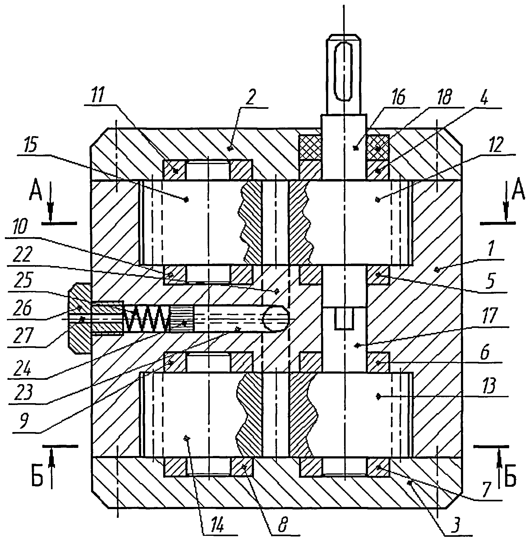
На фиг.1 изображен шестеренный насос с пониженной пульсацией давления. На фиг.2 - вид А-А первой ступени шестеренного насоса и вид Б-Б второй ступени. На фиг.3 представлен график пульсаций давления соответственно: а) пульсация давления от первой ступени насоса; б) пульсация давления от второй ступени насоса; в) суммарная пульсация давления от обеих ступеней.Figure 1 shows a gear pump with reduced pressure pulsation. Figure 2 - view aa the first stage of the gear pump and view bb of the second stage. Figure 3 presents a graph of pressure pulsations, respectively: a) pressure pulsation from the first stage of the pump; b) pressure pulsation from the second stage of the pump; c) the total pressure pulsation from both stages.
Устройство состоит из корпуса 1, передней крышки 2, задней крышки 3, в корпусе 1 на втулках 4-7 и 8-11 соответственно установлены ведущие 12, 13 и ведомые 14, 15 шестерни, охватываемые со всех сторон стенками корпуса 1 с малыми зазорами. Ведущая шестерня 12 выполнена как единое целое с валом 16, а ведущая шестерня 13 - с валом 17, причем вал 16 жестко соединен с валом 17 таким образом, что ведущие шестерни 12, 13 спарены между собой и зубья одной из них смещены относительно другой на половину шага между зубьями. Для предотвращения утечек жидкости между корпусом 1 и валом 16 установлено герметизирующее уплотнение 18. В корпусе 1 (фиг.2, вид А-А) выполнены всасывающее 19 и нагнетательное 20 отверстия, соответственно связанные с всасывающей 21 и нагнетательной 22 полостями. В корпусе 1 выполнена цилиндрическая камера 23, соединенная непосредственно с нагнетательной полостью 22. В камере 23 установлен плунжер 24, пружина 25 удерживается заглушкой 26, в которой выполнено дроссельное отверстие 27 для перепуска воздуха.The device consists of a housing 1, a front cover 2, a rear cover 3, in the housing 1 on the bushings 4-7 and 8-11, respectively, driving gears 12, 13 and driven gears 14, 15 are mounted, covered on all sides by the walls of the housing 1 with small gaps. The pinion gear 12 is made integrally with the shaft 16, and the pinion gear 13 with the shaft 17, and the shaft 16 is rigidly connected to the shaft 17 so that the pinion gears 12, 13 are paired with one another and the teeth of one of them are half offset pitch between the teeth. To prevent fluid leakage between the housing 1 and the shaft 16, a sealing seal 18 is installed. In the housing 1 (FIG. 2, view A-A), there are suction holes 19 and 20 for discharge, respectively connected to the suction 21 and 22 discharge cavities. A cylindrical chamber 23 is made in the housing 1 and is connected directly to the injection cavity 22. A plunger 24 is installed in the chamber 23, the spring 25 is held by a plug 26, in which a throttle hole 27 is made for air bypass.
Устройство работает следующим образом.The device operates as follows.
При вращении шестерен 12 и 13 по часовой стрелке, шестерни 14 и 15 вращаются против часовой стрелки. Жидкость из всасывающей полости 13 захватывается зубьями и переносится в межзубовом пространстве шестерен в нагнетательную полость 22, откуда жидкость под давлением попадает в камеру 23. Неравномерность эвольвентного зацепления шестерен вызывает пульсации подачи жидкости и пульсации давления в нагнетательной полости 22 и соответственно соединенной с ней камере 23. При всплеске подачи рабочей жидкости и давления в камере 23, плунжер 24, сжимая пружину 25, перемещается вниз (фиг.1), увеличивая объем нагнетательной полости 22 на величину, равную амплитуде пульсации подачи рабочей жидкости. Перемещаясь вниз, плунжер 24 вытесняет воздух из подплунжерного пространства через дроссельное отверстие 27 в заглушке 26, тем самым происходит частичное демпфирование. При спаде пульсации подачи рабочей жидкости плунжер 16 под действием восстанавливающей силы пружины 25 возвращается в исходное положение. При периодических колебаниях подачи рабочей жидкости, изменяющихся по эпициклоидальному закону, плунжер 24 также совершает колебания, тем самым рабочий объем нагнетательной полости постоянно изменяется на величину пульсации, что в результате дает на выходе из нагнетательного отверстия 20 постоянную подачу рабочей жидости.When the gears 12 and 13 rotate clockwise, the gears 14 and 15 rotate counterclockwise. The fluid from the suction cavity 13 is captured by the teeth and transferred into the interdental space of the gears into the injection cavity 22, from where the fluid under pressure enters the chamber 23. The uneven involute engagement of the gears causes pulsations in the fluid supply and pressure pulsations in the injection cavity 22 and, accordingly, the chamber 23 connected to it. When a surge in the supply of working fluid and pressure in the chamber 23, the plunger 24, compressing the spring 25, moves down (figure 1), increasing the volume of the injection cavity 22 by an amount equal to am litude pulsations supplying the working fluid. Moving downward, the plunger 24 displaces air from the subplunger space through the throttle hole 27 in the plug 26, thereby partially damping. When the pulsation of the supply of the working fluid decreases, the plunger 16 under the action of the restoring force of the spring 25 returns to its original position. With periodic fluctuations in the flow of the working fluid, changing according to the epicycloidal law, the plunger 24 also oscillates, thereby the working volume of the injection cavity is constantly changing by the amount of pulsation, which results in a constant supply of working fluid at the outlet from the injection opening 20.
При вращении шестерен первой ступени (фиг.2, вид А-А) пульсация подачи рабочей жидкости изменяется по закону (фиг.3а), вторая ступень - шестерни 13, 14 осуществляет подачу рабочей жидкости в напорную полость 22 по зависимости (фиг.3б). Так как обе ступени осуществляют подачу в одну полость 22, то закон изменения давления в нагнетательной полости 22 будет выглядеть в виде диаграммы (фиг.3в).When the gears of the first stage rotate (Fig. 2, view A-A), the pulsation of the working fluid supply changes according to the law (Fig. 3a), the second stage - gears 13, 14 feed the working fluid into the pressure cavity 22 according to (Fig. 3b) . Since both stages feed into one cavity 22, the law of pressure change in the injection cavity 22 will look like a diagram (Fig. 3c).
Таким образом, полезная модель предназначена для снижения пульсаций подачи рабочей жидкости и снижения вибраций в гидросистеме и повышения ее надежности.Thus, the utility model is designed to reduce fluctuations in the flow of the working fluid and reduce vibrations in the hydraulic system and increase its reliability.
Claims (1)
Priority Applications (1)
| Application Number | Priority Date | Filing Date | Title |
|---|---|---|---|
| RU2011146619/06U RU115840U1 (en) | 2011-11-16 | 2011-11-16 | GEAR PUMP WITH REDUCED PRESSURE REDUCTION |
Applications Claiming Priority (1)
| Application Number | Priority Date | Filing Date | Title |
|---|---|---|---|
| RU2011146619/06U RU115840U1 (en) | 2011-11-16 | 2011-11-16 | GEAR PUMP WITH REDUCED PRESSURE REDUCTION |
Publications (1)
| Publication Number | Publication Date |
|---|---|
| RU115840U1 true RU115840U1 (en) | 2012-05-10 |
Family
ID=46312688
Family Applications (1)
| Application Number | Title | Priority Date | Filing Date |
|---|---|---|---|
| RU2011146619/06U RU115840U1 (en) | 2011-11-16 | 2011-11-16 | GEAR PUMP WITH REDUCED PRESSURE REDUCTION |
Country Status (1)
| Country | Link |
|---|---|
| RU (1) | RU115840U1 (en) |
Cited By (2)
| Publication number | Priority date | Publication date | Assignee | Title |
|---|---|---|---|---|
| CN104564660A (en) * | 2015-01-16 | 2015-04-29 | 上海大学 | Low-pulse compound gear pump |
| RU2553848C1 (en) * | 2014-05-28 | 2015-06-20 | Виктор Владимирович Становской | Gear machine |
-
2011
- 2011-11-16 RU RU2011146619/06U patent/RU115840U1/en not_active IP Right Cessation
Cited By (3)
| Publication number | Priority date | Publication date | Assignee | Title |
|---|---|---|---|---|
| RU2553848C1 (en) * | 2014-05-28 | 2015-06-20 | Виктор Владимирович Становской | Gear machine |
| WO2015183135A1 (en) * | 2014-05-28 | 2015-12-03 | Закрытое Акционерное Общество "Технология Маркет" | Gear machine |
| CN104564660A (en) * | 2015-01-16 | 2015-04-29 | 上海大学 | Low-pulse compound gear pump |
Similar Documents
| Publication | Publication Date | Title |
|---|---|---|
| CN105736657A (en) | Chain tensioner | |
| JP2017198103A (en) | Complex function device | |
| EA200701999A3 (en) | METHOD OF WORK OF THE SPHERICAL BULK OF ROTARY MACHINE AND DEVICE ITS REALIZING | |
| WO2014171744A8 (en) | A silent gear pump or motor suppressing troubles of trapping fluid | |
| RU115840U1 (en) | GEAR PUMP WITH REDUCED PRESSURE REDUCTION | |
| US2811931A (en) | Timed surge neutralizer | |
| US20080019846A1 (en) | Variable displacement gerotor pump | |
| CN209115997U (en) | It is a kind of to can solve high speed flow rotor-type oil pump more than needed | |
| RU104257U1 (en) | GEAR PUMP WITH PASSIVE OSCILLATOR | |
| RU2560649C1 (en) | Piston compression pump | |
| JP4412284B2 (en) | Pressure regulating valve | |
| WO2016182490A1 (en) | A reversible pump and a method to control a reversible pump | |
| RU178984U1 (en) | Compressor installation | |
| CN205877675U (en) | Gear type oil pump | |
| RU185364U1 (en) | GEAR PUMP | |
| CN203321613U (en) | Rotor type oil pump of internal combustion engine | |
| RU2369776C2 (en) | Rotary compressor | |
| CN209744020U (en) | novel oil pump structure based on generator | |
| CN112696349B (en) | Plunger pump structure | |
| RU199143U1 (en) | Gerotor pump | |
| CN212690245U (en) | Combined cylindrical cam piston pump | |
| RU187490U1 (en) | OIL PUMP | |
| IT201800009496A1 (en) | PUMPING GROUP TO FEED FUEL, PREFERABLY DIESEL, TO AN INTERNAL COMBUSTION ENGINE | |
| CN202419100U (en) | 1.2 L and under engine oil pump | |
| CN101975161A (en) | Gear pump |
Legal Events
| Date | Code | Title | Description |
|---|---|---|---|
| MM1K | Utility model has become invalid (non-payment of fees) |
Effective date: 20120511 |