KR960006359B1 - Pilot check valve having low-velocity-return function - Google Patents
Pilot check valve having low-velocity-return function Download PDFInfo
- Publication number
- KR960006359B1 KR960006359B1 KR1019890007641A KR890007641A KR960006359B1 KR 960006359 B1 KR960006359 B1 KR 960006359B1 KR 1019890007641 A KR1019890007641 A KR 1019890007641A KR 890007641 A KR890007641 A KR 890007641A KR 960006359 B1 KR960006359 B1 KR 960006359B1
- Authority
- KR
- South Korea
- Prior art keywords
- valve
- pilot
- check valve
- chamber
- hydraulic
- Prior art date
Links
Images

Classifications
-
- F—MECHANICAL ENGINEERING; LIGHTING; HEATING; WEAPONS; BLASTING
- F15—FLUID-PRESSURE ACTUATORS; HYDRAULICS OR PNEUMATICS IN GENERAL
- F15B—SYSTEMS ACTING BY MEANS OF FLUIDS IN GENERAL; FLUID-PRESSURE ACTUATORS, e.g. SERVOMOTORS; DETAILS OF FLUID-PRESSURE SYSTEMS, NOT OTHERWISE PROVIDED FOR
- F15B11/00—Servomotor systems without provision for follow-up action; Circuits therefor
- F15B11/02—Systems essentially incorporating special features for controlling the speed or actuating force of an output member
-
- F—MECHANICAL ENGINEERING; LIGHTING; HEATING; WEAPONS; BLASTING
- F16—ENGINEERING ELEMENTS AND UNITS; GENERAL MEASURES FOR PRODUCING AND MAINTAINING EFFECTIVE FUNCTIONING OF MACHINES OR INSTALLATIONS; THERMAL INSULATION IN GENERAL
- F16K—VALVES; TAPS; COCKS; ACTUATING-FLOATS; DEVICES FOR VENTING OR AERATING
- F16K17/00—Safety valves; Equalising valves, e.g. pressure relief valves
- F16K17/02—Safety valves; Equalising valves, e.g. pressure relief valves opening on surplus pressure on one side; closing on insufficient pressure on one side
- F16K17/04—Safety valves; Equalising valves, e.g. pressure relief valves opening on surplus pressure on one side; closing on insufficient pressure on one side spring-loaded
Abstract
내용 없음.No content.
Description
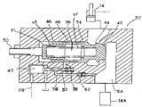
제 l 도는 이 발명에 의한 저속복기기능을 부가한 파일럿첵밸브의 한 실시예를 표시하는 단면도.1 is a cross-sectional view showing an embodiment of a pilot valve with a low speed regeneration function according to the present invention.
제 2 도는 종래의 저속복귀 밸브기구를 응용한 유압회로의 실시예을 표시하는 계통도이다.2 is a system diagram showing an embodiment of a hydraulic circuit to which a conventional low speed return valve mechanism is applied.
* 도면의 주요부분에 대한 부호의 설명* Explanation of symbols for main parts of the drawings
14,22 : 실린더 14a,22a : 제어 밸브14,22:
26 : 신호선 30 : 저속복귀파일럿밸브26: signal line 30: low speed return pilot valve
32 : 파일럿포핏밸브 34 : 주첵밸브32: pilot poppet valve 34: main valve
35 : 스프링 36 : 유압실35: spring 36: hydraulic chamber
38,44,49 : 유로 40 : 피스톤38,44,49: Euro 40: Piston
42 : 돌기부 46 : 유압인출구멍42: projection 46: hydraulic drawing hole
48 : 원통부재 50 : 조정나사48: cylindrical member 50: adjusting screw
51 : 배실 52 : 첵밸브51: exhaust chamber 52: check valve
54 : 제어밸브실린더포트축실 56 : 통로54: control valve cylinder port shaft chamber 56: passage
이 발명은 건설기계(특히 유압셔블)에 있어서, 유압액츄에이터로 구동되는 붐(boom) 등의 자연강하를 방지하는 저속복귀밸브(slow return valve) 기구에 관한 것이다.BACKGROUND OF THE INVENTION 1. Field of the Invention The present invention relates to a slow return valve mechanism for preventing a natural drop of a boom or the like driven by a hydraulic actuator in a construction machine (particularly a hydraulic excavator).
일반적으로 유압셔블(shovel)에 있어서는 작업의 안정성 및 차체의 안정성의 면에서 붐이나 암의 자연강하를 방지할 필요가 있으며, 이 때문에 상기 붐이나 암용 액츄에이터(actuator)에는 그 복귀유량을 규재하기 위한 저속복귀밸브기구가 설치되어 있다.In general, in the shovel, it is necessary to prevent the natural drop of the boom or the arm in terms of the stability of the work and the stability of the vehicle body. Therefore, the boom or the arm actuator is used to regulate the return flow rate. Low speed return valve mechanism is installed.
그리고 이 저속복귀밸브기구는 액츄에이터를 구동하는 제어밸브의 스풀(spoo1)내에 설치하는 스토틀(throttle)로 구성하든가 혹은 액츄에이터와 상기 스로틀 사이에 설치하는 저속복귀밸브 및 파일럿첵밸브로 구성하고 있다.The low speed return valve mechanism is composed of a throttle installed in a spool (spoo1) of a control valve for driving an actuator, or a low speed return valve and a pilot valve provided between the actuator and the throttle.
그런데 전자의 구성으로된 밸브기구에 있어서는, 밸브본체와 스풀간에 스라이딩하는 틈새가 개재하므로 최저한의 누설을 피할 수 없으며, 액츄에이터로부터 복귀유의 차단을 확실하게 달성할 수 없다는 결함이 발생한다.However, in the valve mechanism of the former configuration, since a gap for sliding between the valve body and the spool is interposed, a minimum leakage is inevitable and a defect occurs that the shutoff of the return oil from the actuator cannot be reliably achieved.
이 때문에 특히 유압회로의 압력이 고압화됨에 따라 액츄에이터로부터의 복귀유가 확실하게 달성되는 후자의 구성으로 되는 밸브기구(이하 첵밸브방식이라 함)를 선호하기에 이르렀다. 그런데 상기 첵밸브방식은 상술한 바와같이 저속복귀첵밸브와 파일럿밸브의 2종의 첵밸브로 복합구성되기 때문에 구조가 복잡하게 되는 기본적인 난점이 있다.For this reason, in particular, as the pressure of the hydraulic circuit is increased, the valve mechanism (hereinafter, referred to as the `` valve valve method) having the latter configuration in which the return oil from the actuator is reliably achieved has been preferred. However, since the check valve method is composed of two types of check valves, a low speed return check valve and a pilot valve as described above, there is a basic difficulty in that the structure becomes complicated.
즉, 상기 양 첵밸브를 밸브체내에 설치하는 경우에는 저속복귀밸브기구를 필요로 하지 않는 제어밸브부분을 포함시켜 복합제어밸브 전체가 극히 대형화된다.That is, when the two check valves are provided in the valve body, the entire control valve is extremely large, including the control valve portion that does not require the low speed return valve mechanism.
한편, 양 첵밸브를 밸브체외에 설치하는 경우에는 양 첵밸브 외에 액츄에이터용 릴리프밸브 및 새로운 탱크통로로도 밸브체외에 설치할 필요가 있으며 제조비용이 대폭 상승한다.On the other hand, in the case where both check valves are installed outside the valve body, the actuator relief valves and the new tank passages need to be installed outside the valve body in addition to the two check valves, and the manufacturing cost greatly increases.
이 때문에 본 출원인은 상술한 같은 난점을 해결하기 위하여 저속복귀밸브기구만을 필요한 개소에만 밸브체외에 간단히 설치할 수 있는 유압회로를 개발하여 특허 출원하였다(일본 특원소 63-123338호)For this reason, the present applicant has developed and applied for a patent for a hydraulic circuit that can be easily installed outside the valve only in a location where only a low speed return valve mechanism is required to solve the above-mentioned difficulties (Japanese Patent Application No. 63-123338).
이하, 상기 특허출원에 관한 유압회로에 대하여 간단히 설명한다.Hereinafter, the hydraulic circuit according to the above patent application will be briefly described.
상기 특허출원 유압회로는 제2도와 같이 2개의 펌프(10a)(l0b)로부터의 토출유가 공급되는 2개의 복합제어밸브(12a)(12b)내의 각 제어밸브(l4a)(16a)(18a)(20a)(22a)(24a)에 의하여 각각 암용실린더(14), 선회용모터(16), 좌주행용모터(18), 우주행용모터(20), 붐용실린더(22), 버킷용실린더(24)가 구동하는 유압회로에 있어서, 암용실린더(14)와 그 제어밸브(l4a) 사이 및 부용실린더(22)와 그 제어밸브(22a) 사이에 각각 파일럿첵밸브(l4b)(22b) 및 저속복귀첵밸브(14c)(22c)를 설치하고, 각 제어밸브(14a)(22a)(24a)에 각각 절환밸브(14d)(22d)(24d)를 설치하며, 상기 저속복귀첵밸브(14c)(22c)에 신호선(26)을 통하여 파일럿펌프의 밸브개폐 신호를 공급하도록 구성되어 있다.The patent application hydraulic circuit has control valves l4a, 16a and 18a in two
그리고 이와같은 구성에 있어서, 각 제어밸브(14a)(22a)(24a)가 중립상태이면은 각 파일럿첵밸브(14b)(22b)는 절활밸브(14d)(22d)(24d)를 통하여 폐로되므로 암용실린더(14), 붐용실린더(22), 버킷용실린더(24)로부터의 복귀가 확실하게 차단된다.In such a configuration, when each of the
한편, 각 파일럿첵밸브(14b)(22b)는 각 제어밸브(14a)(22a)(24a)가 조작되면은 소정의 타이밍으로 개방되므로 액츄에이터의 급정지 등에 의하여 유압회로내의 이상고압이 발생한 경우에 과부하릴리프밸브(14e)(22e)(24e)의 작동을 방해하는 일이 없다.On the other hand, each
이와같이 선출원의 유압회로에 의하여 소요의 액츄에이터로부터의 복귀유를 확실하게 차단할 수가 있는 저속복귀밸브기구를 필요한 개소에만 밸브체외에 간편하에 설치할 수가 있다. 그렇지만은, 상술의 선출원의 유압회로는 필요한 개소에만 설치할 수도 있으나 저속복귀밸브기구가 별도의 양첵벨브로 구성된 점에 있어서, 더욱 개선될 여지가 있었다.In this way, the low-speed return valve mechanism capable of reliably blocking the return oil from the required actuator by the hydraulic circuit of the prior application can be easily installed outside the valve body only where necessary. However, although the hydraulic circuit of the above-mentioned prior application may be provided only where necessary, there is room for further improvement in that the low speed return valve mechanism is constituted by a separate double check valve.
그래서 이 발명의 목적은 유압셔블 등의 부하를 보존하는 액츄에이터로부터의 복귀유량을 규제하는 밸브체외에 설치하는 복합첵밸브형 저속복귀밸브기구에 있어서, 한쪽의 저속복귀첵밸브를 다른쪽의 파일럿첵밸브내에 조립하는 구성으로 함으로써, 상기 저속복귀밸브기구를 더욱 간단하고, 또한 염가로 제조할 수 있는 저속복귀기능을 부가한 파일럿첵밸브를 제공하는데 있다.Therefore, an object of the present invention is to provide a composite valve type low speed return valve mechanism provided outside the valve body that regulates the return flow rate from an actuator that preserves a load such as a hydraulic excavator. By providing an assembly in the valve, it is possible to provide a pilot check valve with a low speed return function that enables the low speed return valve mechanism to be manufactured more simply and inexpensively.
상기 목적을 달성하기 위하여, 이 발명에 의한 저속복귀기구를 부가한 파일럿첵밸브는 해제신호(26)에 의하여 작동하는 파일럿밸브(32)와 이 파일럿밸브의 작동에 의하여 첵밸브기능이 해제되는 주첵밸브(34)를 갖춘 파일럿첵밸브(30)로 구성되고, 상기 주첵밸브(34)는 이것을 밸브시트에 대하여 탄력적으로 가압 착좌시키는 스프링(35)부 유압실(36)을 가지는 동시에, 상기 유압실(36)내에 있어서 상기 스프링(35)의 일단을 보존하여 되고, 한편 상기 스프링(35)의 타단을 보존하여 상기 주첵크밸브(34)에 대한 배실을 구획하는 축방향으로 조정 가능한 원통부재(48)를 설치하여, 이들 배실(51)과 유압실(36)를 첵밸브의 2차측에 대하여 각각 유로(49)(44)에 의해 연통하도륵 구성하며, 상기 파일럿밸브(32)는 상기 주첵밸브(34)의 소정의 스트로크량에 의행 개폐되는 통로(46)(38)를 통하여, 상기 유압실에 연통하는 동시에 그 내부압력을 저압으로 되는 첵밸브의 1차측으로 개방하는 바이패스통로(56)을 가지고, 상기 주첵밸브(34)의 1차측이 고압으로 될 때에는, 상기 배실(51) 및 유압실(36)내의 압유를 첵밸브의 2차측으로 흘려, 상기 첵밸브의 후단이 상기 스프링(35)의 탄력에 대항하여 상기 배실(51)이 끝면에 접촉 할 때까지의 최대 스트로크를 이동할 수 있도록 설정하여 1차측 압유의 2차측으로서의 자유 흐름을 달성하며, 제어밸브(14a)의 전환에 의해 상기 주첵벨브(34)의 2차측이 고압으로 되는 압유의 복귀유가 흐를 때에는 상기 해제신호(26)에 의해 파일럿밸브(32)를 개방하여, 상기 유압실(36)내의 압유를 첵밸브의 1차측으로 흘리고, 첵밸브를 리프트하여 이것을 상기 통로(46)(38)이 폐쇄되는 설정 위치에서 정시시켜 첵밸브의 돌기부(42)의 개도를 규제함으로써 상기 복귀량을 규제하도록 구성한 것을 특징으로 한다.In order to achieve the above object, the pilot check valve to which the low-speed return mechanism according to the present invention is added has a
이 경우, 주첵크밸브(34)의 소정의 스트로크량에 의해 통로(46)(38)을 개폐하는 수단으로서, 상기 스트로크량을 조절하는 수단(50)을 설치할 수 있다.In this case, the
이 발명의 저속복귀기능를 부가한 파일럿첵밸브에 의하면, 주첵밸브의 1차측이 고압이며, 2차측이 저압의 경우 2차측과 배실 및 유압실과는 같은 압력으로 되고 서로 연통하고 있으므로, 상기 첵밸브의 후단은 스프링의 탄력에 대항하여 상기 배실의 끝면에 접촉할 때까지의 최대 스트로크를 이동할 수 있도록 설정되어 압유의 1차측으로부터 2차측으로의 자유 흐름을 달성한다.According to the pilot valve with the low speed return function of the present invention, when the primary side of the main valve is high pressure and the secondary side is low pressure, the secondary side, the exhaust chamber and the hydraulic chamber are at the same pressure and communicate with each other. The rear end is set to move the maximum stroke until it comes in contact with the end face of the exhaust chamber against the spring's elasticity to achieve free flow from the primary side to the secondary side of the hydraulic oil.
이어서, 제어밸브의 전환에 의해 주첵밸브의 2차측이 고압으로되는 압유의 복귀유가 흐를 때에는 해제신호에 의해 파일럿밸브를 개방하여 상기 유압실내의 압유가 첵밸브의 1차측으로 흘러, 첵밸브를 리프트하여 이것을 상기 통로가 페쇄되는 설정위치에 정지한다. 이로 인하여 첵밸브의 돌기부의 개도가 규제되고, 따라서 상기 복귀유량이 규제되어 저속복귀기능이 발휘된다.Subsequently, when the return oil of the hydraulic oil in which the secondary side of the main valve becomes high pressure flows by switching the control valve, the pilot valve is opened by the release signal, and the hydraulic oil in the hydraulic chamber flows to the primary side of the valve and lifts the valve. This stops at the set position where the passage is closed. For this reason, the opening degree of the projection part of a check valve is regulated, Therefore, the said return flow volume is regulated and the low speed return function is exhibited.
다음은 이 발명에 의한 저속복귀기구를 부가한 파일럿첵밸브(이하 저속복귀 파일럿첵크밸브를 약칭한다)의 한 실시예를 첨부도면을 참조하면서 상세히 설명한다.Next, an embodiment of a pilot check valve (hereinafter abbreviated as a low speed return pilot check valve) to which a low speed return mechanism according to the present invention is added will be described in detail with reference to the accompanying drawings.
먼저, 첫째 이 발명의 저속복귀파일럿첵밸브(30)은 제2도에 표시한 바와같이 실린더(액츄에이터)(14)(22)(2차측)과 제어밸브(14a)(22a)(1차측)사이에 각각 설치 된다.First, the low-speed return pilot valve 30 of the present invention has a cylinder (actuator) 14 (22) (secondary side) and
그리고 저속복귀파일럿밸브(30)은 제1도에 확대 표시한 바와같이 신호선(26)으로부터의 해제신호에 의하여 작동하는 파일럿밸브(파일럿포핏밸브)(32)와, 이 파일럿포핏밸브(pilot poppet valve)(32)의 작동에 의하여 첵밸브 기능이 해제되는 주책밸브(34)를 갖추고 주첵밸브(34)의 스프링(35)를 구비한 유압실(36)에서 파이럿포핏밸브(32)로 통하는 유로(38)를 주첵밸브(34)의 리프트(제1도의 화살표로 표시하는 방향) 즉, 소정의 스트로크(stroke)량의 이동에 의하여 폐로하도록 구성한다.The low-speed return pilot valve 30 includes a pilot valve (pilot poppet valve) 32 which is operated by a release signal from the signal line 26 as shown in an enlarged view in FIG. 1, and the pilot poppet valve. Flow path from the
그리고 제 1 도에 있어서, 40은 파일럿포핏밸브(32)를 구동하는 피스톤을 표시한다.In FIG. 1, 40 denotes a piston for driving the
또, 42,44,46,48은 주첵밸브(340의 돌기부, 유로, 유압인출구멍, 원통부재를 각각 표시하며, 49는 유로, 5l은 주첵밸브(34)의 배실을 표시한다.In addition, 42, 44, 46, and 48 represent the projection part, the flow path, the hydraulic extraction hole, and the cylindrical member of the main valve 340, respectively.
또한,50은 원통부재(48)를 진퇴 자재하게 위치 조정하는 조정나사, 56은 파일럿포핏밸브(32)와 제어밸브(14a)의 실린더포트측실(54)(l차측)을 연통하는 바이패스통로, 그리고 52는 상기 통로(56)에 설치되는 첵밸브를 표시한다.In addition, 50 is an adjustment screw for positioning the
또한, 상기 스피링(35)는 그 일단이 유압실(36)을 형성하는 주첵밸브(34)에 의해 보존되고, 그 타단은 상기 주첵밸브(34)에 대한 배실(51)을 구획하는 측방향으로 조정가능한 원통부재(48)에 의해 보존된다.In addition, the spring 35 is retained by a
그리고 통상은 상기 주첵밸브(34)의 제어밸브(14a)의 실린더포트측실(1차측)이 고압으로 될 때에는 상기배실(51) 및 유압실(36)내의 압력을 주첵밸브(34)의 액츄에이터(14)(2차측)에 대하여 개방하고, 그 주첵밸브(34)의 후단이 상기 스프링(35)의 탄력에 대항하여, 상기 배실(51)의 끝면에 접촉할 때까지의 최대스토로크를 이동할 수 있도록 설정하여, 상기 1차측 압유의 2차측으로의 자유 흐르을 달성할 수 있다.In general, when the cylinder port side chamber (primary side) of the
이와같이 구성되는 본 발명의 지속복귀파일럿첵밸브(30)은 해재신호 압력이 높게 되면은(릴리프 설정압 30∼40㎏f/㎠), 피스톤(40)을 가압하여 이것을 우행시키며 이어서 이와 잡촉하는 파일럿포핏밸브(32)를 가압하여 이것을 우행시킨다.The sustained return pilot valve 30 of the present invention configured as described above has a high release signal pressure (relief set pressure 30 to 40 kgf / cm 2), pressurizing the
이 경우 피스톤 단면적을 파일럿포핏시트 수압면적의 약 l0배(직경으로 약3배)에 설정해 두면 실린더부하압 300∼400㎏f/㎠(대략사용 최고회로압력)에서도 해제 조작할 수 있다. 파일럿포핏밸브(32)가 해제 되면은 주첵밸브(34)의 유압실(36)의 압유가 유압인출구멍(46), 유로(38), 통로(56), 첵밸브(52)를 경유하여 실린더포트측실(54)에 개방되어 주첵밸브(34)는 이프트 가능하게 된다.In this case, if the piston cross-sectional area is set at about 10 times (about 3 times the diameter) of the pilot poppet seat hydraulic area, it can be released by the cylinder load pressure of 300 to 400 kgf / cm2 (approximately the maximum circuit pressure used). When the
이 경우, 파일럿포핏밸브(32)로부터의 배출유는 제어밸브(14a)의 실린더포트측실(54)에 배출되어 이때 제어밸브(14a)의 실린더포트에서 탱크로의 통로는 폐쇄상태가 되며, 액츄에이터(14)의 순간 강하는 발생하지 않는다.In this case, the discharge oil from the
단, 주첵밸브(34)에 설치된 유로(44)는 제어밸브(14a)의 실린더포트측실(54)(1차측)에서 액츄에이터(14)(2차측)으로 흐르는 주첵밸브(34)에서의 자유 흐름시 용답 지연이 없고, 또 파일럿포핏밸브(32)의 개구시에는 유압실(36)의 압력이 충분히 저하하도록 설정할 필요가 있다.However, the
또한, 주첵 밸브(34)에서의 자유흐름시에, 상기 실린더포트측실(54)의 압력이 주첵밸브(34)의 유압실(36)내의 스프링(35)에 작용하여 주첵밸브(34)가 리프트 개방하지 않는 일이 없도록 파일럿포핏밸브(32)로의 바이패스통로(56)에 첵밸브(52)가 설정되어 있다.In addition, in the free flow of the
이와같이 하여 파일럿첵밸브로서의 작동이 달성된다.In this way, operation as a pilot valve is achieved.
다음은 저속복귀기능에 대하여 설명한다.The following describes the low speed return function.
제1도에서는 주첵벨브(34)의 유압실(36)과 파일럿포핏밸브(32)를 연결하는 유로(38)는, 주첵크밸브(34)의 외주방향으로 지향하고, 이주첵밸브(34)의 외주부에 설치한 유압인출구명(46)은 주첵밸브(34)가 리프트하면은(제1도에 화살표로 표시하는 방향) 내부에 설치된 스라이드 가능한 원통부재(48)에 의하여 폐쇄되도록 구성된다. 그리고 원통부재(48)의 위치는 조정나사(50)에 의하여 결정이 된다.In FIG. 1, the
또, 주첵밸브(34)의 선단에 돌기부(42)가 설치되어 설정된 위치에서 주첵밸브(34)가 멈췄을 때의 유량규제는 하기 쉽게 되어 있다.In addition, it is easy to regulate the flow rate when the
예컨대, 제어밸브(14a)의 전환에 의해 액츄에이터(14)(2차측)으로부터 복귀유, 즉 억류로 될 때에는 해제신호에 의하여 파일럿포핏밸브(32)가 개방되어 유압실(36)내의 압유가 제어밸브(14a)의 실린더포트측실(54)에 흐른다. 이로 인하여 주첵밸브(34)가 리프트하는데 이 주첵밸브(34)가 유압인출구멍(46)이 폐쇄되는 위치까지 리프트하면은 주첵밸브(34)의 유압실(36)과 파일럿포핏밸브(32)를 연결하는 유로(38)는 페쇄되므로 유압실(36)의 압력은 저하를 계속할 수가 없으며, 주첵밸브(34)의 리프트는 그 위치에서 멈춘다.For example, when returning from the actuator 14 (secondary side), i.e., detained by switching of the
이때 주첵밸브(34)의 선단은, 돌기부(42)에 의하여 개구면적이 규제되어 있으므로 유량 규제가 달성된다.At this time, since the opening area of the tip of the
원통부재(48)는 조정나사(50)에 의하여 자유롭게 위치 설정할 수 있도록 되어 있으며, 주첵밸브(34)의 스트로크를 규제하는 위치설정을 조정하여 임의의 규정 유량을 얻을 수가 있다.The
이 실시예에서는 주첵밸브(34)의 유압실(36)과 파일럿포핏밸브(32)를 연결하는 유로(38)에 연통하도륵 설치된 유압인출구멍(46)를 폐쇄하는 원통부재(48)에 대하여 주첵밸브(34)의 내경부가 스라이드 하도록 구성한 경우를 표시하였으나, 대안으로서 주첵밸브(34)의 외주부가 스라이드하도록 구성하여도 된다.In this embodiment, the
또, 조정나사(50) 대신에 심(shim)에 의하여 원통부재(48)의 위치 설정을 조정하는 구성으로 하여도 된다.Instead of the
상술한 실시예에서 명백한 바와 같이 이 발명에 붐 등의 액츄에이터 부하를 보존하는 액츄에이터 제어밸브의 중립에서의(액츄에이터 정지시) 액츄에이터의 자연 강하 방지를 위하여 설치되는 지속복귀밸브 기구에 있어서, 필요개소에 설치되는 파일럿첵크밸브에 대하여, 약간의 추가부품을 파일럿첵밸브내에 조립함으로써 파일럿첵밸브와 대략 같은 비용으로 이 파일럿첵밸브에 저속복귀기능을 용이하게 부가할 수 있다.As is apparent from the above-described embodiment, in the present invention, a continuous return valve mechanism is provided for preventing the natural fall of the actuator in the neutral position (when the actuator stops) of the actuator control valve which preserves the actuator load such as a boom. With respect to the pilot check valve to be installed, the low speed return function can be easily added to the pilot check valve at about the same cost as the pilot check valve by assembling a few additional parts into the pilot check valve.
Claims (2)
Applications Claiming Priority (2)
| Application Number | Priority Date | Filing Date | Title |
|---|---|---|---|
| JP63-73894 | 1988-06-03 | ||
| JP1988073894U JPH0740085Y2 (en) | 1988-06-03 | 1988-06-03 | Pilot check valve with slow return function |
Publications (2)
| Publication Number | Publication Date |
|---|---|
| KR900000604A KR900000604A (en) | 1990-01-30 |
| KR960006359B1 true KR960006359B1 (en) | 1996-05-15 |
Family
ID=13531367
Family Applications (1)
| Application Number | Title | Priority Date | Filing Date |
|---|---|---|---|
| KR1019890007641A KR960006359B1 (en) | 1988-06-03 | 1989-06-03 | Pilot check valve having low-velocity-return function |
Country Status (2)
| Country | Link |
|---|---|
| JP (1) | JPH0740085Y2 (en) |
| KR (1) | KR960006359B1 (en) |
Families Citing this family (2)
| Publication number | Priority date | Publication date | Assignee | Title |
|---|---|---|---|---|
| JPH05126279A (en) * | 1991-10-30 | 1993-05-21 | Kayaba Ind Co Ltd | Control valve device |
| JP2000074237A (en) * | 1998-08-28 | 2000-03-14 | Toyota Autom Loom Works Ltd | Logic valve and hydraulic controller for industrial vehicle |
-
1988
- 1988-06-03 JP JP1988073894U patent/JPH0740085Y2/en not_active Expired - Lifetime
-
1989
- 1989-06-03 KR KR1019890007641A patent/KR960006359B1/en not_active IP Right Cessation
Also Published As
| Publication number | Publication date |
|---|---|
| JPH01176202U (en) | 1989-12-15 |
| KR900000604A (en) | 1990-01-30 |
| JPH0740085Y2 (en) | 1995-09-13 |
Similar Documents
| Publication | Publication Date | Title |
|---|---|---|
| JP3822156B2 (en) | Oil quantity control device for heavy construction equipment | |
| JPH0716943Y2 (en) | Directional control valve | |
| US6158462A (en) | Hydraulic pressure control device | |
| US3746040A (en) | Directional control valve | |
| KR960006359B1 (en) | Pilot check valve having low-velocity-return function | |
| US3160076A (en) | Fluid system and relief valve assembly therefor | |
| JPH07279906A (en) | Hydraulic control | |
| US3391708A (en) | Valve | |
| JP2755423B2 (en) | Hydraulic circuit of excavator | |
| US3776273A (en) | Directional control valve | |
| JPH02566B2 (en) | ||
| US4489644A (en) | Multiple control valves | |
| JPH08100770A (en) | Discharge flow control device of hydraulic pump | |
| JP2630775B2 (en) | Priority operation control device for high load actuator | |
| JP3625230B2 (en) | Flow control valve | |
| KR100511197B1 (en) | Apparatus of hydrauric control valve | |
| JPH066244Y2 (en) | Fluid control valve | |
| JPS5918561B2 (en) | Pressure control servo device | |
| JP2002321896A (en) | Hydraulic control device | |
| JPS6144005Y2 (en) | ||
| JPH0473034B2 (en) | ||
| USRE29671E (en) | Demand compensated hydraulic system with flow sensitive device | |
| JPH0627522B2 (en) | Hydraulic control device | |
| JPH0533763Y2 (en) | ||
| JPH0755361Y2 (en) | Directional switching valve with pressure compensation valve |
Legal Events
| Date | Code | Title | Description |
|---|---|---|---|
| A201 | Request for examination | ||
| E902 | Notification of reason for refusal | ||
| G160 | Decision to publish patent application | ||
| E701 | Decision to grant or registration of patent right | ||
| GRNT | Written decision to grant | ||
| FPAY | Annual fee payment |
Payment date: 20100512 Year of fee payment: 15 |
|
| EXPY | Expiration of term |