KR950014346B1 - Ingot mould for continuous casting steel strip - Google Patents
Ingot mould for continuous casting steel strip Download PDFInfo
- Publication number
- KR950014346B1 KR950014346B1 KR1019860011639A KR860011639A KR950014346B1 KR 950014346 B1 KR950014346 B1 KR 950014346B1 KR 1019860011639 A KR1019860011639 A KR 1019860011639A KR 860011639 A KR860011639 A KR 860011639A KR 950014346 B1 KR950014346 B1 KR 950014346B1
- Authority
- KR
- South Korea
- Prior art keywords
- mold
- straight line
- transition surface
- side wall
- light side
- Prior art date
Links
Images


Classifications
-
- B—PERFORMING OPERATIONS; TRANSPORTING
- B22—CASTING; POWDER METALLURGY
- B22D—CASTING OF METALS; CASTING OF OTHER SUBSTANCES BY THE SAME PROCESSES OR DEVICES
- B22D11/00—Continuous casting of metals, i.e. casting in indefinite lengths
-
- B—PERFORMING OPERATIONS; TRANSPORTING
- B22—CASTING; POWDER METALLURGY
- B22D—CASTING OF METALS; CASTING OF OTHER SUBSTANCES BY THE SAME PROCESSES OR DEVICES
- B22D11/00—Continuous casting of metals, i.e. casting in indefinite lengths
- B22D11/04—Continuous casting of metals, i.e. casting in indefinite lengths into open-ended moulds
- B22D11/0408—Moulds for casting thin slabs
Abstract
Description
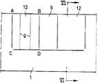
제 1도는 제 2 도의 Ⅰ-Ⅰ 선을 따른 강대의 연속주조 주형의 종단면도이고,1 is a longitudinal sectional view of a continuous casting mold of a steel strip along the line I-I of FIG. 2,
제2도는 연속주조주형의 평면도이고,2 is a plan view of the continuous casting mold,
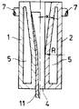
제3도는 제4도의 Ⅲ-Ⅲ선의 방향으로 본 광측벽의 내부도이고,3 is an interior view of the light side wall viewed in the direction of line III-III of FIG. 4,
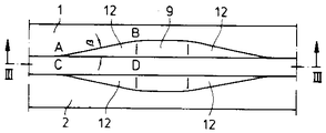
제4도는 주형의 주입영역의 평면도이고,4 is a plan view of the injection region of the mold,
제5도는 다른 천이표면부 윤곽을 가진 광측벽의 내면도이고,5 is an internal view of a light side wall with different transition surface contours
제6도는 제3도 및 제5도의 Ⅵ-Ⅵ선을 따른 천이표면부 영역에서의 주형횡단면도이다.FIG. 6 is a cross-sectional view of the mold in the region of the transition surface along the VI-VI line of FIGS. 3 and 5. FIG.
* 도면의 주요 부분에 대한 부호의 설명* Explanation of symbols for the main parts of the drawings
1,2 : 광측벽 3,4 : 협측벽1,2:
5 : 공동부 9 : 주입영역5: cavity 9: injection area
10 : 주조관 12 : 천이표면부.10: casting tube 12: transition surface portion.
본 발명은 광측벽(廣惻壁)의 영역에 주조관용 주입영역을 형성하기 위해 상향으로 확대되어 있고 주입영역의 옆에 평행단부를 갖고 있는, 냉각된 광측벽과 협측벽(狹惻壁)을 지닌 강대 연속주조주형에 관한 것이다.The present invention provides a cooled light side wall and a narrow side wall which are enlarged upward to have an injection region for a casting pipe in an area of the light side wall and having parallel ends next to the injection area. It is about a continuous casting mold with a large diameter.
이러한 종류의 공지주형에 있어서는, 광측벽은 협측벽을 향하여 그리고 주조방향으로 삼각형상 천이표면부(遷移表面部 : transition surface)에 의해, 주조된 강대의 형상으로 줄어드는 깔대기 형상의 주입영역을 형성한다. 깔대기 형상의 주입영역 옆으로는 광측벽이 강대의 두께에 상당하는 간격으로 각각의 협측벽까지 평행하게 뻗어있다(DE-OS 34 00 220).In known molds of this kind, the optical side wall forms a funnel-shaped injection area that is reduced to the shape of the cast steel by a triangular transition surface toward the narrow side wall and in the casting direction. . Next to the funnel-shaped injection zone, the light side walls extend in parallel to each narrow wall at intervals corresponding to the thickness of the steel strip (DE-OS 34 00 220).
주입영역 내부에서 형성되는 슬램외각(殼)은 삼각형상 주입영역이 대형(帶型)으로 축소될 때 주조방향으로 예각으로 뻗어있는 외연을 통해 심한 휨응력을 받는다. 이 휨응력을 최소화하기 위해 공지의 주형에서는 변형각을 작게하고 있다.The slam shell formed inside the injection zone is subjected to severe bending stress through an outer edge extending at an acute angle in the casting direction when the triangular injection zone is reduced in size. In order to minimize this bending stress, the deformation angle is reduced in a known mold.
본 발명의 과제는 슬램외각이 대형으로 축소될 때 슬램외각의 응력, 주형마모 및 필요한 인출력을 감소시킬 수 잇으며 또한 용융강(鎔融錦)의 측방으로의 분배가 개선될 수 있도록 적절한 형상으로 이루어진 강대 주조용 파쇄안전주형을 제공하는 것이다.The object of the present invention is to reduce the slam shell stress, mold wear and necessary pullout when the slam shell is reduced to a large size, and also to form an appropriate shape so that the distribution of molten steel to the side can be improved. It is to provide a steel shattering safety mold made of.
당 과제는 본 발명에 의하여 주형이 수평선(C-D)을 따라 옆으로 갈수록 작아지는 변형각(α)으로 광측벽의 형태결정(형상을 결정하는) 하부로 뻗는 직사각형의 천이표면부를 갖게 함으로써 해결된다.This problem is solved by the present invention by having a rectangular transition surface portion extending below the shape determination (determining the shape) of the light side wall at a deformation angle α of the mold, which decreases laterally along the horizontal line C-D.
그럼으로써 천이표면부 영역에서의 슬랩외각의 휨팽창이 크게 감소될 수 있다. 본 발명의 새로운 형상은 용융강의 흐름에 유리하게 되어 있어 용융강이 협측벽쪽으로 보다 잘 배분될 수 있다.As a result, the bending expansion of the slab outer shell in the transition surface region can be greatly reduced. The new shape of the present invention favors the flow of molten steel so that the molten steel can be better distributed towards the buccal wall.
또한 만곡부 연결위치에서 그리고 측방 평행부로의 천이가 이루어지는 위치에서 슬랩외각이 주형벽으로부터 이격하여 표면결함이 생기는 것도 피할 수 있다. 이런 방식에 따르면, 주조하기 곤란한 강재도 얇은 대형상으로 주조할 수 있는 가능성이 생긴다.It can also be avoided that the slab shell is spaced apart from the mold wall at the bend connection position and at the transition to the lateral parallels, resulting in surface defects. According to this method, there is a possibility that even steel materials which are difficult to cast can be cast in a thin large phase.
본 발명의 또다른 특징에 의하면 천이표면부의 특히 유리한 윤곽은 직선(A-B) 및 직선(C-D)상의 서로수직위치에 있는 점들을 직선(g)에 의해 연결함으로써 이루어진다.According to another feature of the invention a particularly advantageous contour of the transition surface is achieved by connecting the points at mutually perpendicular positions on straight lines A-B and straight lines C-D by straight lines g.
천이표면부의 또다른 윤곽은 직선(A'-B' 및 B'-D')의 각점을 점(C')과 직선(g')에 의해 방사상으로 연결함으로써 이루어진다.Another contour of the transition surface is achieved by radially connecting each point of the straight lines A'-B 'and B'-D' by a point C 'and a straight line g'.
본 발명의 그 이상의 다른 형상은 특허청구의 범위 제4항과 제5항으로부터 얻어진다.Further other forms of the invention are obtained from
도면에는 본 발명의 실시예가 표시되어 있다.In the drawings, an embodiment of the present invention is shown.
도시된 연속주조 주형에서는 두개의 광측벽(1, 2)과, 상기 광측벽(1, 2)의 평행측부들 사이에 배치된 협측벽(3, 4)이 주형공간을 형성한다(제1도 및 제2도 참조). 또한 냉각된 협측벽(3, 4)은 스핀들(8)에 의해 광측벽(1, 2) 사이에서 위치이동가능하다. 광측벽(1, 2)은 확대된 주입영역(9)을 형성하는데, 그 내부중앙에는 액체강을 공급하는 주조관(10)이 뻗어있다.In the continuous casting mold shown, two
주입영역(9)에서 응고되는 슬랩외각(11)(제6도)은 띠형태로 침강함으로써 그 두께가 감소되어 강대로 변형된다. 그에 따라 발생하는 슬랩외각(11)의 휨팽창을 가능한한 최소화하기 위하여 주입영역의 측면부는 꼭지점(A, B, C, D)을 가진 직사각형 천이표면부(12)로서 형성되어 있다. 광측벽은 하부의 형태결정부에 수평선(C-D)에서부터 천이(transition)된다. 천이표면부(12)의 윤곽은 직선(A-B)와 직선(C-D)상에서 상호수직하게 놓여있는 점들을 서로 연결하고 광측벽(1, 2)의 하부형태결정부에 대하여 위치에 따라 예컨대 10°에서 0°로 감소하는 상이한 변형각(제6도 참조)으로 존재하는 직선들(g)에 의해 형성된다.The slab shell 11 (FIG. 6) which solidifies in the
천이표면부(12)의 직사각형 형상 이하에 따라 주입영역의 개각(β)(제4도 참조)은 주조방향에 따라 연속적으로 감소하여 직선(C-D)에서 0의 값에 도달한다.According to the rectangular shape of the
제5도에 도시된 실시예의 경우, 천이표면부(12')의 윤곽은 점(C')에서 출발하여 수평선(A'-B') 및 수직선(B'-D')의 각점과 방사상으로 연결하는 직선(g')에 의해 형성된다. 여기서 계각(β)은 직선(g')의 대각선위치로부터 직선(C'-D')과의 평행위치까지에 0°에까지 감소된다. 주입영역의 상연은 제4도에서 볼 수 있듯이 궁형(弓形)으로 되어 있다.In the case of the embodiment shown in FIG. 5, the contour of the
제6도에 의하면 사각형 천이표면부(12)는 광측벽(1, 2)의 형태결정부의 하부면에 만곡되어 천이된다.According to FIG. 6, the rectangular
Claims (5)
Applications Claiming Priority (2)
| Application Number | Priority Date | Filing Date | Title |
|---|---|---|---|
| DE3601501A DE3601501C3 (en) | 1986-01-20 | 1986-01-20 | Mold for the continuous casting of steel strip |
| DEP3601501.6 | 1986-01-20 |
Publications (2)
| Publication Number | Publication Date |
|---|---|
| KR870006938A KR870006938A (en) | 1987-08-13 |
| KR950014346B1 true KR950014346B1 (en) | 1995-11-25 |
Family
ID=6292198
Family Applications (1)
| Application Number | Title | Priority Date | Filing Date |
|---|---|---|---|
| KR1019860011639A KR950014346B1 (en) | 1986-01-20 | 1986-12-31 | Ingot mould for continuous casting steel strip |
Country Status (17)
| Country | Link |
|---|---|
| US (1) | US4721151A (en) |
| EP (1) | EP0230886B1 (en) |
| JP (1) | JPH0790331B2 (en) |
| KR (1) | KR950014346B1 (en) |
| CN (1) | CN1006206B (en) |
| AT (1) | ATE58854T1 (en) |
| BR (1) | BR8700219A (en) |
| CA (1) | CA1268314A (en) |
| DD (1) | DD253198A5 (en) |
| DE (2) | DE3601501C3 (en) |
| ES (1) | ES2023121B3 (en) |
| GR (1) | GR3001401T3 (en) |
| IN (1) | IN169294B (en) |
| MX (1) | MX163639B (en) |
| SU (1) | SU1558293A3 (en) |
| UA (1) | UA6338A1 (en) |
| ZA (1) | ZA87222B (en) |
Families Citing this family (11)
| Publication number | Priority date | Publication date | Assignee | Title |
|---|---|---|---|---|
| DE3640525C2 (en) * | 1986-11-27 | 1996-02-15 | Schloemann Siemag Ag | Mold for the continuous casting of steel strip |
| DE3723857A1 (en) * | 1987-07-18 | 1989-01-26 | Schloemann Siemag Ag | CHOCOLATE FOR VERTICAL STEEL STRIP CASTING |
| GB8814331D0 (en) | 1988-06-16 | 1988-07-20 | Davy Distington Ltd | Continuous casting of steel |
| DE4131829C2 (en) * | 1990-10-02 | 1993-10-21 | Mannesmann Ag | Liquid-cooled mold for the continuous casting of steel strands in slab format |
| US5279354A (en) * | 1990-11-30 | 1994-01-18 | Acutus Industries, Inc. | Method of continuous casting with changing of slab width |
| IT1252991B (en) * | 1991-10-31 | 1995-07-10 | Danieli Off Mecc | CONTINUOUS CASTING CRYSTALIZER FOR TONGUE FOR THIN SLABS |
| IT1252990B (en) * | 1991-10-31 | 1995-07-10 | Danieli Off Mecc | LONGITUDINAL BENDING CRYSTALLIZER FOR CONTINUOUS CASTING CURVE FOR THIN BRANKS |
| DE4424600A1 (en) * | 1994-07-13 | 1996-01-18 | Eko Stahl Gmbh | Mould for continuous casting of thin slabs |
| US5850871A (en) * | 1996-04-04 | 1998-12-22 | Ag Industries, Inc. | Foot guide and control system for continuous casting machine |
| DE19853738A1 (en) * | 1998-11-21 | 2000-05-25 | Schloemann Siemag Ag | Mold for the continuous casting of metal |
| US6419005B1 (en) * | 2000-06-29 | 2002-07-16 | Vöest-Alpine Services and Technologies Corporation | Mold cassette and method for continuously casting thin slabs |
Family Cites Families (5)
| Publication number | Priority date | Publication date | Assignee | Title |
|---|---|---|---|---|
| DE887990C (en) * | 1951-05-07 | 1953-08-27 | Irving Rossi | Water-cooled continuous casting mold |
| GB1199805A (en) * | 1967-04-20 | 1970-07-22 | British Iron Steel Research | Continuous Casting |
| JPS59165748U (en) * | 1983-04-23 | 1984-11-07 | 日本鋼管株式会社 | Mold for round billet continuous casting machine |
| DE3400220A1 (en) * | 1984-01-05 | 1985-07-18 | SMS Schloemann-Siemag AG, 4000 Düsseldorf | CHOCOLATE FOR CONTINUOUSLY STEEL STRIP |
| AT379093B (en) * | 1984-02-16 | 1985-11-11 | Voest Alpine Ag | CONTINUOUS CHOCOLATE FOR A CONTINUOUS CASTING SYSTEM |
-
1986
- 1986-01-20 DE DE3601501A patent/DE3601501C3/en not_active Expired - Lifetime
- 1986-12-26 IN IN1015/MAS/86A patent/IN169294B/en unknown
- 1986-12-31 KR KR1019860011639A patent/KR950014346B1/en not_active IP Right Cessation
-
1987
- 1987-01-09 ES ES87100221T patent/ES2023121B3/en not_active Expired - Lifetime
- 1987-01-09 DE DE8787100221T patent/DE3766503D1/en not_active Expired - Lifetime
- 1987-01-09 AT AT87100221T patent/ATE58854T1/en not_active IP Right Cessation
- 1987-01-09 EP EP87100221A patent/EP0230886B1/en not_active Expired - Lifetime
- 1987-01-13 ZA ZA87222A patent/ZA87222B/en unknown
- 1987-01-16 DD DD87299294A patent/DD253198A5/en not_active IP Right Cessation
- 1987-01-19 CA CA000527636A patent/CA1268314A/en not_active Expired - Lifetime
- 1987-01-20 SU SU874028859A patent/SU1558293A3/en active
- 1987-01-20 BR BR8700219A patent/BR8700219A/en not_active IP Right Cessation
- 1987-01-20 UA UA4028859A patent/UA6338A1/en unknown
- 1987-01-20 CN CN87100575.1A patent/CN1006206B/en not_active Expired
- 1987-01-20 MX MX4976A patent/MX163639B/en unknown
- 1987-01-20 JP JP62009184A patent/JPH0790331B2/en not_active Expired - Lifetime
- 1987-01-21 US US07/005,625 patent/US4721151A/en not_active Expired - Lifetime
-
1991
- 1991-01-30 GR GR91400116T patent/GR3001401T3/en unknown
Also Published As
| Publication number | Publication date |
|---|---|
| US4721151A (en) | 1988-01-26 |
| ZA87222B (en) | 1987-08-26 |
| DD253198A5 (en) | 1988-01-13 |
| DE3601501A1 (en) | 1987-07-23 |
| CA1268314A (en) | 1990-05-01 |
| CN1006206B (en) | 1989-12-27 |
| CN87100575A (en) | 1987-08-19 |
| DE3601501C2 (en) | 1995-04-27 |
| JPS62220249A (en) | 1987-09-28 |
| ES2023121B3 (en) | 1992-01-01 |
| DE3601501C3 (en) | 2000-10-05 |
| JPH0790331B2 (en) | 1995-10-04 |
| IN169294B (en) | 1991-09-21 |
| EP0230886B1 (en) | 1990-12-05 |
| UA6338A1 (en) | 1994-12-29 |
| EP0230886A2 (en) | 1987-08-05 |
| DE3766503D1 (en) | 1991-01-17 |
| ATE58854T1 (en) | 1990-12-15 |
| EP0230886A3 (en) | 1987-12-16 |
| MX163639B (en) | 1992-06-10 |
| GR3001401T3 (en) | 1992-09-25 |
| SU1558293A3 (en) | 1990-04-15 |
| BR8700219A (en) | 1987-12-01 |
| KR870006938A (en) | 1987-08-13 |
Similar Documents
| Publication | Publication Date | Title |
|---|---|---|
| KR960004417B1 (en) | Continuous-casting mould for steel strip | |
| KR950014346B1 (en) | Ingot mould for continuous casting steel strip | |
| KR100567749B1 (en) | Improved contact mould for the continuous casting of steel slabs | |
| JP3140592B2 (en) | Mold for continuous casting of steel strip | |
| CN1034559C (en) | Crystallizer of continuous casting of slab ingot | |
| US6186220B1 (en) | Funnel geometry of a mold for the continuous casting of metal | |
| US4565236A (en) | Method of and mold for continuously casting steel beam blanks | |
| US6390176B1 (en) | Funnel geometry of a mold for the continuous casting of metal | |
| EP1716941B1 (en) | Water-cooling mold for metal continuous casting | |
| WO1996035533A1 (en) | Mould for continuous casting | |
| WO1996035532A1 (en) | Mould | |
| RU2156178C2 (en) | Tray to cast flat ingots | |
| JPS6240099B2 (en) | ||
| Jacoby | A Block for Starting the Process of Continuous Casting of Molten Metal | |
| IT9052935U1 (en) | CASTING METAL CUP. | |
| TH38312A (en) | Geometrical cone mold for continuous metal casting |
Legal Events
| Date | Code | Title | Description |
|---|---|---|---|
| A201 | Request for examination | ||
| E902 | Notification of reason for refusal | ||
| G160 | Decision to publish patent application | ||
| E701 | Decision to grant or registration of patent right | ||
| GRNT | Written decision to grant | ||
| FPAY | Annual fee payment |
Payment date: 20061031 Year of fee payment: 12 |
|
| EXPY | Expiration of term |