KR950002933B1 - Slip control system for vehicle and rough road detecting system - Google Patents
Slip control system for vehicle and rough road detecting system Download PDFInfo
- Publication number
- KR950002933B1 KR950002933B1 KR1019910004549A KR910004549A KR950002933B1 KR 950002933 B1 KR950002933 B1 KR 950002933B1 KR 1019910004549 A KR1019910004549 A KR 1019910004549A KR 910004549 A KR910004549 A KR 910004549A KR 950002933 B1 KR950002933 B1 KR 950002933B1
- Authority
- KR
- South Korea
- Prior art keywords
- wheel
- vehicle
- detecting
- driving
- slip
- Prior art date
Links
Images


Classifications
-
- B—PERFORMING OPERATIONS; TRANSPORTING
- B60—VEHICLES IN GENERAL
- B60K—ARRANGEMENT OR MOUNTING OF PROPULSION UNITS OR OF TRANSMISSIONS IN VEHICLES; ARRANGEMENT OR MOUNTING OF PLURAL DIVERSE PRIME-MOVERS IN VEHICLES; AUXILIARY DRIVES FOR VEHICLES; INSTRUMENTATION OR DASHBOARDS FOR VEHICLES; ARRANGEMENTS IN CONNECTION WITH COOLING, AIR INTAKE, GAS EXHAUST OR FUEL SUPPLY OF PROPULSION UNITS IN VEHICLES
- B60K28/00—Safety devices for propulsion-unit control, specially adapted for, or arranged in, vehicles, e.g. preventing fuel supply or ignition in the event of potentially dangerous conditions
- B60K28/10—Safety devices for propulsion-unit control, specially adapted for, or arranged in, vehicles, e.g. preventing fuel supply or ignition in the event of potentially dangerous conditions responsive to conditions relating to the vehicle
- B60K28/16—Safety devices for propulsion-unit control, specially adapted for, or arranged in, vehicles, e.g. preventing fuel supply or ignition in the event of potentially dangerous conditions responsive to conditions relating to the vehicle responsive to, or preventing, skidding of wheels
-
- B—PERFORMING OPERATIONS; TRANSPORTING
- B60—VEHICLES IN GENERAL
- B60T—VEHICLE BRAKE CONTROL SYSTEMS OR PARTS THEREOF; BRAKE CONTROL SYSTEMS OR PARTS THEREOF, IN GENERAL; ARRANGEMENT OF BRAKING ELEMENTS ON VEHICLES IN GENERAL; PORTABLE DEVICES FOR PREVENTING UNWANTED MOVEMENT OF VEHICLES; VEHICLE MODIFICATIONS TO FACILITATE COOLING OF BRAKES
- B60T8/00—Arrangements for adjusting wheel-braking force to meet varying vehicular or ground-surface conditions, e.g. limiting or varying distribution of braking force
- B60T8/17—Using electrical or electronic regulation means to control braking
- B60T8/172—Determining control parameters used in the regulation, e.g. by calculations involving measured or detected parameters
-
- B—PERFORMING OPERATIONS; TRANSPORTING
- B60—VEHICLES IN GENERAL
- B60T—VEHICLE BRAKE CONTROL SYSTEMS OR PARTS THEREOF; BRAKE CONTROL SYSTEMS OR PARTS THEREOF, IN GENERAL; ARRANGEMENT OF BRAKING ELEMENTS ON VEHICLES IN GENERAL; PORTABLE DEVICES FOR PREVENTING UNWANTED MOVEMENT OF VEHICLES; VEHICLE MODIFICATIONS TO FACILITATE COOLING OF BRAKES
- B60T8/00—Arrangements for adjusting wheel-braking force to meet varying vehicular or ground-surface conditions, e.g. limiting or varying distribution of braking force
- B60T8/17—Using electrical or electronic regulation means to control braking
- B60T8/175—Brake regulation specially adapted to prevent excessive wheel spin during vehicle acceleration, e.g. for traction control
-
- B—PERFORMING OPERATIONS; TRANSPORTING
- B60—VEHICLES IN GENERAL
- B60T—VEHICLE BRAKE CONTROL SYSTEMS OR PARTS THEREOF; BRAKE CONTROL SYSTEMS OR PARTS THEREOF, IN GENERAL; ARRANGEMENT OF BRAKING ELEMENTS ON VEHICLES IN GENERAL; PORTABLE DEVICES FOR PREVENTING UNWANTED MOVEMENT OF VEHICLES; VEHICLE MODIFICATIONS TO FACILITATE COOLING OF BRAKES
- B60T2210/00—Detection or estimation of road or environment conditions; Detection or estimation of road shapes
- B60T2210/10—Detection or estimation of road conditions
- B60T2210/14—Rough roads, bad roads, gravel roads
Abstract
내용 없음.No content.
Description
제1도는 본 발명의 제1실시예에 따른 슬립제어장치가 설치되어 있는 차량의 개략도,1 is a schematic diagram of a vehicle in which a slip control device according to a first embodiment of the present invention is installed;
제2도는 기본트랙션제어를 설명하는 시간도표,2 is a time chart illustrating basic traction control;
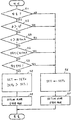
제3도는 제1실시예에 있어 슬립제어장치로 트랙션제어를 실행하는 플로우챠아트,3 is a flowchart art for executing traction control with a slip control apparatus in the first embodiment,
제4도는 차량이 악로를 주행하는지를 판정하는 방법을 설명하는 도면,4 is a diagram for explaining a method for determining whether a vehicle is driving on a bad road,
제5도는 본 발명의 제2실시예에서 슬립제어수단으로서 미끄럼방지제어수단을 사용한 경우, 미끄럼방지제어장치로 미끄럼방지제어를 행한 플로우챠아트,5 is a flowchart showing the non-slip control by the anti-slip control device when the non-slip control means is used as the slip control means in the second embodiment of the present invention.
제6도 및 7도는 본 발명에 따른 장치에 사용할 수 있는 제1실시예의 악로검출장치로 차량이 악로를 주행하는지를 판정하는 방법을 설명한 플로우챠아트,6 and 7 are flowcharts illustrating a method of determining whether a vehicle is driving a bad track by the bad track detection device of the first embodiment which can be used in the apparatus according to the present invention;
제8도 및 9도는 본 발명에 따른 장치에 사용할 수 있는 제2실시예의 악로검출장치로 차량이 악로를 주행하는지를 판정하는 방법을 나타낸 플로우챠아트,8 and 9 are flowcharts illustrating a method for determining whether a vehicle is driving a bad track by the bad track detection device of the second embodiment which can be used in the apparatus according to the present invention;
제10도는 본 발명에 따른 장치에 사용할 수 있는 제3실시예의 악로검출장치로 차량이 악로를 주행하는지를 판정하는 방법을 나타낸 플로우챠아트,10 is a flowchart showing a method of determining whether a vehicle is driving a bad track by the bad track detection apparatus of the third embodiment which can be used in the apparatus according to the present invention;
제11도는 본 발명에 따른 장치에 사용할 수 있는 제4실시예의 악로검출장치로 차량이 악로를 주행하는지를 판정하는 방법을 나타낸 플로우챠아트,11 is a flowchart showing a method of determining whether a vehicle is driving a bad track by the bad track detection apparatus of the fourth embodiment which can be used in the device according to the present invention;
제12도는 본 발명의 제3실시예의 슬립제어장치의 작용을 설명하는 블록도,12 is a block diagram for explaining the operation of the slip control apparatus of the third embodiment of the present invention;
제13도는 슬립제어장치로 트랙션제어를 실행할때의 악로보정을 설명하는 플루오챠아트,Fig. 13 is a fluorocharart for explaining the correction of the frost when performing traction control with a slip control device;
제14도는 슬립제어장치로 미끄럼방지제어를 실행할때의 악로보정을 설명하는 플로우챠아트,Fig. 14 is a flowchart art for explaining bad correction when executing anti-slip control with a slip control device;
제15도는 슬립제어장치가 트랙션제어 및 미끄럼방지제어를 행할 경우의 악로보정을 설명하는 플로우챠아트,FIG. 15 is a flowchart illustrating the music correction process when the slip control device performs traction control and anti-slip control;
제16도 및 17도는 본 발명의 제4실시예의 슬립제어장치의 작용을 설명하는 블록도,16 and 17 are block diagrams for explaining the operation of the slip control apparatus according to the fourth embodiment of the present invention;
제18도는 슬립제어장치로 미끄럼방지제어를 실행하는 플로우챠아트.18 is a flowchart art for performing anti-slip control with a slip control device.
본 발명은 트랙션제어장치 또는 미끄럼방지제어장치와 같은 차량의 슬립제어장치에 관한 것이며, 또한, 차량이 악로 또는 평탄한 길을 주행하는가에 따라 슬립제어방법을 변경시키기 위해 차량이 악로를 주행하는지의 여부를 판정하는 악로검출장치에 관한 것이다.The present invention relates to a slip control device for a vehicle such as a traction control device or an anti-slip control device. Further, the present invention relates to whether or not the vehicle travels the bad track to change the slip control method depending on whether the vehicle travels on the bad track or the flat road. It relates to a bad heart detection device for determining the.
종래부터, 트랙션제어장치 및 미끄럼방지제어장치와 같은 차량의 슬립제어장치가 알려져 있다.Background Art Conventionally, vehicle slip control devices such as traction control devices and anti-slip control devices are known.
트랙션제어에 있어서, 차량의 구동륜의 슬립률을 검출하여, 슬립률이 소정의 임계값(threshold valure)을 초과할 경우, 예를들면 가속시의 구동력이 과도하게 되어 구동륜이 슬립되는 것을 방지하기 위해 구동륜의 슬립률이 목표슬립률로 수렴되도록 엔진출력 및/또는 제동력을 제어함으로써 가속성능을 좋게 한다(엔진출력이 감소 및/또는 제동력이 증가).In traction control, when the slip ratio of the driving wheel of the vehicle is detected and the slip ratio exceeds a predetermined threshold valure, for example, to prevent the driving wheel from slipping due to excessive driving force during acceleration. Acceleration performance is improved by controlling the engine output and / or braking force so that the slip ratio of the drive wheels converges to the target slip rate (the engine output is reduced and / or the braking force is increased).
미끄럼방지제어에 있어서는, 차륜의 슬립률을 검출하여 슬립률이 소정임계값을 초과할 경우, 차륜이 록되는 것을 방지하기 위해 구동륜의 슬립률이 목표슬립률로 수렴되도록 제동력이 조정된다(감소된다).In the anti-slip control, the braking force is adjusted so that the slip ratio of the drive wheel converges to the target slip ratio in order to detect the slip ratio of the wheel and to prevent the wheel from locking when the slip ratio exceeds a predetermined threshold value. ).
일반적으로, 각각의 차륜의 슬립률은 차륜의 원주속도에 따라 결정된다. 따라서, 트랙션제어장치의 경우, 차량이 악로를 주행하고 노면의 요철(凹凸)로 인해 각 차륜의 원주속도가 변동될 경우, 슬립률은 종종 소정의 임계값을 초과하여 차량의 주행상태가 트랙션제어를 필요로 하지 않을 경우에도 트랙션제어가 행해짐으로써 구동력이 감소되어 가속성능이 떨어지는 일이 있다.In general, the slip ratio of each wheel is determined according to the circumferential speed of the wheel. Therefore, in the case of the traction control apparatus, when the vehicle travels in a bad lane and the circumferential speed of each wheel is changed due to the unevenness of the road surface, the slip ratio often exceeds a predetermined threshold so that the running state of the vehicle is in traction control. Even when it is not necessary, the traction control is performed, whereby the driving force is reduced, and acceleration performance may be lowered.
미끄럼방지제어장치에 있어서는, 차량이 악로를 주행하는 동안 미끄럼방지제어가 실행되어 슬립률이 목표슬립률에 수렴할때보다 차륜을 록경향으로해서 차륜이 노면의 요철에 걸치도록 하는 편이 더욱 유효한 제동이 일어날 수 있다.In the anti-skid control device, it is more effective to prevent the non-slip control while the vehicle travels in a bad lane so that the wheels are locked against the road surface by turning the wheels in a lock direction than when the slip ratio converges to the target slip rate. This can happen.
즉, 트랙션제어 및 미끄럼방지제어에 있어서, 차량이 평탄한 길을 주행할 경우보다 차량이 악로를 주행할 경우에 임계슬립률을 일정범위로 높임으로써 트랙션제어 또는 미끄럼방지제어가 덜 실행되도록 하는 것이 바람직하다.That is, in the traction control and the anti-slip control, it is preferable that the traction control or the anti-slip control is performed less by increasing the threshold slip rate to a certain range when the vehicle travels in a bad lane than when the vehicle travels on a flat road. Do.
차량이 악로를 주행할때의 임계슬립률을 변경 또는 보정하기 위해서, 차량이 악로를 주행하는지의 여부를 판정해야만 한다. 차량이 악로를 주행할때의 임계슬립률을 보정하는 것을 이하 "악로보정"이라 칭하며, 차량이 악로를 주행하는 것을 검출하는 수단을 "악로검출수단" 또는 "악로검출장치"라 한다.In order to change or correct the critical slip rate when the vehicle is traveling on the track, it is necessary to determine whether the vehicle is driving on the track. Correcting the critical slip rate when the vehicle travels on the track is referred to as " correction correction " below, and the means for detecting the vehicle traveling on the track is referred to as " error detection means " or " error detection device ".
악로검출장치에 대해서는 예를들면 일본국 특개소 NO.64(1989)-29636호에 개시되어 있다.For example, a defect detection apparatus is disclosed in Japanese Patent Laid-Open No. 64 (1989) -29636.
그러나, 구동륜에 대하여, 차량이 악로를 주행하고 있을때악로보정을 행하는 것이 항상 바람직한 것은 아니다. 즉, 구동륜에 대하여, 악로보정은 차량의 주행상태(예를들면, 조타상태, 차량속도, 가속기페달의 답입량, 주행모우드등)에 따라 실행되는 것이 아니다.However, with respect to the drive wheels, it is not always desirable to perform the course correction when the vehicle is traveling on the trail. That is, with respect to the drive wheels, the course correction is not performed in accordance with the driving state of the vehicle (for example, the steering state, the vehicle speed, the depression amount of the accelerator pedal, the driving mode, etc.).
또한, 악로보정의 내용, 예를들면, 얼마만큼의 임계슬립률이 증가하는가는 차량의 주행상태에 따라 결정된다.In addition, the contents of the course correction, for example, how much the critical slip rate increases is determined according to the driving state of the vehicle.
전술한 관찰 및 설명에 비추어, 본 발명의 주목적은 차량의 주행상태에 무관하게 최적의 방법으로 악로보정을 실행할 수 있는 슬립제어장치를 제공하는 것이다.In view of the foregoing observations and explanations, the main object of the present invention is to provide a slip control apparatus capable of performing bad track correction in an optimal manner irrespective of the driving state of the vehicle.
본 발명의 다른 목적은 슬립제어장치에 최적으로 사용할 수 있고 차량의 주행상태, 차량의 서스펜션 특성등에 영향을 받지 않으면서 차량이 악로를 주행하는지의 여부를 정확하게 판정할 수 있는 악로검출장치를 제공하는 것이다.It is another object of the present invention to provide an ear detection apparatus which can be optimally used in a slip control device and can accurately determine whether a vehicle is traveling in a bad road without being influenced by the driving state of the vehicle, the suspension characteristics of the vehicle, and the like. will be.
본 발명의 한측면에 의하면, 차량구동륜의 슬립률을 검출하는 슬립률검출수단, 슬립률검출수단에 의해 검출된 구동륜의 슬립률이 소정의 임계슬립률을 초과할 경우에 구동륜의 슬립률이 소정의 목표슬립률로 수렴하도록 구동륜의 슬립을 소정의 조정된 변수로 제어하는 구동륜슬립제어수단, 차량이 악로를 주행하는지의 여부를 판정하는 악로검출수단, 악로검출수단으로 차량이 악로를 주행할때를 판정할 경우 주어진 슬립률에서 구동륜상에 슬립제어장치의 제어를 덜 실행시키도록 하는 악로보정수단, 차량의 주행상태를 검출하는 주행상태검출수단 및, 주행상태검출수단으로 검출한 주행상태에 의거하여 악로보정수단을 제어하는 악로보정제어수단으로 이루어지는 차량의 슬립제어장치를 제공한다.According to one aspect of the present invention, the slip ratio of the driving wheel is predetermined when the slip ratio of the slip ratio detecting means for detecting the slip ratio of the vehicle drive wheel and the slip ratio of the driving wheel detected by the slip ratio detecting means exceeds a predetermined threshold slip ratio. Driving wheel slip control means for controlling the slip of the driving wheel to a predetermined adjusted variable so as to converge at a target slip rate of the vehicle; On the basis of the driving condition detecting means for less controlling of the slip control device on the driving wheel at the given slip rate, the driving state detecting means for detecting the driving state of the vehicle, and the driving state detected by the driving state detecting means. There is provided a slip control apparatus for a vehicle, which is composed of an evil correction control means for controlling the evil correction means.
본 명세서에 있어서, "주어진 슬립률에서 구동륜상에 슬립제어장치의 제어를 덜 실행시키도록 한다"라고 하는것은 "구동륜의 슬립률이 상기 소정임계슬립률보다 높은 임계슬립률을 초과할 때까지 슬립제어수단이 제어를 시작하지 않는 것"과 "구동륜의 소정임계슬립률을 초과할 경우 슬립제어 수단이 제어를 시작할지라도 주어진 슬립률에서 구동륜상에 슬립제어수단의 제어의 효과를 감소시키는 것"을 포함하여 넓게 해석된다.In the present specification, "to make less control of the slip control device on the drive wheel at a given slip rate" means "slip until the slip rate of the drive wheel exceeds a threshold slip rate higher than the predetermined threshold slip rate. The control means not to start control "and" reducing the effect of the control of the slip control means on the drive wheel at a given slip rate even if the slip control means starts control if the predetermined threshold slip rate of the drive wheel is exceeded. " Including broadly interpreted.
예를들면, 악로보정수단은 목표슬립률 또는 소정임계슬립률을 증가시키거나 조정된 변수를 감소시킬 수 있다.For example, the course correction means may increase the target slip rate or the predetermined threshold slip rate or decrease the adjusted variable.
차량의 주행상태란 요우레이트(yaw rate), 조타각도, 차량속도, 가속기페탈의답입량, 주행모오드(정상모오드 또는 소프트모오드(Sport mode)등의 트랙션제어 모오드)등을 의미한다.The driving state of the vehicle means a yaw rate, a steering angle, a vehicle speed, an amount of accelerator pedal depression, a driving mode (a traction control mode such as a normal mode or a soft mode).
상기 설명한 바와같이, 트랙션제어시에 악로보정이 실행되면, 커다란 구동토오크가 차륜에 전달되어 차륜으로부터 도로표면상에 작용하는 구동력 또한 증가한다. 차륜으로부터 도로표면상에 작용하는 구동력이 증가하면, 도로그립(grip)력은 감소한다. 또한 미끄럼방지제어시에 악로보정이 실행될 경우, 차륜은 록되기 쉽고, 구동륜이 록으로될 경우, 차체거동은 변한다. 즉, 어느 제어에 있어서도 악로보정을 실행할 경우 차량의 안정성이 떨어진다.As described above, when the course correction is performed during the traction control, a large driving torque is transmitted to the wheels and the driving force acting on the road surface from the wheels also increases. As the driving force acting on the road surface from the wheel increases, the grip force decreases. In addition, when the bad correction is performed during the anti-slip control, the wheel is easily locked, and when the driving wheel is locked, the body behavior changes. That is, in any control, when the bad correction is performed, the stability of the vehicle is lowered.
차량이 악로를 선회하거나 차량이 악로를 고속으로 주행할 경우에, 차체의 자세는 횡방향으로 변화되기 쉽다. 따라서, 조타각도 또는 요우레이트가 클 경우나 차량속도가 높은 경우에는 악로보정을 행하지 않는것이 바람직하다.When the vehicle turns the lane or the vehicle drives the lane at high speed, the attitude of the vehicle body tends to change laterally. Therefore, it is preferable not to perform the course correction when the steering angle or the yaw rate is large or when the vehicle speed is high.
본 발명의 다른 측면에 의하면, 차륜의 가속을 검출하는 차륜가속검출수단, 단위 시간내 차륜의 가속이 소정임계값이상으로 진동하는 주파수를 소정주파수와 비교해서 전자가 후자보다 클경우 차량이 악로를 주행한다고 판정하는 비교수단, 차륜에 대한 브레이크의 적용을 검출하는 제동검출수단, 및 차륜에 제동이 행해졌는지의 여부에 따라 임계값을 변화시켜서 차륜에 제동이 가해지지 않았을 때보다 차륜에 제동이 가해진때임계값이 크게 되는 임계값 변경수단으르 이루어지는, 차륜이 악로를 주행하는지의 여부를 검출하는 악로검출장치를 제공한다.According to another aspect of the invention, the wheel acceleration detection means for detecting the acceleration of the wheel, the vehicle is a bad road when the former is greater than the latter by comparing the frequency at which the acceleration of the wheel in the unit time oscillates more than the predetermined threshold value with the predetermined frequency Comparison means for determining that the vehicle is traveling, brake detection means for detecting the application of the brake to the wheel, and the threshold value is changed according to whether or not the brake is applied to the wheel, and braking is applied to the wheel than when the brake is not applied to the wheel. Provided is a fault detection apparatus for detecting whether or not a wheel travels a bad track, wherein the threshold value changing means has a large threshold value.
제동시, 차륜가속도의 진동진폭은 확대되며, 따라서, 차륜에 제동을 가하는 동안 임계값을 확대함으로써 차륜이 악로를 주행하는지의 여부를 제동에 의한 진폭증가에 영향을 받지 않고 정밀하게 검출할 수 있다.During braking, the vibration amplitude of the wheel acceleration is increased, and thus, by increasing the threshold value during braking of the wheel, it is possible to precisely detect whether the wheel is driving in a bad road without being affected by the increase in amplitude due to braking. .
본 발명의 다른 측면에 의하면, 차량의 전, 후륜의 속도변화를 검출하는 차륜 속도변화검출수단, 차륜에 대한 브레이크의 적용을 검출하는 제동검출수단, 및 전, 후륜중의 적어도 하나의 속도변화에 의거하여 차량이 악로를 주행하는지의 여부를 판정하는 판정수단으로 이루어지고, 상기 판정수단이 적어도 전, 후륜에 제동이 가해질때 후륜의 속도변화에 의거하여 차량이 악로를 주행하는지의 여부를 판정하는 것을 특징으로 하는, 차량이 악로를 주행하는지의 여부를 검출하는 악로검출장치를 제공한다.According to another aspect of the invention, the wheel speed change detection means for detecting a change in the speed of the front and rear wheels of the vehicle, the braking detection means for detecting the application of the brake to the wheel, and at least one speed change of the front and rear wheels And determining means for determining whether or not the vehicle is driving on the track based on the speed change of the rear wheels when braking is applied to at least the front and rear wheels. An error detection apparatus for detecting whether or not a vehicle travels a lane is provided.
일반적으로, 구동륜의 속도는 구동토오크의 변동에 의해 더욱 영향을 받기 쉽다. 따라서, 차속의 변화에 의거하여 차량이 악로를 주행하는지의 여부를 판정할 경우, 종동차륜의 차속변화에 의거하여 판정하는 것이 바람직하다. 그러나, 일반적으로 브레이크는 후륜보다 전륜에 더욱 효과적으로 제동이 행해지게 배치되어 있고 따라서 전륜이 제동력변동에 의해 더욱 쉽게 영향을 받는 동시에, 전륜은 더욱 쉽게 록되므로, 후륜이 구동륜인지의 여부에 무관하게 제동이 가해질 경우 후륜의 차속 변화에 의거하여 차량이 악로를 주행하는지의 여부를 판정하는 것이 바람직하다.In general, the speed of the drive wheels is more susceptible to fluctuations in drive torque. Therefore, when determining whether or not the vehicle travels on the road based on the change in the vehicle speed, it is preferable to make the determination based on the change in the vehicle speed of the driven wheel. However, in general, the brake is arranged to brake the front wheel more effectively than the rear wheel, so that the front wheel is more easily affected by the braking force variation, and the front wheel is more easily locked, thus braking regardless of whether the rear wheel is the driving wheel. In this case, it is preferable to determine whether or not the vehicle is traveling on the road based on the change of the vehicle speed of the rear wheel.
본 발명의 또다른 측면에 의하면, 차륜의 가속을 검출하는 차륜가속검출수단, 단위시간내 차륜의 가속이 소정임계값이상으로 진동하는 주파수를 소정임계주파수와 비교해서 전자가 후자보다 클 경우 차량이 악로를 주행한다고 판정하는 비교수단, 차륜의 서스펜션의 스프링상수를 검출하는 스프링상수검출수단, 및 스프링상수증가에 따라 임계주파수를 증가시키는 임계주파수변경수단으로 이루어지는, 차륜이 악로를 주행하는지의 여부를 검출하는 악로검출장치를 제공한다.According to another aspect of the present invention, the wheel acceleration detecting means for detecting the acceleration of the wheel, the vehicle when the former is greater than the latter by comparing the frequency at which the acceleration of the wheel in the unit time oscillates more than the predetermined threshold value with the predetermined threshold frequency Whether or not the wheel travels on the track, comprising: comparison means for determining that the track runs, a spring constant detection means for detecting the spring constant of the suspension of the wheel, and a threshold frequency changing means for increasing the threshold frequency according to the increase of the spring constant; An apparatus for detecting evils is provided.
차륜의 진동주기는 짧게 됨으로써 서스펜션의 스프링 상수증가에 따라 차륜가속도의 진동주지는 짧게 된다. 따라서, 서스펜션의 스프링상수의 증가에 따라서 임계주파수를 증가시킴으로서, 차량이 악로를 주행하는지의 여부를 서스펜션의 스프링상수 변경에 기인한 차륜가속의 진동주기의 변경에 영향받지 않고 정밀하게 검출할 수 있다.As the vibration period of the wheel is shortened, the vibration acceleration of the wheel acceleration becomes shorter as the spring constant of the suspension increases. Therefore, by increasing the critical frequency in accordance with the increase of the spring constant of the suspension, it is possible to accurately detect whether or not the vehicle travels on the track without being influenced by the change of the vibration period of the wheel acceleration due to the change of the spring constant of the suspension. .
본 발명의 또다른 측면에 의하면, 차륜의 가속을 검출하는 차륜가속검출수단, 단위시간내 차륜의 가속도가 소정임계값이상으로 진동하는 주파수를 소정임계주파수와 비교해서 전자가 후자보다 클경우 차량이 악로를 주행하고 있다고 판정하는 비교수단, 차륜의 서스펜션의 감쇠력을 검출하는 감쇠력검출수단 및, 감쇠력의 증가에 따라서 임계값을 감소시키는 임계값 변경수단으로 이루어지는, 차륜이 악로를 주행하는지의 여부를 검출하는 악로검출장치를 제공한다.According to another aspect of the present invention, the wheel acceleration detecting means for detecting the acceleration of the wheel, the vehicle when the former is greater than the latter by comparing the frequency at which the acceleration of the wheel in the unit time oscillates more than the predetermined threshold value with the predetermined threshold frequency Detecting whether or not the wheel is driving the bad track, comprising: comparing means for determining that the bad road is being driven, damping force detecting means for detecting the damping force of the suspension of the wheel, and threshold changing means for decreasing the threshold value as the damping force is increased Provided is a bad heart detection device.
차륜의 진동진폭은 작게 됨으로써 서스펜션의 감쇠력의 증가에 따라서 차륜가속도의 진동진폭은 작아진다. 따라서, 서스펜션의 감쇠력증가에 따라서 임계값을 감소시킴으로써, 차량이 악로를 주행하는지의 여부를 서스펜션의 감쇠력의 변경에 기인한 차륜가속도의 진동진폭의 변경에 영향받지 않고 정확하게 검출할 수 있다.As the vibration amplitude of the wheel decreases, the vibration amplitude of the wheel acceleration decreases as the damping force of the suspension increases. Therefore, by decreasing the threshold value in accordance with the increase in the damping force of the suspension, it is possible to accurately detect whether or not the vehicle travels on the track without being affected by the change in the vibration amplitude of the wheel acceleration due to the change in the damping force of the suspension.
본 발명의 또다른 측면에 의하면, 차량의 전, 후륜의 슬립을 제어하는 슬립제어수단, 좌측차륜의 속도변경에 의거하여 좌측차륜이 악로를 주행하는지의 여부를 검출하는 좌측악로검수출수단, 우측차륜의 속도변화에 의거하여 우측차륜이 악로를 주행하는지의 여부를 검출하는 우측악로검출수단, 좌, 우측악로검출수단중의 적어도 하나가 차륜이 악로를 주행하고 있다는 것을 검출할 경우, 차량이 악로를 주행하고 있다는 판정하는 제1판정수단, 좌, 우측악로검출수단이 둘다 차륜이 악로를 주행하고 있다는 것을 검출한 경우 차량이 악로를 주행하고 있다고 판정하는 제2판정수단, 및 차량의 주행상태 또는 슬립제어수단으로 실행되는 슬립제어의 종류에 따라 제1, 제2판정수단중의 하나를 선택하고 선택된 판정수단이 차량이 악로를 주행하고 있다고 판정할 경우 슬립제어수단으로 실행되는 슬립제어의 내용을 변경시키는 악로보정수단으로 이루어지는, 차량의 슬립제어장치를 제공한다.According to another aspect of the invention, the slip control means for controlling the slip of the front and rear wheels of the vehicle, the left evil track detection means for detecting whether or not the left wheel is driving on the basis of the speed change of the left wheel, When at least one of the right evil detection means and the left and right evil detection means for detecting whether the right wheel drives the bad track based on the speed change of the right wheel detects that the wheel is driving the bad track, The second judging means for judging that the vehicle is driving the bad lane when the first judging means for judging that the vehicle is driving the bad lane, the left and right evil detection means both detect that the wheel is driving the bad lane, and the vehicle. Select one of the first and second determination means according to the driving state of the vehicle or the type of the slip control executed by the slip control means, and the selected determination means indicates that the vehicle is driving If set consisting of akro correction means for changing the contents of the slip control executed by the slip control means, there is provided a slip control device for a vehicle.
양쪽의 좌, 우륜 모두 악로를 주행할 경우 악로보정을 실행하는 것과 좌, 우륜중의 한쪽만이 주행할 경우에도 악로보정을 실행하는 것중 어느쪽이 더 좋은가는 슬립제어에 의해 실행되는 슬립제어의 종류 또는 차량의 주행상태에 따라 다르다.The slip control is performed by slip control, which is better to perform the course correction when driving on both left and right wheels, or to perform the course correction when only one of the left and right wheels is traveling. It depends on the type or driving condition of the vehicle.
따라서, 차량의 주행상태 또는 슬립제어수단으로 실행되는 슬립제어의 종류에 따라 제1, 제2판정수단중의 하나를 선택함으로써 차량의 주행상태 또는 슬립제어의 종류에 무관하게 최적의 악로보정을 실현할 수 있다.Therefore, by selecting one of the first and second determination means in accordance with the driving state of the vehicle or the type of slip control executed by the slip control means, the optimum course correction can be realized regardless of the driving state of the vehicle or the type of slip control. Can be.
이하, 도면을 참조하면서 본 발명을 상세히 설명한다.Hereinafter, the present invention will be described in detail with reference to the drawings.
제1도에 있어서, 차량(A)에는 슬립제어수단으로서 트랙션제어수단이 장착되어 있다. 이 차량(A)은 그의 앞쪽부분에 장착된 엔진(2)을 가지며, 이 엔진(2)의 출력토오크는 자동변속기(3), 프로펠러축(4), 차동장치(5) 및 좌우구동축(6L), (6R)에 의해 좌우후륜(1RL), (1RR)에 전달된다. 즉, 이 차량(A)은 프런트엔진 리어드라이브차량(front-engine rear-drive vehicle) 이다. (1FL), (1FR)은 각각 좌우전륜을 나타낸다.In Fig. 1, the vehicle A is equipped with traction control means as slip control means. The vehicle A has an
자동변속기(3)는 토오크변환기(11)와 다단변속기어기구(12)로 구성되어 있다. 기어변속은, 변속기어기구(12)의 유압제어회로에 내장된 복수개의 솔레노이드(13a)를 선택적으로 여자 및 소자시키므로써 행해진다. 또한, 토오크변환기(11)는, 유압작동식의 록업클러치(11a)를 가지며, 솔레노이드(13d)의 여자 및 소자에 의해 체결 및 체결해제가 행해진다.The
상기 솔레노이드(13a), (13b)는 자동변속기용의 제어유닛(UAT)에 의해 제어된다. 공지된 바와같이, 이 자동변속기용의 제어유닛(UAT)은, 메인드로틀개방도센서(61)에 의해 검출되는(후술하는)메인드로틀밸브(43)의 개도를 나타내는 메인드로틀개도 신호와, 서브드로틀개도센서(62)에 의해 검출되는(후술하는)서브드로틀밸브(45)의 개도를 나타내는 서브드로틀개도신호와, 차속센서(63)에 의해 검출되는 차속(본 특정실시예에 있어서는 프로펠러축(4)의 회전속도)을 나타내는 차속신호에 의거해서 소정의 변속패턴과 소정의 록업특성에 따라 솔레노이드(13a), (13b)를 제어한다.The solenoids 13a and 13b are controlled by a control unit UAT for an automatic transmission. As is known, the control unit UAT for the automatic transmission includes a main throttle opening degree signal indicating an opening degree of the
각 차륜(1FL), (1FR), (1RL) 및 (1RR)에는 브레이크(21FL), (21FR), (21RL) 및 (21RR)가 설치되어 있다. 각 브레이크(21FL), (21FR), (21RL) 및 (21RR)는 각 브레이크배관(23FL), (23FR), (23RL) 및 (23RR)을 개재하여 브레이크유압을 공급하는 차륜실린더(캘리퍼)(22FL), (22FR), (22RL) 및 (22RR)를 구비하고 있다.Each wheel 1FL, 1FR, 1RL, and 1RR is provided with brakes 21FL, 21FR, 21RL, and 21RR. Each brake 21FL, 21FR, 21RL, and 21RR is a wheel cylinder (caliper) for supplying brake hydraulic pressure through each brake pipe 23FL, 23FR, 23RL, and 23RR ( 22FL), (22FR), (22RL), and (22RR).
브레이크페달(25)은 동력브레이크부우스터(26)를 경유하여 텐뎀마스터실린더(27)와 연결되어 있다. 이 마스터실린더(27)에 의해 생성된 브레이크유압은, 마스터실린더(27)의 제1배출구(27a)와 연결된 브레이크배관(23FL)을 경유하여 좌측전륜브레이크(21FL)에, 이 마스터실린더(27)의 제2배출구(27b)와 연결된 브레이크배관(23FR)을 경유하여 우측전륜브레이크(21FR)에 전달된다.The
작동유압은 배관(28)을 개재해서 펌프(29)로부터 부우스터(26)로 공급되고, 초과작동액은 리터언용 배관(30)을 통해서 저장통(31)으로 복귀된다. 상기 배관(32)으로부터 분기관(28a)이 분기되어 있고, 이 분기관(28a)에는 전자식의 개폐밸브(32)가 설치되어 있다. 배관(33)이 부우스터(26)로부터 뻗어 있고, 이 배관(33)에는 전자식의 개폐밸브(34)가 설착되어 있다. 배관(33)에는 전자식의 개폐밸브(34)와 병렬로 일방향밸브(35)가 접속되어 있다.The hydraulic pressure is supplied from the pump 29 to the
분기관(28a)은 합류부(33a)에서 배관(33)에 접속되어 있으며, 이 합류뷰(33a)에 대해서, 좌우후륜용의 브레이크배관(23RL), (23RP) 이 접속되어 있다. 이 브레이크배관(23RL), (23RR)에는 각각 전자식개폐밸브(36A), (37A)가 설치되어 있고, 이 개폐밸브(36A), (37A)의 하류에 릴리이프통로(38L), (38R)가 각각 브레이크배관(23RL), (23RR)과 접속되어 있다. 이 릴리이프통로(38L), (38R)에는 각각 전자식개폐밸브(36B), (37B)가 설치되어 있다.The branch pipe 28a is connected to the
상기 밸브(32), (34), (36A), (37A), (36B) 및 (37B)는, 슬립제어유닛(UTR)에 의해서 제어된다. 즉, 브레이크제어에 의한 트랙션제어가 행해지지 않으면, 트랙션 제어유닛(UTR)은 밸브(32)를 폐쇄하고, 밸브(34)를 개방하며, 밸브(36B), (37B)를 폐쇄하고, 밸브(36A), (37A)를 개방한다.The
브레이크페달(25)을 이상태에서 밝으면, 전륜용브레이크(21FL), (21FR)에 대해서는 마스터실린더(27)를 개재하여 브레이크유압을 공급하고, 후륜용브레이크(21RL), (21RR)에 대해서는 브레이크유압으로서 부우스터(26)의 작동유압을 공급한다.If the
후술하는 바와같이, 브레이크제어에 의한 트랙션제어가 행해지도록 후륜(1RR),(1RL)(구동륜)의 슬립률이 증가하면, 트랙션제어유닛(UTR)은 밸브(34)를 폐쇄하고 밸브(32)를 개방한다. 그래서, 밸브(36A), (36B), (37A) 및 (37B)의 듀티제어에 의해서, 트랙션제어유닛(UTR)은 그때의 압력으로 브레이크유압을 일정하게 유지하거나, 승압 또는 감압한다. 즉, 밸브(32)가 폐쇄되어 있는 한, 브레이크유압은, 밸브(36A), (36B), (37A), (37B)가 모두 폐쇄되어 있는 경우 일정하게 유지되고, 밸브(36A), (37A)가 개방되고 밸브(36B), (37B)가 폐쇄되면 승압되며, 밸브(36B), (37B)가 개방되고 밸브(36A), (37A)가 폐쇄되면 감압된다. 분기관(28A)을 통해서 전달된 브레이크유압은, 일방향밸브(35)의 작용에 의해 브레이크페달(25)에 대한 반력으로서 작용하지 않도록 되어 있다.As will be described later, when the slip ratios of the rear wheels 1RR and 1RL (drive wheels) increase so that the traction control by the brake control is performed, the traction control unit UTR closes the
이와같은 브레이크제어에 의한 트랙션제어를 행하고 있는 동안 브레이크폐달(25)을 밟으면, 브레이크유압은 이 브레이크페달(25)의 답입량에 따라 부우스터(26)로부터 일방향밸브(35)를 개재해서 후륜용브레이크(21RL), (21RR)에 공급된다.When the
트랙션제어유닛(UTR)은, 브레이크제어에 의한 트랙션제어에 부가해서 엔진출력의 제어에 의해 트랙션제어를 행한다. 이때문에, 흡기통로(41)에는, 가속기페달(42)에 연결된 메인드로틀밸브(43)와, 작동기(44)에 연결된 서브드로틀밸브(45)가 설치되어 있다. 상기 서브드로틀밸브(45)는 작동기(44)를 개재해서 상기 트랙션제어유닛(UTR)에 의해 제어된다.The traction control unit UTR performs traction control by controlling engine output in addition to traction control by brake control. For this reason, the
상기 트랙션제어유닛(UTR)에는, 각각의 차륜(1FL), (1FR), (1RL) 및 (1RR)의 속도를 검출하기 위한 차륜센서(64)∼(67)로부터의 출력신호가 입력되는 외에, 메인드로틀개도센서(61)로부터의 메인드로틀개도신호, 서브드로틀개도센서(62)로부터의 서브드로틀개도신호, 차속센서(63)로부터의 차속신호, 가속기페달(42)의 답입량을 검출하는 가속기위치센서(68)로부터의 가속기위치신호, 요우레이트센서(69)로부터의 요우레이트신호, 시프트위치센서(70)로부터의 시프트위치신호, 조타각센서(71)로부터의 조타각신호 및 수동으로 조작되는 모우드선택스위치(72)로부터의 모우드신호가 입력된다.The traction control unit UTR is inputted with an output signal from the
또한, 트랙션제어유닛(UTR)은, 상기 각 신호를 수용하는 입력인터페이스와, CPU, 롬(ROM) 및 램(RAM)으로 이루어진 마이크로컴퓨투터와, 출력인터페이스와, 밸브(32), (34), (36A), (26B), (37A), (36B), (37B) 및 작동기(44)를 구동하는 구동회로로 구성되어 있다. 롬에는 트랙션제어에 필요한 제어프로그램 및 각종 맵이 격납되어 있으며, 램에는 제어에 필요한 다양한 메모리가 구비되어 있다.The traction control unit UTR further includes an input interface for receiving the respective signals, a microcomputer consisting of a CPU, a ROM, and a RAM, an output interface, a
다음에, 트랙션제어유닛(UTR)에 의해 행해지는 트랙선제어를 제2도를 참조하면서 설명한다.Next, the track line control performed by the traction control unit UTR will be described with reference to FIG.
제2도에 있어서, SET는 엔진출력제어에 의해 트랙션제어를 개시하기 위한 제1임계슬립률이고, SBT는 브레이크제어에 의해 트랙션제어를 개시하기 위한 제2임계슬립률이다. 즉, 구동륜의 슬립률이 제1임계슬립률(SET)을 초과하면, 트랙션 제어유닛(UTR)은 엔진출력제어를 개시하고, 구동륜의 슬립률이 제2임계슬립률(SBT)을 초과하면, 트랙션제어유닛(UTR)은 브레이크제어를 개시한다. 제2임계슬립률(SBT)은 제1임계슬립률(SET)보다 크다. 본 실시예에 있어서, 슬립률이 제1임계슬립률(SET)을 초과하면, 트랙션제어유닛(UTR)은 구동륜의 슬립률이 제1임계슬립률(SET)과 동일한 제1목표슬립률에 수렴하도록 엔진출력을 제어하고, 슬립률이 제2임계슬립률(SBT)을 초과하면, 트랙션제어유닛(UTR)은 슬립률이 제2임계슬림률(SBT)과 동일한 제2목표 슬립률에 수렴하도록 브레이크를 제어한다. 따라서, 이하 SET는 종종 제1임계슬립률(SET) 또는 제1목표슬립률을 나타내며, SBT는 종종 제1임계슬립률(SBT) 또는 제2목표슬립률을 나타낸다.In FIG. 2, SET is a first threshold slip rate for starting traction control by engine output control, and SBT is a second threshold slip rate for starting traction control by brake control. That is, when the slip ratio of the drive wheel exceeds the first critical slip rate SET, the traction control unit UTR starts the engine output control, and when the slip rate of the drive wheel exceeds the second critical slip rate SBT, The traction control unit UTR starts brake control. The second critical slip rate SBT is greater than the first critical slip rate SET. In the present embodiment, if the slip ratio exceeds the first critical slip ratio SET, the traction control unit UTR converges to the first target slip ratio at which the slip ratio of the drive wheel is equal to the first critical slip ratio SET. The engine output is controlled so that the slip rate exceeds the second critical slip rate SBT, the traction control unit UTR causes the slip rate to converge to a second target slip rate equal to the second critical slim rate SBT. Control the brake Thus, the following SET often indicates the first critical slip rate (SET) or the first target slip rate, and SBT often indicates the first critical slip rate (SBT) or the second target slip rate.
제2도에 있어서, 시간(t1)까지는, 구동륜의 슬립률이 그다지 크지 않으므로, 엔진출력제어는 실행되지 않고, 서브드로틀밸브(45)가 많이 개방된 상대를 유지한다. 엔진출력제어가 실행되지 않는 동안, (메인드로틀밸브(43)와 서브드로틀밸브(45)의 개도중 보다 작은 것에 의해 지배되는)유효드로틀개도(Tn)는 메인드로틀밸브(43)의 개도(TH-M) 및 가속기페달(42)의 딥입량에 대응한다.In FIG. 2, since the slip ratio of the drive wheel is not so large until the time t1, the engine output control is not executed and the
구동륜의 슬립률이 제1임계슬립률(SET)을 초과하면, 트렉션제어유닛(UTR)은 출력제어를 개시하여 작동기(44)가 서브드로틀밸브(45)를 폐쇄하도록 하므로써, 유효드로틀개도(Tn)는 갑자기 하한제어값(SM)으로 감소된다. 그후, 트랙션제어유닛(UTR)은 구동륜의 슬립률이 제1목표슬립률(SET)에 수렴되도록 서브드로틀밸브개도(TH-S)를 피이드백 제어한다. 엔진출력제어의 개시후에, 서브드로틀밸브개도(TH-S)는 메인드로틀밸브개도(TH-M)보다 작게 되므로, 유효드로틀개도(Tn)는 서브드로틀밸브개도(TH-S)와 같게 된다.When the slip ratio of the drive wheel exceeds the first critical slip ratio SET, the traction control unit UTR starts output control to cause the actuator 44 to close the
슬립률을 엔진출력제어에 의해서만 충분히 감소시킬 수 없는 경우, 슬립률은 계속 증가하여 시간(t2)에서 제2임계슬립률을 초과하게 된다.If the slip rate cannot be sufficiently reduced only by the engine output control, the slip rate continues to increase to exceed the second critical slip rate at time t2.
구동륜의 슬립률이 제2임계슬립률(SBT)을 초과하면, 트랙션제어유닛(UTR)은 엔진출력제어에 부가해서 브레이크제어를 개시하여 후륜(1RL), (1RR) 이나 구동륜용의 브레이크(21RL), (21RR)에 브레이크유압을 공급한다. 트랙션제어유닛(UTR)은, 구동륜의 슬립률이 제2목표슬립률(SBT)에 수렴하도록 브레이크유압을 피이드백 제어한다.When the slip ratio of the drive wheel exceeds the second critical slip ratio SBT, the traction control unit UTR starts brake control in addition to the engine output control, and the rear wheels 1RL, 1RR or the brake 21RL for the drive wheels. ), And supply brake hydraulic pressure to (21RR). The traction control unit UTR feedback-controls the brake hydraulic pressure so that the slip ratio of the drive wheel converges to the second target slip ratio SBT.
구동륜의 슬립률이 제2임계슬립률(SBT)이하로 떨어지면, 트랙션제어유닛(UTR)은 브레이크유압을 0으로 감압하여, 브레이크제어를 종결하고 엔진출력제어는 계속한다.When the slip ratio of the drive wheel falls below the second critical slip ratio SBT, the traction control unit UTR reduces the brake hydraulic pressure to zero, terminates the brake control and continues the engine output control.
제1임계슬립률(SET) (또는 제1목표슬립률) 및 제2임계슬립률(SBT)(또는 제 2목표슬립률)은, 노면의 마찰계수(μ), 차속, 가속기페달(42)의 답입량, 조타각, 주행모우드(예를들면, 스포트형 주행모우드 또는 하아드형 주행모우드)등의 긱종 요소에 의거하여 트랙션제어유닛(UTR)에 의해 적합하게 결정할 수 있다. 또한, 하한제어값(SM)은, 예를들면 노면의 마찰계수(μ)에 의거하여 트랙션제어유닛(UTR)에 의해 적합하게 결정할 수 있다.The first critical slip rate SET (or the first target slip rate) and the second critical slip rate (SBT) (or the second target slip rate) are the friction coefficient μ of the road surface, the vehicle speed, and the
브레이크제어는 각 구동륜의 슬립률(SL), (SR)에 의거해서 서로 독립하여 좌우 구동륜상에 실행된다. 한편, 엔진출력제어는 각 구동륜의 슬립률(SL), (SR)의 보다 큰쪽(SE)에 의거해서 행해진다. 트랙션제어유닛(UTR)은 차륜속도센서(64)∼(67)에 의거하여 다음식에 따라 슬립률(SL), (SR)을 계산한다. 즉,The brake control is executed on the left and right drive wheels independently of each other based on the slip ratios SL and SR of each drive wheel. On the other hand, engine output control is performed on the basis of the larger side SE of the slip ratios SL and SR of each drive wheel. Based on the
SL=(VKL-VJ)/VJSL = (VKL-VJ) / VJ
SR=(VKR-VJ)/VJSR = (VKR-VJ) / VJ
여기에서, VKL은 좌측구동륜의 회전속도, VKR은 우측구동륜의 회전속도, VJ는 좌우구동륜의 회전속도 VKL, VKR의 평균을 나타낸다.Here, VKL represents the rotational speed of the left drive wheel, VKR represents the rotational speed of the right drive wheel, and VJ represents the average of the rotational speeds VKL and VKR of the left and right drive wheels.
슬립률 SL, SR은 상기 식에 의해 산출한 값으로 제한되지 않고 구동륜의 슬립을 반영하는 한 어떠한 종류의 값이어도 된다. 예를들면 상기 슬립률은 간단히 구동륜의 회전속도에서 종동륜의 회전속도를 뺀값이어도 된다.The slip ratios SL and SR are not limited to the values calculated by the above formula, and may be any kind of values as long as they reflect the slip of the drive wheels. For example, the slip ratio may be simply a value obtained by subtracting the rotation speed of the driven wheel from the rotation speed of the drive wheel.
트랙션제어유잇(UTR)은 통상 상술한 방법으로 트랙션제어를 실행하며, 차량이 악로를 주행하고 있다고 판정되면, 악로보정을 실행하며, 즉 임계슬립률을 증가시키며, 한편 차량의 주행상태가 허용하지 않을 경우 악로보정의 실행을 그만둔다.The traction control unit (UTR) normally executes traction control in the above-described manner, and if it is determined that the vehicle is driving a bad track, it performs bad track correction, that is, increases the critical slip rate, while the vehicle's driving state does not allow. If not, stop the bad correction.
제3도는 트랙션제어유닛(UTR)의 동작을 도시한 플로우챠아트이다.3 is a flowchart art showing the operation of the traction control unit UTR.
트랙션제어유닛(UTR)은 먼저 차량이 악로를 주행하는지의 여부를 판정한다(스텝 S1). 차량의 악로를 주행하지 않는다고 스텝 S1에서 판정되면, 트랙션제어유닛(UTR)은 제1임계슬립률(SET)(제1목표슬립률)을 통상치(SET1)로 설정하고, 제1임계슬립률(SET)의 값(SET1)에 의거한 트랙션제어를 행한다(스텝 S6 및 S7). 차량이 악로를 주행한다고 판정되면, 기본적으로 트랙션제어유닛(UTR)이 악로보정을 수행하며, 즉, 제1임계슬립률(SET)을 통상치(SET1)보다 튼 보정치(SET2)로 설정하고(스텝 S8), 제1임계슬립률(SET)의 값(SET2)에 의거한 트랙션제어를 수행한다(스텝 S9). 그러나, 트랙션제어유닛(UTR)은 조타각센서(71)에 의해 검출되는 조타각(θ)이 10°이상인 경우, 차속센서(63)에 의해 검출되는 차속(V)이 80km/h이상인 경우, 가속기위치센서(68)에 의해 검출되는 가속기페달의 답입량이 50%보다 작은 경우 또는정상주행모우드가 선택되는 경우 악로보정의 실행을 중단한다(스텝 S2∼S5). 모우드의 선택은 주행모우드선택스위치(72)에 의해 결정된다. 이 실시예에 있어서, 주행모우드는 정상주행모우드 및 스포트주행모우드로부터 선택뫼며, 스포트주행모우드에 있어서는, 정상주행모우드에서 보다 가속성능이 더욱 부가되는 중요성이 있다.The traction control unit UTR first determines whether or not the vehicle travels on the roadway (step S1). If it is determined in step S1 that the vehicle is not traveling, the traction control unit UTR sets the first threshold slip rate SET (first target slip rate) to the normal value SET1, and the first threshold slip rate. Traction control is performed based on the value SET1 of (SET) (steps S6 and S7). If it is determined that the vehicle is traveling on the road, the traction control unit UTR basically performs the roadway correction, that is, sets the first threshold slip rate SET to the correction value SET2 that is larger than the normal value SET1 ( Step S8), the traction control is performed based on the value SET2 of the first threshold slip ratio SET (step S9). However, when the steering angle θ detected by the
본 실시예에 있어서는, 차량이 악로를 주행하면 제1임계슬립률(SET)만이 증가한다고 하였으나, 제1임계슬립률(SET) 및 제2임계슬립률(SBT)의 양쪽이 증가할 수도 있으며, 제2임계슬립률(SBT)이 제1임계슬립률(SET) 대신에 증가할 수도 있다. 또한, 제1임계슬립률과 제1목표슬립률이 다른 경우에는, 그들중의 한쪽이 증가할 수도 있으며, 양쪽이 모두 증가할 수도 있다. 또한, 제2임계슬립률과 제2목표슬립률이 다른 경우에는, 그들중의 한쪽이 증가할 수도 있다.In the present exemplary embodiment, only the first critical slip rate SET increases when the vehicle travels in a bad lane, but both the first critical slip rate SET and the second critical slip rate SBT may increase. The second critical slip rate SBT may increase instead of the first critical slip rate SET. In addition, when the first critical slip rate is different from the first target slip rate, one of them may increase or both may increase. In addition, when the second threshold slip ratio and the second target slip ratio are different, one of them may increase.
차량이 악로를 주행하는지의 여부는, 예를들면, 다음과 같이 판정해도 된다(스렙 S1).For example, whether or not the vehicle travels on a bad track may be determined as follows (step S1).
즉, 구동륜의 가속은 차량이 악로주행시 노면의 요철에 의해 변동되므로, 구동륜의 가속도는 구동륜의 회전속도에 의거해서 우선 얻어진다. 구동륜의 가속도는 차량의 가속도를 포함하므로, 차량의 가속도는, 구동차륜의 실제가속도를 얻기에 적합한 방법으로 구동륜의 가속도로부터 빼서 실제가속도의 시간변화, 즉 실제가속도의 진동이 얻어진다. 제4도에 도시한 바와같이, 구동륜의 실제가속도는 단위시간에 소정의 회수 β이상의 소정임계값이상으로 진동하는 경우, 차량은 악로를 주행하는 것으로 판정된다.That is, since the acceleration of the driving wheel is changed by the unevenness of the road surface when the vehicle is traveling in a bad road, the acceleration of the driving wheel is first obtained based on the rotational speed of the driving wheel. Since the acceleration of the driving wheel includes the acceleration of the vehicle, the acceleration of the vehicle is subtracted from the acceleration of the driving wheel in a manner suitable for obtaining the actual acceleration of the driving wheel, thereby obtaining a time change of the actual acceleration, that is, a vibration of the actual acceleration. As shown in FIG. 4, when the actual acceleration of the drive wheel vibrates more than a predetermined threshold value equal to or more than a predetermined number [beta] in a unit time, it is determined that the vehicle travels in a bad lane.
이상의 설명으로부터 명백한 바와같이, 본 실시예의 슬립제어장치(트랙션 제어장치)에 있어서, 악로보정은, 조타각이 큰경우나 차량이 악로를 주행하더라도 차속이 빠른 경우에는 시행되지 않으므로, 선회시나 고속주행시에 차량의 안정성이 악로보정에 의해 상실될 염려가 없다. 또한, 답입량이 상대적으로 적거나 운전자가 보다 빠른 가속도로 주행하기를 원하지 않을 경우를 고려하여 정상모우드를 선택할 경우, 차량이 악로를 운행해도 악로보정이 행해지지 않는다. 따라서, 운전자가 원하는 트랙션제어를 실현할 수 있다. 한편, 조타각이 작고, 차량의 속도가 증속이나 저속이 되고, 가속기페달의 답입량이 크고 동시에 정상모우드를 선택한 경우, 즉 악로보정이 크게 차량의 안정도에 악영향을 주지 안는 동시에 운전자가 더좋은 가속성능을 원할 경우, 악로보정이 실행되어 가속성능이 향상된다. 미끄럼방지 제어장치에 본 발명을 적용한 본 발명의 제2실시예를 다음에 기술한다.As is apparent from the above description, in the slip control apparatus (traction control apparatus) of the present embodiment, the course correction is not performed when the steering angle is large or when the vehicle speed is fast even when the vehicle travels the trail, so when turning or driving at a high speed. There is no fear that the stability of the vehicle will be lost by bad correction. In addition, when the normal mode is selected in consideration of a case where the amount of depression is relatively small or when the driver does not want to drive at a faster acceleration rate, no bad correction is performed even when the vehicle drives the bad track. Therefore, the traction control desired by the driver can be realized. On the other hand, if the steering angle is small, the speed of the vehicle is increased or decreased, the accelerator pedal has a large amount of depression, and at the same time, the normal mode is selected, that is, the driver's compensation does not significantly affect the stability of the vehicle, and the driver has better acceleration. If performance is desired, acclimatization is performed to improve acceleration performance. A second embodiment of the present invention in which the present invention is applied to an anti-slip control device will be described next.
제2실시예의 기계적 구성은, 제1실시예에서의 슬립제어유닛, 즉 트랙션제어유닛(UTR)의 작동이 제1실시예의 슬립제어유닛의 작동과 다른 것을 제외하고는 제1실시예와 기본적으로 동일하다.The mechanical arrangement of the second embodiment is basically the same as that of the first embodiment except that the operation of the slip control unit, that is, the traction control unit UTR in the first embodiment is different from that of the slip control unit of the first embodiment. same.
따라서, 제5도를 참조하면서, 슬립제어유닛의 작동에 대해서만 이하 기술한다. 제2실시예에 있어서, 제1도에 도시된 트랙션제어유닛(UTR)은 미끄럼방지 제어유닛(UAS)로서 재판독되어야 한다.Therefore, only the operation of the slip control unit will be described below with reference to FIG. In the second embodiment, the traction control unit UTR shown in FIG. 1 should be read back as an anti-slip control unit UAS.
제5도에 도시된 바와같이, 미끄럼방지 제어유닛(UAS)는 우선 차량이 악로를 주행하는지의 여부를 판정하고, 차량이 악로를 주행하고 있지 않다고 판정하였을 경우, 차륜의 슬립률이 정상임계슬립률(SET1)(예를들면 0.2)을 초과할때 미끄럼방지 제어유닛(UAS)은 미끄럼방지제어를 개시하여 브레이크유압을 제어해서 정상임계슬립률과 동일한 정상목표슬립률에 차륜의 슬립률이 수렴하도록 한다. 즉, 미끄럼방지제어유닛(UAS)이 임계슬립률(SET)을 정상치(SET1)로 설정한다(스텝 10, 스텝 14, 스텝 15). 한편, 스텝 10에서, 차량이 악로를 주행하고 있다고 판정하는 경우, 미끄럼방지제어유닛(UAS)은 조타각(θ)이 10°보다 큰지의 여부와, 차량속도가 80km/h보다 빠른지의 여부를 파정하고(스텝 S11, 스텝 S12), 조타각(θ)이 10°보다 크지 않고 동시에 차량속도가 80km/h보다 빠르지 않을 경우, 미끄럼방지제어유닛(UAS)은 악로보정을 행한다. 즉, 슬립률이 정상임계슬립률보다 큰 보정된 임계슬립률(예를들면 0.3)을 초과할 경우 미끄럼방지제어유닛(UAS)은 미끄럼방지제어를 개시하여 브레이크유압을 제어해서, 보정된 임계슬립률과 동일한 보정된 목표슬립률에 차륜의 슬립률이 수렴하도록 한다. 즉, 미끄럼방지제어유닛(UAS)은 임계슬립률(SET)을 보정치(SET2)로 설정한다(스텝 S10, 스텝 S11, 스텝 S12, 스텝 S13, 스텝 S15). 조타각(θ)이 10°보다 크거나 차량속도가 80km/h보다 빠를 경우, 미끄럼제지제어유닛(UAS)은 악로보정을 행하지 않고 정상임계슬립률및 정상목표슬립률을 사용하여 미끄럼방지제어를 행한다.As shown in FIG. 5, the anti-skid control unit UAS first determines whether the vehicle is driving on a bad track, and when it is determined that the vehicle is not driving on a bad lane, the slip ratio of the wheel is normal. When the ratio SET1 (e.g. 0.2) is exceeded, the anti-skid control unit UAS starts anti-slip control to control the brake hydraulic pressure so that the slip ratio of the wheel converges to the normal target slip rate equal to the normal threshold slip rate. Do it. That is, the anti-skid control unit UAS sets the threshold slip ratio SET to the normal value SET1 (
본 실시예에 따른 슬립제어장치(미끄럼방지제어장치)에 있어서, 조타각이 크거나 악로를 주행할때에도, 차량의 속도가 높을 경우 악로보정을 행하지 않는다. 따라서, 선회시나 고속주행시에 악로보정을 행하므로서 차량의 안정성을 상실한 염려가 없다. 한편, 조타각이 작고 차량속도가 중속 또는 저속일 경우, 즉 악로보정이 차량의 안정성에 크게 악영향을 줄 염려가 없을때, 악로보정이 실행되어 브레이크성능이 개선된다.In the slip control device (anti-slip control device) according to the present embodiment, even when the steering angle is large or when driving in a bad track, bad track correction is not performed when the vehicle speed is high. Therefore, there is no fear of losing the stability of the vehicle by correcting bad tracks during turning and high-speed driving. On the other hand, when the steering angle is small and the vehicle speed is medium speed or low speed, that is, when there is no fear that the bad correction will greatly affect the stability of the vehicle, the bad correction is performed to improve the brake performance.
본 발명에 따른 슬립제어장치에 있어서, 차량이 악로를 주행하고 있는지의 여부를 여러가지 방법으로 판정한다. 제3도의 스텝 S1과 관련하여 상술한 것보다 바람직한 방법으로 차량이 악로를 주행하는지의 여부를 검출하는 악로검출장치에 대한 여러가지의 실시예를 아래 기술된다.In the slip control apparatus according to the present invention, it is determined in various ways whether or not the vehicle is traveling on a bad track. Various embodiments of the evil detection apparatus for detecting whether or not the vehicle travels in a bad way in a preferred manner as described above in connection with step S1 of FIG. 3 are described below.
제3도의 스텝 S1과 관련하여 상술한 악로를 차량이 주행하고 있는지의 여부를 검출하는 방법은 다음과 같은 점에서 불리하다.The method of detecting whether or not the vehicle is traveling in the bad lane described above with respect to step S1 of FIG. 3 is disadvantageous in the following points.
즉, 차륜의 동작상태가, 차량이 악로 또는 평탄로를 주행하고 있는지의 여부뿐만 아니라 제동량 및 서스펜션의 특성(댐퍼의 스프링상수 및/또는 감쇠용량)에 따라서도 변경된다. 예를들면, 제동시에 제동력의 변동에 기인하여 토오크변동이 발생한다. 따라서 제동시에 차륜가속도에 따른 진동은, 악로에 기인한 차륜가속도의 진동에 제동에 의한 차륜가속도의 진동이 가산된 것이다. 제동시에 브레이크페달의 답입량에 의해서도 차륜가속도의 진동이 발생하지만, 제동에 의한 차륜가속도의 진동은 트랙션제어 또는 미끄럼방지제어에 있어서의 제동시에도 특히 현저하다. 또한, 서스펜션의 양이 변경될때, 차륜진동의 진폭 및 주기가 변경되고, 그에 의해서 차륜가속도의 진동의 강도가 변경된다.In other words, the operating state of the wheel is changed not only whether the vehicle is traveling on the bad track or flat road, but also depending on the braking amount and the characteristics of the suspension (spring constant and / or damping capacity of the damper). For example, torque fluctuations occur due to fluctuations in braking force during braking. Therefore, the vibration according to the wheel acceleration during braking is the vibration of the wheel acceleration due to braking to the vibration of the wheel acceleration due to the bad road. Although the vibration of the wheel acceleration due to the depression of the brake pedal occurs during braking, the vibration of the wheel acceleration due to the braking is particularly remarkable even during braking in traction control or anti-slip control. Further, when the amount of suspension is changed, the amplitude and period of the wheel vibrations are changed, whereby the intensity of the vibration of the wheel acceleration is changed.
따라서, 임계값 α 및 β를 고정하는 제3도의 스텝 S1과 관련하여 상술한 악로를 차량이 주행하고 있는지의 여부를 검출하는 방법에 있어서, 제동을 행하거나 서스펜션의 특성을 변경할때에 차량이 악로를 주행하고 있는지의 여부를 정확하게 판정할 수 없다. 아래에 기술하고자하는 악로검출장치를 상기 결점을 배제하고 있다.Therefore, in the method for detecting whether the vehicle is traveling in the course described above with respect to step S1 of FIG. 3 which fixes the thresholds α and β, the vehicle is bad when braking or changing the characteristics of the suspension. It is not possible to accurately determine whether or not the vehicle is running. The fault detection apparatus described below eliminates the above drawbacks.
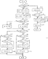
제1실시예에 있어서, 프런트엔진 리어드라이브구조를 가진 차량의 종동륜으로 되어 있는 좌우측전륜의 가속을 검출하고, 각 차륜의 가속도가 단위시간에 소정의 임계값 α이상으로 진동하는 주파수를 소정의 주파수 β와 비교한다. 좌우측차륜에 대한 주파수중 적어도 하나가 소정의 주파수 β보다 클경우, 차량은 악로를 주행하고 있는 것으로 판정된다. 미끄럼방지제어가 실행되지 않는 경우보다 미끄럼방지제어가 실행되는 경우에 임계값 α가 크게 설정된다. 예를들면, 미끄럼방지제어가 실행되는지의 여부를 ABS로부터 제어신호를 받는 미끄럼방지제어검출수단에 의하여 검출한다. 제1의 실시예에서의 악로를 차량이 주행하고 있는지의 여부를 검출하는 방법을, 제6도 및 제7도에 도시된 플로우챠아트를 참조하면서, 아래에 상세히 기술한다.In the first embodiment, the acceleration of the left and right front wheels, which are driven wheels of a vehicle having a front engine rear drive structure, is detected, and the frequency at which the acceleration of each wheel vibrates above a predetermined threshold α in a unit time is determined by a predetermined frequency. Compare with frequency β. When at least one of the frequencies for the left and right wheels is larger than the predetermined frequency β, the vehicle is determined to be traveling on the track. The threshold value α is set larger when the slip control is executed than when the slip control is not performed. For example, it is detected by the anti-skid control detecting means which receives a control signal from the ABS whether or not the anti-slip control is executed. A method of detecting whether or not the vehicle is traveling in a bad track in the first embodiment will be described in detail below with reference to the flowchart art shown in FIGS. 6 and 7.
스텝 S101에서, 타이머의 카운트치 T를 소정의 값 Test보다 작지 않은지, 즉 소정시간(예를들면, 0.7초)이 경과했는지의 여부를 판단한다. 전자가 후자보다 작은 값으로 판정될때에, 스텝 S102에서 좌측전륜 선행속도 WFLn에서 좌측전륜의 현재속도 WFLn-1을 감산하므로서 좌측전륜의 가속도 DWFL를 구할 수 있다.In step S101, it is determined whether the count value T of the timer is not smaller than the predetermined value Test, i.e., a predetermined time (for example, 0.7 seconds) has elapsed. When the former is determined to be smaller than the latter, the acceleration DWFL of the left front wheel can be obtained by subtracting the present front speed WFLn-1 of the left front wheel from the left front wheel front speed WFLn in step S102.
즉, DWFL=WFLn-WFLn-1That is, DWFL = WFLn-WFLn-1
스텝 S103에서 DWFL=DWFL-(WFLn-WFLn-4)/4의 공식에 따라서 좌측전륜의 가속도 DWFL을 오프셋보정한다. 이 오프셋보정은 차륜의 실제가속도를 얻기 위한 것이다. 스텝 S102에서 계산한 좌측전륜의 가속도 DWFL는 차체의 가속도를 포함하고 있다. 따라서 스텝 S102에서 계산환 좌측전륜의 가속도 SWFL에서 차체의 가속도를 감산하므로서 좌측전륜의 실제가속도 DWFL을 구할 수 있다. 차체는, 차륜의 회전을 시작하는 시간보다 늦게 움직이기 시작한다. 시간지연은 약 56msec이고 이 흐름(14mesc/cycle)의 4배와 동일하다. 따라서, 상기 공식에서 차륜의 4개 선행가속도의 평군치(WFLn-WFLn-4)/4를 차체의 가속도로 채택하고 있다.In step S103, the acceleration DWFL of the left front wheel is offset-corrected according to the formula of DWFL = DWFL- (WFLn-WFLn-4) / 4. This offset correction is to obtain the actual acceleration of the wheel. The acceleration DWFL of the left front wheel calculated in step S102 contains the acceleration of the vehicle body. Therefore, in step S102, the actual acceleration DWFL of the left front wheel can be obtained by subtracting the acceleration of the vehicle body from the acceleration SWFL of the left front wheel of the transfer ring. The body starts to move later than the time at which the wheel starts to rotate. The time delay is about 56msec and is equal to four times this flow (14mesc / cycle). Therefore, in the above formula, the four groups of the preceding acceleration of the wheel (WFLn-WFLn-4) / 4 is adopted as the acceleration of the vehicle body.
좌측전륜의 실제가속도 DWFL를 이렇게 구한 다음, 미끄럼방지제어가 실행되는지의 여부를 판정하고, 미끄럼방지제어가 실행되는 것이 판정될 경우 임계값 α가 0.70G로 설정되거나 0.5G로 설정된다(스텝 S104 내지 스텝 S106)좌측선륜의 실제가속도 DWFL가 스텝 S106 또는 스텝 S105에서 설정된 임계값 α 이상으로 진동하는 주파수(PCFL)를 계산한다. 즉, 좌측전륜의 실제가속도(DWFL)의 진동(시간에 따라 변경)이 제4도에 도시한 바와같을 경우, 진동의 피크치가 +α 또는 -α를 초과하는 주파수를 카운트하고, 제3도에 도시한 바와같은 경우에는, 피크치가 +α 및 -α를 교대 로 초과할 경유에만 카운트치가 증가된다. 즉, 피크치가 +α를 초과한 다음, 다음 피크치가 +α를 다시 초과할 경우이거나, 피크치가 -α를 초과한 다음 다음피크치가 다시 -α를 초과할 경우에는, 카운트치는 하나씩 증가된다, 이것은 좌측전륜의 실제가속도DWFL가 악로에 기인하여 진동할때에 피크치가 교대로 +α 및 -α를 초과하여야하기 때문이다. 이와같은 방법으로 주파수 PFCL을 카운트하므로서 차량이 악로를 주행하고 있는지를 정밀하게 판정할 수 있다.After the actual acceleration DWFL of the left front wheel is obtained in this way, it is determined whether or not slip control is executed, and when it is determined that slip control is executed, the threshold value α is set to 0.70G or 0.5G (step S104). Step S106) The frequency PCFL at which the actual acceleration DWFL of the left wheel rings vibrates above the threshold? Set in Step S106 or Step S105 is calculated. That is, when the vibration (change over time) of the actual acceleration (DWFL) of the left front wheel is shown in FIG. 4, the frequency at which the peak value of the vibration exceeds + α or -α is counted. In the case as shown, the count value is increased only when the peak value alternately exceeds + α and -α. That is, if the peak value exceeds + α and then the next peak value exceeds + α again, or if the peak value exceeds -α and the next peak value again exceeds -α, the count is increased by one, which is This is because the peak value should alternately exceed + α and -α when the actual acceleration DWFL of the left front wheel vibrates due to a bad road. By counting the frequency PFCL in this manner, it is possible to precisely determine whether the vehicle is driving in a bad lane.
즉, 스텝 S107에서 좌측전륜의 실제가속도 DWFL가 '0'보다 작지 않은지의 여부를 판정한다. 좌측전륜의 실제가속도 DWFL가 '0'보다 작다고 판정될 경우에는 스텝 S108에서 좌측전륜의 실제가속도 DWFL가 +α보다 큰지의 여부를 판정한다. 이 질문에 대한 대답이 'NO'일 경우 흐름이 종료되고 그렇지 않을 경우 스텝 S109에서 피크플래그 PFFL를 '1'인지의 여부를 판정한다. 피크플래그 PFFL이 '1', 즉 피크플래그 PFFL를 세트했다는 것은, 좌측전륜의 실제가속도 DWFL이 상기 흐름에서 -α를 초과하여 주파수카운트 PCFL이 한개 증분되었음을 의미한다. 한편, 피크플래그 PFFL이 '0'즉 피크플래그 PFFL이 리세트되었다는 것은, 좌측전륜의 실제가속도 DWFL이 선행흐름에서 +α를 초과하고 주파수의 카운트 PCFL이 한개 증분되었음을 의미한다. 따라서, 스텝 S109에서 피크플래그 PFFL이 '1'이 증분되었을 경우에는 주파수카운트 PCFL이 스텝 S110에서 한개의 증분된 다음 피크플래그 PFFL이 스텝 S111에서 '0'으로 리세트되어 종료된다. 그렇지 않으면, 하나의 피크차가 두배로 카운트되지 않도록 그리고 상술한 목적을 위하여 스텝S111 다음에서 흐름이 종료된다.That is, it is determined in step S107 whether the actual acceleration DWFL of the left front wheel is not less than "0". If it is determined that the actual acceleration DWFL of the left front wheel is smaller than "0", it is determined in step S108 whether the actual acceleration DWFL of the left front wheel is larger than + alpha. If the answer to this question is 'NO', the flow ends, and if not, it is determined in step S109 whether the peak flag PFFL is '1'. Setting the peak flag PFFL to '1', i.e., the peak flag PFFL, means that the actual acceleration DWFL of the front left wheel was incremented by one frequency count PCFL above -α in the flow. On the other hand, the peak flag PFFL is set to '0', that is, the peak flag PFFL is reset, which means that the actual acceleration DWFL of the left front wheel exceeds + α in the preceding flow and the count PCFL of the frequency is incremented by one. Therefore, when the peak flag PFFL is incremented by '1' in step S109, the frequency count PCFL is incremented by one in step S110, and then the peak flag PFFL is reset to '0' in step S111 and ends. Otherwise, the flow ends after step S111 so that one peak difference is not counted twice and for the purpose described above.
스텝 S107에서 좌측전륜의 실제가속도 DWFL이 '0'보다 작은지의 여부를 판정할 경우 스텝 S112에서 좌측전륜의 실제가속도 DWFL이 -α보다 작은지의 여부를 판정한다. 이 질문에 대한 대답이 'NO'일 경우 흐름은 종료하고 그렇지 않으면 피크플래그 PFFL이 '0'인지 여부를 스텝 S113에서 판정한다. 스텝 S113에서 피크플래그 PFFL이 '0'으로 판정될 경우, 주파수의 카운트 PCFL을 스텝 S114에서 한개 증분한 다음, 피크플래그 PFFL이 스텝 S115에서 '1'로 설정되고 흐름은 종료된다. 그렇지 않으면, 하나의 피크치를 두배로 카운트하지 않도록 그리고 상술한 목적을 위하여 스텝 S115를 완료한 후에 종료된다.When it is determined in step S107 whether the actual acceleration DWFL of the left front wheel is smaller than "0", it is determined in step S112 whether the actual acceleration DWFL of the left front wheel is smaller than -α. If the answer to this question is 'NO', the flow ends, otherwise it is determined in step S113 whether the peak flag PFFL is '0'. If the peak flag PFFL is determined to be '0' in step S113, the count PCFL of the frequency is incremented by one in step S114, then the peak flag PFFL is set to '1' in step S115 and the flow ends. Otherwise, the process ends after completing step S115 so as not to count one peak value twice and for the purpose described above.
소정의 시간이 경과할때까지 스텝 S101 내지 스텝 S115는 반복되고, 소정의 시간이 경과했을때 스텝 S116에서 타이머가 리세트된 후에 주파수 PCFL이 소정의 주파수 β(예를들면 β=10)보다 큰지의 여부를 스텝 S117에서 판정한다. 소정의 주파수 β보다 주파수 PCFL이 크지 않은 것으로 판정할 경우 좌측전면 악로플래그(AKPRFL)를 '0'으로 설정하고, 스텝 S119에서 주파수 PCFL을 '0'으로 설정한 다음 흐름이 종료된다. 좌측전면 악로플래그 AKRFL는 그것이 이 '1'인때에는, 좌측전륜이 악로를 주행하고 있는 것을 표시하고, 또한 그것이 '0'일때에는 좌측 전륜이 악로를 주행하고 있지 않는 것을 표시한다. 스텝 S117에서 주파수 PCFL이 소정의 주파수 β보다 큰것으로 판정될 경우 좌측악로플래그(AKRFL)를 스텝 S120에서 '1'로 세트하고 스텝 S119에서 주파수 PCFL을 0으로 설정한 다음 흐름은 종료된다.Steps S101 to S115 are repeated until a predetermined time has elapsed, and after the timer is reset in step S116 when the predetermined time has elapsed, is the frequency PCFL greater than the predetermined frequency β (e.g. β = 10)? Is determined in step S117. If it is determined that the frequency PCFL is not greater than the predetermined frequency β, the left front bad flag AKPRFL is set to '0', the frequency PCFL is set to '0' in step S119, and then the flow ends. The left front evil flag AKRFL indicates that the left front wheel is driving the mound when it is '1', and when it is '0', the left front wheel is not driving the mound. If it is determined in step S117 that the frequency PCFL is larger than the predetermined frequency β, the left evil flag AKRFL is set to '1' in step S120 and the frequency PCFL is set to 0 in step S119, and then the flow ends.
제6도에 표시한 플로우챠아트에서는 좌측진륜이 악로를 주행하고 있는지의 여부를 판정하는 방법을 나타내지만, 우측전륜이 악로를 주행하고 있는지의 여부를 동일한 방법으로 판정한다. 우측차륜이 악로를 주행하고 있는 것으로 판정될때에 우측전면 악로플래그 AKRFL을 '1'로 세트하고, 우측전륜이 악로를 주행하고 있지 않는 것으로 판정될 때에는 '0'으로 세트한다.In the flowchart shown in Fig. 6, a method of determining whether the left advance wheel is traveling on the bad track is shown, but it is determined by the same method whether the right front wheel is driving on the bad track. The right front bad flag AKRFL is set to '1' when it is determined that the right wheel is driving the bad track, and is set to '0' when it is determined that the right front wheel is not driving bad track.
본 실시예에 있어서, 좌우측 전륜중에 적어도 하나가 악로를 주행하고 있다고 판정할때차량이 악로를 주행하고 있다고 판정하고 차량악로플래그(AKRF)를 제7도의 스텝 S121에서 세트한다.In the present embodiment, when it is determined that at least one of the left and right front wheels is driving the bad track, it is determined that the vehicle is driving the bad track and the vehicle bad flag AKRF is set in step S121 of FIG.
제1실시예에서는, 좌측전면악로플래그(AKRFL) 및 우측전면악로플래그(AKRFR)중에 적어도 하나가 '1'일때 차량이 악로를 주행하고 있다고 판정되지만, 좌측전면악로플래그(AKRFL) 및 우측전면악로플래그(AKRFR)가 모두 1일때만 차량이 악로를 주행하고 있는 것으로 판정할 수도 있다. 또한, 제1실시예에서 차량이 악로를 주행하고 있는지의 여부를 종동륜의 가속도에 의거하여 판정하지만, 제1실시예에서와 동일한 방법으로 구동륜의 가속도에 의거하여 판정할 수도 있다. 또는 제1실시예서와 같이 동일한 방법으로 4개의 차륜의 가속도에 의거하여 판정할 수도 있다.In the first embodiment, it is determined that the vehicle is driving a bad track when at least one of the left front bad track flag AKRFL and the right front bad track flag AKRFR is '1', but the left front bad track flag AKRFL and A vehicle may be determined to be driving only when the right front evil track flag (AKRFR) is all 1s. Further, in the first embodiment, it is determined based on the acceleration of the driven wheel whether or not the vehicle is traveling on the track, but it can also be determined based on the acceleration of the drive wheel in the same manner as in the first embodiment. Alternatively, the determination may be made based on the acceleration of the four wheels in the same manner as in the first embodiment.
또한, 제1실시예애서는 임계값 α를, 미끄럼방지제어가 실행되고 있는지의 여부에 따라서 변경하지만, 브레이크페달이 눌려져 있는지의 여부에 따라서 또는 제동제어를 트랙션제어에서 실행하고 있는지의 여부에 따라서 임계값 α를 변경할 수도 있다.In the first embodiment, the threshold value α is changed depending on whether or not slip control is being executed, but depending on whether the brake pedal is depressed or whether brake control is being executed in traction control. It is also possible to change the threshold α.
또한, 제1실시예에서는 임계값 α를 미끄럼방지제어가 실행되는지의 여부에 따라서 임계값 α의 변경여부릍 결정하지만, 임계값 α를 다른 계수에 따라서 단계적으로 또는 연속적으로 변경할 수도 있다. 플러스쪽 진동에 대한 임계값 α의 절대값과 마이너스쪽 진동에 대한 임계값 α의 절대값은 서로 다를 수 있다. 플러스쪽 진동에 대한 임계값 α의 절대값과 마이너스쪽 진동에 대한 임계값 α의 절대값은, 미끄럼방지 제어가 실행될 경우, 서로 다른 양으로 증가할 수 있다. 또는 플러스쪽 진동에 대한 임계값 α의 절대값과 마이너스쪽 진동에 대한 임계값 α의 절대값중에 하나만, 미끄럼 방지제어가 실행될 경우, 증가시킬 수 있다.In the first embodiment, the threshold α is determined whether or not the threshold α is changed depending on whether or not the slip control is executed. However, the threshold α may be changed stepwise or continuously in accordance with other coefficients. The absolute value of the threshold α for the positive side vibration and the absolute value of the threshold α for the negative side vibration may be different. The absolute value of the threshold value α for the positive side vibration and the absolute value of the threshold value α for the negative side vibration can be increased by different amounts when the slip control is executed. Alternatively, only one of the absolute value of the threshold value α for the positive side vibration and the absolute value of the threshold value α for the negative side vibration can be increased when the anti-slip control is executed.
제1실시예의 악로검출장치에 있어서, 차량의 악로를 주행하고 있는지의 여부는, 미끄럼방지제어에 기인하는 차륜가속도의 진동변화에 영향을 받는 일이 없이 정확하게 판정될 수 있다.In the bad track detection apparatus of the first embodiment, whether or not the vehicle is traveling on the bad track can be accurately determined without being influenced by the vibration change of the wheel acceleration due to the slip control.
악로검출장치의 제2실싱를 제8도 및 제9도를 참조하면서 아래 설명한다. 제2의 실시예에 있어서, 프런트엔진 리어드라이브차량의 4개 차륜에 대한 차륜가속도를 검출하고, 미끄럼방지제어가 실행되지 않을 경우, 차량의 악로를 주행하고 있는지의 여부를, 좌우측전륜, 즉 종동륜의 가속도에 의기허여, 미끄럼방지제어가 실행되는지의 여부에 따라서 임계값 α가 변경되지 않는 것을 제외하고는 제1의 실시예와 동일한 방법으로 판정하고, 미끄럼방지제어가 실행될 경우, 좌우측후륜, 즉 구동륜의 가속도에 의거하여 미끄럼방지제어가 실행되는지의 여부에 따라서 임계값 α가 변경되지 않는 것을 제외하고는 제1의 실시예와 동일한 방법으로 판정한다.The second seal of the defect detection apparatus will be described below with reference to FIGS. 8 and 9. In the second embodiment, the wheel acceleration for the four wheels of the front engine rear drive vehicle is detected, and when the anti-skid control is not executed, whether the vehicle is traveling in the track of the vehicle, the left and right front wheels, i.e., Based on the acceleration of the driving wheel, the determination is made in the same manner as in the first embodiment except that the threshold value α is not changed in accordance with whether or not the slip control is executed. When the slip control is executed, the left and right rear wheels, That is, the determination is made in the same manner as in the first embodiment except that the threshold value α is not changed in accordance with whether or not the slip control is executed based on the acceleration of the drive wheel.
즉, 제2의 실시예에서, 좌측전면 악로플래그(AKRFL)을, 제8도의 플로우챠아트에 도시된 방법으로 좌측전륜이 악로를 주행하는 것으로 판정될 경우에는 '1'로 설정하고, 제8도의 플로우챠아트에 도시된 방법으로 좌측전륜이 악로를 주행하고 있지 않는 것으로 판정될 경우에는 '0'으로 설정한다. 제8도에 도시된 플로우챠아트에서는, 미끄럼 방지제어가 실행되는지의 여부에 따라서 임계값 α가 변경되지 않는 것을 제외하고는 제6도에 도시된 플로우챠아트와 실질적으로 동일하다. 따라서 여기서 기술하는 것을 생략한다. 동일한 방법으로 좌측전면악로플래그(AKRFL), 좌측후면악로플래그(AKRRL)및 우측악로플래그(AKRRR)를, 우측전륜, 좌측후륜, 및 우측후륜이 악로를 주행하고 있을때에 '1'로 설정하고, 우측전륜, 좌측후륜 및 우측후륜이 악로를 주행하고 있지 않는 것으로 판정될 경우에는 '0'으로 설정한다.That is, in the second embodiment, the left front evil flag AKRFL is set to '1' when it is determined that the left front wheel travels the bad track by the method shown in the flowchart of FIG. When it is determined that the left front wheel is not traveling in a bad lane by the method shown in the flowchart of Fig., It is set to '0'. In the flowchart art shown in FIG. 8, it is substantially the same as the flowchart art shown in FIG. 6 except that the threshold value α is not changed depending on whether or not slip control is executed. Therefore, the description is omitted here. In the same way, the left front evil track flag (AKRFL), the left rear bad track flag (AKRRL) and the right bad track flag (AKRRR) are set to '1' when the right front wheel, left rear wheel, and right rear wheel are driving the track. If it is determined that the right front wheel, the left rear wheel and the right rear wheel are not traveling in a bad lane, it is set to '0'.
제2실시예에 있어서, 차량이 악로를 주행하고 있는지의 여부가 제9도에 도시한 플로우챠아트에 의해 도시된 방법으로 판정된다.In the second embodiment, whether or not the vehicle is traveling on the track is determined by the method shown by the flowchart art shown in FIG.
즉, 미끄럼방지제어가 행해지고 있지 않을 경우, 좌전륜 악로플래그(AKRFL) 및 우전륜 악로플래그(AKRFR)중 적어도 하나가 1이면, 차량이 악로를 주행하고 있는 것으로 판정되고 차량악로플래그(AKRF)가 세트된다.(스텝 S139 및 S140). 한편, 미끄럼방지제어가 행해지고 있는 경우, 좌후륜 악로플래그(AKRRL) 및 우후륜악로플래그(AKRRR)가 모두 1이면, 차랑이 악로를 주행하고 있는 것으로 판정되고, 차량악로플래그(AKRF)가 세트된다(스텝 S139 내지 S141).That is, when the anti-slip control is not performed, if at least one of the left front wheel bad flag (AKRFL) and the right front bad wheel flag (AKRFR) is 1, it is determined that the vehicle is driving the bad track and the vehicle bad flag (AKRF) Are set (steps S139 and S140). On the other hand, when the anti-slip control is being performed, if both the left rear wheel bad track flag AKRRL and the right rear wheel bad track flag AKRRR are all 1, it is determined that the vehicle is driving the bad track, and the vehicle bad track flag AKRF is determined. It is set (steps S139 to S141).
제2실시예에 있어서, 미끄럼방지제어가 행해지고 있는 경우에는 좌후륜악로플래그(AKRRL) 및 우후륜악로플래그(AKRRR)가 모두 1일 경우에만 차량이 악로를 주행하는 것으로 판정되고 있지만, 좌후륜악로(AKRRL) 및 우후륜악로(AKRRR)중 적어도 하나가 1일때 차량이 악로를 주행하는 것으로 판정될 수도 있다.In the second embodiment, when the anti-slip control is being performed, it is determined that the vehicle runs the bad track only when the left rear wheel bad track flag AKRRL and the right rear wheel bad track flag AKRRR are both 1, When at least one of the rear wheel drive track AKRRL and the rear wheel drive track AKRRR is 1, the vehicle may be determined to drive the track.
또, 미끄럼방지제어가 행해질때 후륜(구동륜)의 차륜가속도에 의거하여 판정이 행해지는한 미끄럼방지제어가 행해지고 있지 않을 경우 전륜의 차륜가속도 또는 후륜의 차륜가속도중 어느 하나에 의거하여 차량이 악로를 주행하고 있는 것으로 판정될 수도 있다.If the anti-slip control is not performed as long as the determination is made based on the wheel acceleration of the rear wheel (drive wheel) when the anti-slip control is performed, the vehicle may be driven in accordance with either the wheel acceleration of the front wheel or the wheel acceleration of the rear wheel. It may be determined that the vehicle is traveling.
제2실시예에 있어서, 미끄럼방지제어가 행하지고 있을 경우, 차량이 악로를 주행하고 있는지의 여부는, 전륜에 가해지는 것보다 더작은 제동력이 가해지는 후륜의 차륜가속도에 의거하여 판정되며, 그들 가속도는 제동력에 있어서의 변동에 의한 영향을 덜받으며, 또한 차량이 악로를 주행하고 있는지의 여부가 미끄럼방지제어에 의한 차륜가속도의 진동변화의 영향을 적게 받아서 정확하게 판정될 수 있다.In the second embodiment, when the anti-skid control is being performed, whether the vehicle is traveling on the bad track or not is determined based on the wheel acceleration of the rear wheel to which a braking force is applied which is smaller than that applied to the front wheel. Acceleration is less affected by fluctuations in braking force, and whether or not the vehicle is traveling in a bad track can be accurately determined by being less affected by vibration change of wheel acceleration by anti-slip control.
악로검출장치의 제3실시예를 제10도를 참조해서 이하 설명한다.A third embodiment of the fault detection apparatus will be described below with reference to FIG.
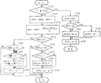
제3실시예에 있어서, 스프링상수를 그보다 더 큰값 및 더 적은 값중에서 선택할 수 있는 서스펜션장치가 갖춰진 프런트엔진리어드라이브차량의 종동륜인 좌 및 우전륜의 가속도가 검출되고, 각 차륜의 가속도가 단위시간당 소정의 임계값 α이상으로 진동하는 주파수가 소정의 주파수 β와 비교된다. 좌, 우전륜에 대한 주파수중 적어도 하나가 소정의 주파수 β보다 클경우, 차량은 악로를 주행하고 있는 것으로 판정된다. 소정의 주파수β는, 과, 후륜의 서스펜션의 스프링상수가 크면 더 크게 설정된다.In the third embodiment, the acceleration of the left and right front wheels, which are the driven wheels of the front engine rear drive vehicle equipped with the suspension device, from which the spring constant can be selected between a larger value and a smaller value, is detected, and the acceleration of each wheel is measured in units. The frequency oscillating above the predetermined threshold α per hour is compared with the predetermined frequency β. When at least one of the frequencies for the left and right front wheels is larger than the predetermined frequency β, the vehicle is determined to be traveling on the track. The predetermined frequency β is set larger when the spring constant of the suspension of the rear wheel is large.
즉, 제10도에 도시한 바와같이, 좌전류의 실제가속도 DWFL이 임계값 α이상으로 진동하는 주파수PCFL은 제2실시예(스텝 S142 내지 S153)에서와 똑같은 방법으로 카운트되며(스텝 S142 내지 S153), 반면에 소정의 주파수 β는, 좌 및 우전륜 서스펜션의 스프링상수가 크지 안않면 β1으로 세트되고, 스프링상수가 클 경우에는 β2로 세트되며, β2는 β1보다 더크다(스텝 S155 내지 S157). 좌 및 우전륜 서스펜션의스프링상수는 스프링상수를 검출하는 수단에 의해, 예를들면 스프링상수를 변화시키는 스위치로부터의 신호를 통해 검출된다. 그후, 주파수 PCFL이 스텝 S156 내지 스텝 157에서 세트된 소정의 주파수 β보다 더 큰지의 여부를 스텝 S158에서 판정한다. 주파수 PCFL이 소정의 주파수 β보다 더 크지 않다고 판정되면, 좌전륜악로플래그(AKRFL)는 스텝 S159에서 0으로 세트되고 플루오챠아트의 흐름은 스텝 S161에서 주파수 PCFL이 0으로 세트된 후에 종료된다. 스텝 S158에서 주파수 PCFL이 소정의 주파수 β보다 더큰 것으로 판정되면, 좌전륜악로플래그(AKRFL)는 1로 세트되고, 풀로우챠아트의 흐름은 주파수 PCFL이 스텝 S161에서 0으로 세트된 후에 종료된다.That is, as shown in FIG. 10, the frequency PCFL in which the actual acceleration DWFL of the left current oscillates above the threshold α is counted in the same manner as in the second embodiment (steps S142 to S153) (steps S142 to S153). On the other hand, the predetermined frequency β is set to β1 if the spring constants of the left and right front wheel suspensions are not large, and set to β2 if the spring constant is large, and β2 is larger than β1 (steps S155 to S157). . The spring constants of the left and right front wheel suspensions are detected by means of detecting the spring constant, for example via a signal from a switch that changes the spring constant. Then, it is determined in step S158 whether the frequency PCFL is larger than the predetermined frequency β set in steps S156 to 157. If it is determined that the frequency PCFL is not greater than the predetermined frequency β, the left front wheel evil flag AKRFL is set to zero in step S159 and the flow of fluorocharat ends after the frequency PCFL is set to zero in step S161. If it is determined in step S158 that the frequency PCFL is greater than the predetermined frequency β, the left front wheel drive flag AKRFL is set to 1, and the flow of the pull up art is finished after the frequency PCFL is set to 0 in step S161. .
우전륜이 악로를 주행하고 있는지의 여부는, 똑같은 방법으로 판정되며, 우륜이 악로를 주행하고 있다고 판정되면 우전륜악로플래그(AKRFR)는 1로 세트되고, 우전륜이 악로를 주행하고 있지 않다고 판정될 경우에는 0으로 세트된다.It is determined in the same way whether the right wheel is driving a bad track, and if it is determined that the right wheel is driving bad track, the right wheel bad track flag (AKRFR) is set to 1 and the right wheel is not driving bad track. If it is determined, it is set to zero.
본 실시예에 있어서, 좌 및 우전륜중 적어도 하나가 악로를 주행하고 있는 것으로 판정되면, 차량은 제1실시예에서와 똑같은 방법으로 악로를 주행하고 있는 것으로 판정된다.In the present embodiment, when it is determined that at least one of the left and right front wheels is traveling on the track, the vehicle is determined to be traveling on the track in the same manner as in the first embodiment.
제3실시예에 있어서, 서스펜션의 스프링상수는 2단계로 변화될 수 있으므로, 소정의 주파수β가 2단계로 변화되지만, 스프링상수가 2단계이상 또는 연속적으로 변화될 수 있으면 소정의 주파수β도 2단계이상 또는 연속적으로 변화될 수 있다. 또, 스프링상수검출수단은 스프링상수를 직접 검출할 수도 있다.In the third embodiment, the spring constant of the suspension can be changed in two stages, so that the predetermined frequency β is changed in two stages, but if the spring constant can be changed in two or more stages or continuously, the predetermined frequency β is also two degrees. It can be changed in steps or continuously. In addition, the spring constant detection means may directly detect the spring constant.
제3실시예에 있어서, 소정의 주파수β는 서스펜션의 스프링상수에 따라 변화되며, 차량이 악로를 주행하고 있는지의 여부는 서스펜션의 스프링상수의 변화에 의한 차륜가속도의 진동의 변화에 의한 영향을 받지않고 정확하게 검출될 수 있다.In the third embodiment, the predetermined frequency β is changed according to the spring constant of the suspension, and whether the vehicle is traveling on the track is not affected by the change in the vibration of the wheel acceleration due to the change of the spring constant of the suspension. Can be detected accurately.
악로검출장치의 제4실시예를 제11도를 참조하여 이하 설명한다.A fourth embodiment of the fault detection apparatus will be described below with reference to FIG.
제4실시예에 있어서, 감쇠력이 더 큰값 및 더 작은 값으로부터 선택될 수 있는 서스펜션장치가 갖춰진 프런트엔진리어드라이브 차량의 종동륜인 좌 및 우전륜의 차륜가속도가 검출되고, 단위시간당 소정의 임계값α 이상으로 진동하는 각 차륜의 가속도 주파수는 소정의 주파수β와 비교된다. 좌 및 우전륜에 대한 주파수중 적어도 하나의 소정의 주파수β보다 크면, 차량은 악로를 주행하고 있다고 판정된다. 임계값α는 좌 및 후륜 서스펜션의 감쇠력이 크면 적게 설정된다.In the fourth embodiment, wheel accelerations of the left and right front wheels, which are driven wheels of a front engine rear drive vehicle equipped with a suspension device, in which the damping force can be selected from a larger value and a smaller value, are detected, and a predetermined threshold value per unit time is detected. The acceleration frequency of each wheel vibrating above α is compared with a predetermined frequency β. If at least one of the frequencies for the left and right front wheels is greater than the predetermined frequency β, it is determined that the vehicle is traveling on the road. The threshold value α is set less if the damping force of the left and rear wheel suspensions is large.
본 실시예에 있어서, 미끄럼방지제어가 행해지고 있는지의 여부에 따라 임계값α를 변경시키는 대신에 임계값α가 전륜서스펜션의 감쇠력이 크면 α1으로 설정되고 크지 않으면(α2)로 설정된다는 것(제11도에 표시한 바와 같이 α2는 α1보다 크다)(스텝 S165 내지 S167)을 제외하고는 제1실시예에서와 똑같은 방법으로 좌전륜이 악로를 주행하고 있는지의 여부가 판정된다.In the present embodiment, instead of changing the threshold value α depending on whether or not anti-slip control is being performed, the threshold value α is set to α1 if the damping force of the front wheel suspension is large and not to large (α2) (11th). As shown in the figure, except that α2 is larger than α1 (steps S165 to S167), it is determined whether or not the left front wheel is traveling on the road in the same manner as in the first embodiment.
우전륜이 악로를 주행하고 있는지의 여부는 똑같은 방법으로 판정된다.It is determined in the same manner whether or not the right wheel is traveling on the track.
본 실시예에 있어서, 좌 및 우전륜중 적어도 하나가 악로를 주행하고 있다고 판정되면, 차량은 제1실시예에서와 똑같은 방법으로 악로를 주행하고 있다고 판정된다.In the present embodiment, when it is determined that at least one of the left and right front wheels is traveling on the track, it is determined that the vehicle is traveling on the track in the same manner as in the first embodiment.
그러나, 제4실시예에 있어서, 감쇠력은 2단계로 변화될 수 있으므로, 임계값α도 2단계로 변화되지만, 감쇠력이 2단계이상 또는 연속적으로 변화될 수 있으면 임계값α는 2단계이상 또는 연속적으로 변화될 수 있다. 또, 감쇠력검출수단은 직접 서스펜션의 감쇠력을 검출할 수 있다.However, in the fourth embodiment, since the damping force can be changed in two stages, the threshold α is also changed in two stages, but if the damping force can be changed in two or more stages or continuously, the threshold α is two or more stages or continuous. Can be changed to In addition, the damping force detection means can directly detect the damping force of the suspension.
제4실시예에 있어서, 임계값α는 서스펜션의 감쇠력에 따라 변화되기 때문에 차량이 악로를 주행하고 있는지의 여부가 서스펜션의 감쇠력의 변화에 의한 차륜가속도의 진동의 변화에 의한 영향을 받지 않고 정확하게 판정될 수 있다.In the fourth embodiment, since the threshold α is changed in accordance with the damping force of the suspension, whether or not the vehicle is traveling badly is accurately determined without being influenced by the change in the vibration of the wheel due to the change of the damping force of the suspension. Can be.
본 발명의 제3실시예에 의한 슬립제어장치를 제12도 내지 제15도를 참조하여 이하 설명한다.A slip control apparatus according to a third embodiment of the present invention will be described below with reference to FIGS.
제3실시예의 기계적인 구성은 제1실시예에서의 슬립제어유닛, 즉 트랙션제어유닛 UTR의 작동이 제1실시예의 것과 다르다는 것을 제외하고는 제1실시예의 것과 동일하다.The mechanical configuration of the third embodiment is the same as that of the first embodiment except that the operation of the slip control unit, that is, the traction control unit UTR in the first embodiment is different from that of the first embodiment.
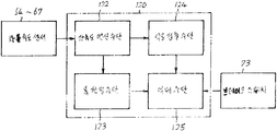
본 실시예에 있어서, 슬립제어유닛(UTR)은 트랙션제어 및 미끄럼방지제어를 행하는 슬립제어수단(100)과, 전륜이 악로를 주행하고 있는지의 여부를 검출하는 좌륜악로검출수단(200)과, 우륜이 악로를 주행하고 있는지의 여부를 검출하는 우륜악로검출수단(300)과, 좌륜 및 우륜악로검출수단중 적어도 하나가 차륜이 악로를 주행하고 있다는 것을 검출하면 차량이 악로를 주행하고 있다고 판정하는 제1판정수단(400)과, 좌륜 및 우륜악로검출수단이 모두 차륜이 악로를 주행하고 있다는 것을 검출하면 차량이 악로를 주행하고 있다고 판정하는 제2판정수단(500)과, 차량의 주행상태에 따라 제1 및 제2판정수단중 어느 하나를 선택하거나 슬립제어수단에 의해 행해지는 슬립제어의 종류를 선택해서, 선택된 판정수단이 차량이 악로를 주행하고 있다고 판정하면 슬립제어수단에 의해 행해지는 슬립제어의 내용을 변화시키는 악로보정수단(600)을 구비한다.In this embodiment, the slip control unit UTR includes slip control means 100 which performs traction control and anti-slip control, and left wheel evil detection means 200 which detects whether or not the front wheel is traveling on the track. If the at least one of the right wheel bad road detecting means 300 for detecting whether the right wheel is driving the bad track and the left wheel and right wheel bad track detecting means detects that the wheel is driving the bad road, the vehicle runs the bad track. The first judging means 400 for determining that the vehicle is running, and the second judging means 500 for judging that the vehicle is driving the bad road when both the left wheel and the right wheel bad road detecting means detect that the wheel is driving the bad road, and the vehicle If one of the first and second determination means is selected according to the driving state of the vehicle, or the type of slip control performed by the slip control means is selected, and the selected determination means determines that the vehicle is driving in the bad lane, Akro provided with a correction means (600) for changing the contents of the slip control is performed by the lip control means.
슬립제어수단(100)의 트랙션제어를 행하면, 악로보정수단(600)은 제13도에 도시한 바와같이 가속기페달의 답입량에 따라 제1판정수단(400) 또는 제2판정수단(500)을 선택한다.When the traction control of the slip control means 100 is performed, the evil correction means 600 uses the first determination means 400 or the second determination means 500 according to the depression amount of the accelerator pedal as shown in FIG. Choose.
제13도에 있어서, 가속기페달의 답입량 TH가 소정의 값 TH1(e.g., 50%)보다 작지 않은지의 여부를 판정한다(스텝 R1). 전자가 후자보다 작지 않다고 판정되면, 좌륜 및/또는 우륜이 악로를 주행하고 있는지의 여부가 스텝 R2에서 판정된다. 이 판정은 제2판정수단(500)에 의해 이루어진다. 좌륜 및/또는 우륜이 악로를 주행하고 있다고 판정되면, 슬립제어수단(100)은 제1임계슬립률 SET(제1목표슬립률)를 정상치SET1로 설정하고 제1임계슬림률 SET의 값 SET1에 의거하여 트랙션제어를 행한다(스텝 R3 및 R4). 그렇지 않으면, 악로보정수단(600)이 악로보정을 행한다. 즉, 제1임계슬립률 SET를 정상치 SET1보다 큰 보정값 SET2으로 설정하고(스텝 R5), 슬립제어수단은 제1임계슬립률 SET의 값 SET2에 의거하여 트랙션제어를 행한다(스텝 R6).In Fig. 13, it is determined whether the depression amount TH of the accelerator pedal is not smaller than the predetermined value TH1 (e.g., 50%) (step R1). If it is determined that the former is not smaller than the latter, it is determined in step R2 whether the left wheel and / or the right wheel are traveling on the bad track. This determination is made by the second determination means 500. If it is determined that the left wheel and / or the right wheel are traveling in the bad lane, the slip control means 100 sets the first threshold slip rate SET (first target slip rate) to the normal value SET1 and the value SET1 of the first threshold slim rate SET. On the basis of the above, traction control is performed (steps R3 and R4). Otherwise, the evil correction means 600 performs the evil correction. That is, the first critical slip rate SET is set to a correction value SET2 larger than the normal value SET1 (step R5), and the slip control means performs traction control based on the value SET2 of the first critical slip rate SET (step R6).
한편, 가속기페달의 답입량 TH이 소정의 값 TH1보다 적다는 것이 스텝 R1에서 판정되면, 제1판정수단(400)은 좌 및 우륜이 모두 악로를 주행하고 있는지의 여부를 스텝 R7에서 판정한다. 좌 및 우륜중 적어도 하나가 악로를 주행하고 있지 않다고 판정되면, 슬립제어수단(100)은 제1임계슬립률 SET(제1목표슬립률)을 정상치 SET1로 세트해서 제1임계슬립률 SET의 값 SET1에 의거하여 트랙션제어를 행한다(스텝 R8 및 R9). 그렇지 않으면 악로보정수만(600)이 악로보정을 행한다. 즉, 제1임계슬립률 SET를 정상치 SET1보다 큰 보정값 SET2으로 설정하고(스텝 R10), 슬립제어수단은 제1임계슬립률 SET(스텝 R11)의 보정값 SET2에 의거하여 트랙션 제어를 행한다.On the other hand, when it is determined in step R1 that the depression amount TH of the accelerator pedal is smaller than the predetermined value TH1, the first determination means 400 determines in step R7 whether both the left and the right wheels are traveling in the bad lane. If it is determined that at least one of the left and right wheels is not driving in a bad lane, the slip control means 100 sets the first threshold slip rate SET (first target slip rate) to the normal value SET1 to set the value of the first threshold slip rate SET. Traction control is performed based on SET1 (steps R8 and R9). Otherwise, only the
각 차륜이 악로를 주행하고 있는지의 여부는 제8도에서 설명한 것과 같은 방법으로 판정될 수 있다.Whether each of the wheels is traveling on the track can be determined in the same manner as described in FIG.
본 실시예에 있어서, 가속기페달의 답입량이 적으면 악로보정은 좌 및 우륜이 모두 악로를 주행하고 있을때에만 행해지고, 가속기페달의 답입량이 크면 악로보정은 좌 및 우륜중 하나만이 악로를 주행하고 있더라도 행해진다.In the present embodiment, if the depression amount of the accelerator pedal is small, the course correction is performed only when both the left and right wheels are driving the bad track, and if the depression amount of the accelerator pedal is large, only the one of the left and right wheels is driving the bad track. Even if it is done.
상술한 바와같이, 트랙션제어시의 악로보정은 가속성능을 향상시킨다. 가속기페달의 답입량이 적다는 것은 운전자가 큰 가속성능을 원하지 않는다는 것을 의미하며, 따라서 좌 및 우륜이 모두 악로를 수행하고 있을 때에만 악로보정을 행한다.As described above, the fault correction during traction control improves the acceleration performance. The small depression of the accelerator pedal means that the driver does not want a great acceleration performance, and therefore the aerodrome correction is performed only when both the left and right wheels are performing a bad track.
슬립제어수단(100)이 미끄럼방지제어를 행하면, 악로보정수단(600)은 제14도에 도시한 바와같이 제1판정수단(400)을 선택한다.When the slip control means 100 performs anti-slip control, the evil correction means 600 selects the first determination means 400 as shown in FIG.
즉, 좌 및 우륜이 모두 악로를 주행하고 있는지의 여부에 대한 판정여부가 스텝 Q1에서 판정된다. 좌 및 우륜이 모두 악로를 주행하고 있지 않다고 판정되면, 즉 제1판정수단(400)이 차량이 악로를 주행하고 있다고 판정하지 않을 경우, 슬립제어수단(100)은 제1임계슬립률 SET(제1목표슬립률)을 정상치 SET1로 설정하고 제1임계슬립률 SET의 값 SET1에 의거하여 미끄럼방지제어를 행한다(스텝 Q2 및 Q3). 그렇지 않으면, 악로보정수단(600)이 악로보정을 행한다. 즉, 제1임계슬립률 SET를 정상치 SET1보다 큰 보정값 SET2으로 설정하고(스텝 R10), 슬립제어수단은 제1임계슬립률 SET의 보정값 SET2에 의거하여 트랙션제어를 행한다(스텝 R11).In other words, it is determined at step Q1 whether the left and right wheels are traveling on the road. If it is determined that both the left and the right wheels are not traveling in a bad lane, that is, when the first judging means 400 does not determine that the vehicle is traveling in bad lanes, the slip control means 100 sets the first threshold slip rate SET (first). 1 target slip rate) is set to the normal value SET1, and slip control is performed based on the value SET1 of the first critical slip rate SET (steps Q2 and Q3). Otherwise, the evil correction means 600 performs the evil correction. That is, the first critical slip rate SET is set to the correction value SET2 larger than the normal value SET1 (step R10), and the slip control means performs traction control based on the correction value SET2 of the first critical slip rate SET (step R11).
악로보정이 미끄럼방지 제어중에 행해지면, 차륜이 록되기 쉬워진다. 따라서 악로보정이 좌 및 우륜중 하나만이 악로를 주행하고 있을때 행해지면, 악로를 주행하고 있지 않는 다른 차륜도 록되기 쉬워져서 그 차륜의 제동효율이 저하되며 그에 의해 차량의 제동효율이 저하한다. 따라서, 미끄럼방지 제어중에는, 좌 및 우륜중 하나만이 악로를 주행하고 있으면 악로보정은 행하지 않는 것이 바람직스럽다.If the defect correction is performed during the anti-slip control, the wheels are likely to lock. Therefore, when the badway correction is performed when only one of the left and right wheels is driving the bad lane, other wheels not driving the bad lane are more likely to be locked, and the braking efficiency of the wheel is lowered, thereby lowering the braking efficiency of the vehicle. Therefore, during anti-slip control, it is preferable that no bad track correction is performed if only one of the left and right wheels is driving the bad track.
슬립제어수단(100)이 트랙션제어 및 미끄럼방지제어 모두를 행하면, 악로보정수단(600)은 제15도에 도시한 방법으로 제1판정수단(400) 또는 제2판정수단을 선택한다.When the slip control means 100 performs both traction control and anti-slip control, the evil correction means 600 selects the first judging means 400 or the second judging means in the manner shown in FIG.
제15도에 있어서, 미끄럼방지제어가 행해지고 있는지의 여부가 스텝 P1에서 판정되고, 미끄럼방지제어가 행해지고 있다고 판정되면, 좌 및 우전륜 모두 악로를 주행하고 있을 경우 악로보정이 행해진다. 그렇지 않으면, 요우레이트 Y가 소정값 Y1보다 작지 않은지의 여부(스텝 P3), 정상트랙션제어모우드가 선택되었는지의 여부(스텝 P4)그리고 가속기페달의 답입량이 50%보다 작지 않은지의 여부(스텝 P5)가 판정된다. 요우레이트가 소정값 Y1보다 작다고 판정되면, 정상트랙션제어모우드는 선택되지 않은 것이며(스포오트(sport)모우드가 선택됨), 동시에 가속기페달의 답입량은 50%보다 적으며, 좌 및 우후륜중 적어도 하나가 악로를 주행하고 있다고 판정되면 차량은 악로를 주행하고 있다고 판정되고 트랙션 제어중에 악로보정이 행해진다(스텝 P6). 요우레이트 Y가 소정값 Y1보다 작지 않다고 판정되고, 정상트랙션제어모우드가 선택되었다고 판정되고, 동시에 가속기페달의 답입량이 50%보다 작지 않다고 판정되며, 좌 및 우후륜중의 적어도 하나가 악로를 주행하고 있다고 판정될 경우 차량은 악로를 주행하고 있다고 판정되어, 트랙션제어시에 악로보정이 행해진다(스텝 P6).In FIG. 15, if it is determined in step P1 whether anti-slip control is being performed and if it is determined that anti-slip control is being performed, the evil correction is performed when both the left and right front wheels are driving the bad track. Otherwise, whether or not the yaw rate Y is not smaller than the predetermined value Y1 (step P3), whether the normal traction control mode is selected (step P4), and whether the depression amount of the accelerator pedal is not less than 50% (step P5). ) Is determined. If it is determined that the yaw rate is smaller than the predetermined value Y1, the normal traction control mode is not selected (the sport mode is selected), and at the same time, the amount of depression of the accelerator pedal is less than 50%, and at least of the left and right wheels. If it is determined that one is traveling in a bad lane, the vehicle is determined to be traveling in bad lanes, and bad track correction is performed during traction control (step P6). It is determined that the yaw rate Y is not smaller than the predetermined value Y1, the normal traction control mode is selected, and at the same time, it is determined that the depression amount of the accelerator pedal is not less than 50%, and at least one of the left and the rear wheels drives the evil road. If it is determined that the vehicle is running, it is determined that the vehicle is traveling on the track, and the track correction is performed at the time of traction control (step P6).
요우레이트 Y가 소정값 Y1보다 작지 않다는 것이 판정되거나, 정상트랙션제어모우드가 선택되었다고 판정되거나, 가속기페달의 답입량이 50%보다 작지 않다고 판정되면, 좌 및 우후륜이 모두 악로를 주행하고 있다고 판정될 경우에 차량이 악로를 주행하고 있다고 판정되어 트랙션제어시에 악로보정이 행해진다(스텝 P6).If it is determined that the yaw rate Y is not smaller than the predetermined value Y1, it is determined that the normal traction control mode is selected, or it is determined that the depression amount of the accelerator pedal is not less than 50%, it is determined that both the left and right rear wheels are driving in the lane. In this case, it is determined that the vehicle is traveling on the track, and the track correction is performed during traction control (step P6).
본 발명의 제4실시예를 제16도 내지 제18도를 참조하여 이하 설명한다.A fourth embodiment of the present invention will be described below with reference to FIGS. 16-18.
제4실시예의 기계적인 구성은 제1실시예의 슬립제어유닛, 즉 트랙션제어유닛(UTR)의 작동이 제1실시예의 것과 다르다는 것을 제외하고는 제1실시예와 대체로 동일하다.The mechanical configuration of the fourth embodiment is generally the same as that of the first embodiment except that the operation of the slip control unit, that is, the traction control unit UTR of the first embodiment is different from that of the first embodiment.
본 실시예에 있어서는, 슬립제어유닛은 미끄럼장지제어부(120) 및 트랙선제어부(121)를 형성한다.In the present embodiment, the slip control unit forms the
제16도에 도시한 바와같이, 미끄럼방지제어부(120)는 차륜속도센서(64)∼(67)에 의해 검출된 각 차륜의 회전속도에 의거해서 차륜(IFL), (IFR), (IRL) 및 (IRR)의 가속도 또는 감속도를 계산하는 차륜가속도연산수단(122)과, 각 차륜의 차륜가속도를 소정의 기준값과 비교하여 차륜이 록되기 쉬운지의 여부를 판정하고, 밸브(36A), (36B), (37A) 및 (37B)를 제어해서 록되기 쉽다고 판정된 차륜에 가해진 브레이크유압을 감소시키는 록판정수단(123)을 포함한다.As shown in FIG. 16, the
미끄럼방지제어부(120)는 또한 차량이 악로를 주행하고 있다고 검출하는 악로검출수단(124)과, 만일 브레이크스위치(73)가 브레이크페달(25)이 눌려져 있다는 것을 표시하지 않으면 악로검출수단(124)이 차량이 악로를 주행하고 있다고 검출할 경우, 악로검출수단(124)의 출력신호 및 브레이크스위치(73)(제1도)의 출력신호를 받아서 미끄럼방지제어부(120)가 미끄럼방지제어를 개시하는 것을 금지하는 금지수단을 구비한다.The
제17도에 도시한 바와같이, 트랙션제어부(121)은 좌우전륜(IFL)와 (IFR)의 회전속도의 평균치를 계산하는 평균차속 연산수단(126)과, 전륜회전속도의 평균치로부터 후륜의 회전속도를 감산해서 각후륜(IRL) 및 (IRR)(구동륜)의 슬립을 계산하는 슬립연산수단(127)과, 각후륜의 슬립을 소정의 기준치와 비교하고 전자가 후자보다 더클때, 차륜이 슬립하고 있다고 판정하는 슬립판정수단(128)으로 구성된다. 트랙션제어부(121)은, 후륜이 슬립하고 있다고 슬립판정수단(128)이 판정할때, 상기한 방식으로 엔진출력제어와 브레이크제어를 행한다.As shown in FIG. 17, the
이하 제18도에 도시한 플로우차아트를 참조하여 미끄럼방지제어부(120)의 동작을 설명한다. 스텝 S221에서 차륜센서의 출력신호에 의거하여 계산된 각 차륜의 감속도(WG)와 공지의 수단(도시하지 않음)에 의해 검출된 차체의 감속도 G가 판독된다. 스텝 S222에서, 차체의 감속도 G를 차륜의 감속도 WG로부터 감산하여 차륜의 실제감속도 WG-G를 얻고, 차륜의 실제감속도가 소정의 기준감속도 r보다 더큰지, 즉 차륜의감속도가 큰지와 차륜이 록하는 경향이 있는지를 판정한다.Hereinafter, the operation of the
전자가 후자보다 더크다고 판정될때에, 스텝 S223에서 악로검출수단(124)이 차량이 악로를 주행하고 있다고 판정했는지의 여부가 판정된다. 차량이 악로를 주행하고 있지 않다고 판정될때, 미끄럼방지제어를 행하는 제어신호는 스텝 S225에서 밸브(36A), (36B), (37A) 및 (37B)로 출력된다.When it is determined that the former is larger than the latter, it is determined in step S223 whether the evil detection means 124 has determined that the vehicle is driving the evil course. When it is determined that the vehicle is not traveling on the road, control signals for performing anti-slip control are output to the
한편, 스텝 S223에서 그것이 판정될때 스텝 S224에서는 브레이크스위치(73)가 온, 즉 브레이크페달이 눌려져 있는지의 여부가 판정된다. 브레이크스위치(73)가 온이라고 판정될때, 미끄럼방지제어를 행하는 제어신호는 스텝 S225에서 밸브(36A), (36B), (37A) 및 (37B)에 출력된다. 그러나 스텝 S224에서 브레이크스위치(73)가 온이 아니라고 판정되었을때 제어신호는 출력되지 않는다.On the other hand, when it is determined in step S223, it is determined in step S224 whether the
상기에서 알수 있는 바와같이, 본 실시예의 장치에서, 미끄럼방지 제어부는 차륜의 감속도가 차륜이 록되는 경향에 있다는 것을 나타낼 경우에도 브레이크페달이 눌려져 있지 않으면, 차량이 악로를 주행하고 있을때 미끄럼방지제어부(120)가 미끄럼방지제어를 개시하지 못하게 금지하는 금지수단(125)을 구비한다. 차량이 악로를 주행하고 있을때, 차륜감속도는 노면상의 요철로 인하여 변동하고, 변동하는 동안 차륜의 감속도는 브레이크가 적용되지 않았을지라도 차륜이 록되는 경향이 있다고 검출하도록 미끄럼방지제어부를 잘못 인도할 수 있다. 특히 차량이 미끄럼방지제어장치와 트랙션제어장치 모두를 구비하고 트랙션제어장치가, 악로를 주행하고 있는 동안 구동륜에 제동을 가할때, 구동륜은 갑자기 감속되고, 미끄럼방지제어장치는 구동륜이 록하려고 한다는 것을 잘못 판단할 수 있으므로 트랙션제어는 중단되고 미끄럼방지제어는 개시된다. 제4실시예에서 금지수단(125)이 그와 같은 미끄럼방지 제어장치의 오작동을 방지한다.As can be seen from the above, in the device of the present embodiment, the anti-slip control unit is provided with an anti-slip control unit when the vehicle is driving in an evil track, unless the brake pedal is pressed even when the deceleration of the wheel indicates that the wheel tends to be locked. Prohibition means 125 for prohibiting 120 from starting the anti-slip control. When the vehicle is driving in a bad lane, the wheel deceleration fluctuates due to unevenness on the road, and during the fluctuation, the deceleration of the wheel incorrectly misleads the anti-skid control unit to detect that the wheel tends to lock even if the brake is not applied. Can be. In particular, when the vehicle is equipped with both an anti-skid control device and a traction control device and the traction control device brakes the drive wheels while driving in a bad lane, the drive wheels are suddenly decelerated, and the anti-skid control device tries to lock the drive wheels. Since the erroneous judgment can be made, the traction control is stopped and the slip control is started. In the fourth embodiment, the prohibiting means 125 prevents the malfunction of such an anti-slip control device.
Claims (22)
Applications Claiming Priority (8)
| Application Number | Priority Date | Filing Date | Title |
|---|---|---|---|
| JP2-72642 | 1990-03-22 | ||
| JP7264290A JP2818900B2 (en) | 1990-03-22 | 1990-03-22 | Bad road judgment device |
| JP2-80275 | 1990-03-28 | ||
| JP8027590A JP2856828B2 (en) | 1990-03-28 | 1990-03-28 | Braking force control device |
| JP2-83608 | 1990-03-30 | ||
| JP2-83609 | 1990-03-30 | ||
| JP8360890A JP2818902B2 (en) | 1990-03-30 | 1990-03-30 | Vehicle travel control device |
| JP2083609A JP2917039B2 (en) | 1990-03-30 | 1990-03-30 | Vehicle slip control device |
Publications (2)
| Publication Number | Publication Date |
|---|---|
| KR910016537A KR910016537A (en) | 1991-11-05 |
| KR950002933B1 true KR950002933B1 (en) | 1995-03-28 |
Family
ID=27465493
Family Applications (1)
| Application Number | Title | Priority Date | Filing Date |
|---|---|---|---|
| KR1019910004549A KR950002933B1 (en) | 1990-03-22 | 1991-03-22 | Slip control system for vehicle and rough road detecting system |
Country Status (4)
| Country | Link |
|---|---|
| US (1) | US5117934A (en) |
| EP (2) | EP0449118B1 (en) |
| KR (1) | KR950002933B1 (en) |
| DE (2) | DE69112247T2 (en) |
Cited By (1)
| Publication number | Priority date | Publication date | Assignee | Title |
|---|---|---|---|---|
| KR100896922B1 (en) * | 2007-12-11 | 2009-05-11 | 현대자동차주식회사 | Method for controlling drive power of vehicle |
Families Citing this family (65)
| Publication number | Priority date | Publication date | Assignee | Title |
|---|---|---|---|---|
| JP2965627B2 (en) * | 1990-06-22 | 1999-10-18 | マツダ株式会社 | Vehicle Traction Control Device |
| JP2902055B2 (en) * | 1990-06-07 | 1999-06-07 | マツダ株式会社 | Vehicle traction control device |
| WO1993000507A1 (en) * | 1991-06-26 | 1993-01-07 | Nippondenso Co., Ltd. | Acceleration slip controller for vehicles |
| JP2616302B2 (en) * | 1991-09-25 | 1997-06-04 | 三菱電機株式会社 | Anti-skid control device |
| JP2946881B2 (en) * | 1991-11-11 | 1999-09-06 | トヨタ自動車株式会社 | Throttle valve control device for internal combustion engine |
| DE4200997C2 (en) * | 1992-01-16 | 1994-02-03 | Steyr Daimler Puch Ag | Method for determining the driving dynamics safety reserve of motor vehicles |
| GB9212098D0 (en) * | 1992-06-06 | 1992-07-22 | Lucas Ind Plc | Method of and apparatus for traction control |
| DE4222159A1 (en) * | 1992-07-06 | 1994-01-13 | Bosch Gmbh Robert | Traction control system |
| JPH06122332A (en) * | 1992-10-09 | 1994-05-06 | Nippondenso Co Ltd | Slip control device for vehicle |
| US5390120A (en) * | 1992-12-08 | 1995-02-14 | Eaton Corporation | Method and apparatus for determining a need for vehicle braking system maintenance |
| GB9318502D0 (en) * | 1993-09-07 | 1993-10-20 | Lucas Ind Plc | Apparatus for and method of resonance control in a brake intervention traction control system |
| JP3158848B2 (en) * | 1994-03-16 | 2001-04-23 | 日産自動車株式会社 | Traction control device for vehicles |
| TW325448B (en) * | 1994-08-29 | 1998-01-21 | Toyoda Chuo Kenkyusho Kk | Anti-lock brake controlling apparatus |
| US5627755A (en) * | 1994-09-09 | 1997-05-06 | Kelsey-Hayes Company | Method and system for detecting and compensating for rough roads in an anti-lock brake system |
| US5524080A (en) * | 1994-11-22 | 1996-06-04 | Zexel Torsen Inc. | Traction control with variable threshold |
| US5710704A (en) * | 1994-11-25 | 1998-01-20 | Itt Automotive Europe Gmbh | System for driving stability control during travel through a curve |
| DE19515059A1 (en) * | 1994-11-25 | 1996-05-30 | Teves Gmbh Alfred | Vehicle ride stability regulator with limited reference yaw rate |
| US5701248A (en) * | 1994-11-25 | 1997-12-23 | Itt Automotive Europe Gmbh | Process for controlling the driving stability with the king pin inclination difference as the controlled variable |
| US5732378A (en) * | 1994-11-25 | 1998-03-24 | Itt Automotive Europe Gmbh | Method for determining a wheel brake pressure |
| US5732379A (en) * | 1994-11-25 | 1998-03-24 | Itt Automotive Europe Gmbh | Brake system for a motor vehicle with yaw moment control |
| US5774821A (en) * | 1994-11-25 | 1998-06-30 | Itt Automotive Europe Gmbh | System for driving stability control |
| US5742507A (en) * | 1994-11-25 | 1998-04-21 | Itt Automotive Europe Gmbh | Driving stability control circuit with speed-dependent change of the vehicle model |
| US5710705A (en) * | 1994-11-25 | 1998-01-20 | Itt Automotive Europe Gmbh | Method for determining an additional yawing moment based on side slip angle velocity |
| US5732377A (en) * | 1994-11-25 | 1998-03-24 | Itt Automotive Europe Gmbh | Process for controlling driving stability with a yaw rate sensor equipped with two lateral acceleration meters |
| US5711024A (en) * | 1994-11-25 | 1998-01-20 | Itt Automotive Europe Gmbh | System for controlling yaw moment based on an estimated coefficient of friction |
| US5694321A (en) * | 1994-11-25 | 1997-12-02 | Itt Automotive Europe Gmbh | System for integrated driving stability control |
| US5671144A (en) * | 1995-05-01 | 1997-09-23 | Zexel Torsen Inc. | Combined power limiting and power distributing traction control system for improving vehicle performance in turns |
| JP3367277B2 (en) * | 1995-06-05 | 2003-01-14 | 株式会社豊田中央研究所 | Friction state detecting device and power steering device |
| JP3257351B2 (en) * | 1995-07-07 | 2002-02-18 | 三菱自動車工業株式会社 | Vehicle turning control device |
| JP3592444B2 (en) * | 1996-06-11 | 2004-11-24 | 株式会社ホンダエレシス | Anti-lock brake control device for vehicles |
| JPH1038067A (en) * | 1996-07-18 | 1998-02-13 | Toyota Motor Corp | Control device of vehicle |
| KR100267332B1 (en) * | 1996-12-27 | 2000-10-16 | 정몽규 | Braking Control Method on Rough Roads |
| DE19859506B4 (en) * | 1997-12-23 | 2005-07-28 | Aisin Seiki K.K., Kariya | Detection system for unpaved roads |
| DE19933389A1 (en) | 1998-07-29 | 2000-02-03 | Continental Teves Ag & Co Ohg | Method to identify bad stretch of road being driven on by vehicle and to control vehicle speed accordingly |
| DE19954282B4 (en) * | 1999-11-11 | 2011-08-18 | Robert Bosch GmbH, 70469 | Slip control system |
| US6952637B2 (en) | 2000-09-09 | 2005-10-04 | Kelsey-Hayes Company | Rough road detection using suspension system information |
| US6401853B1 (en) * | 2000-11-13 | 2002-06-11 | General Motors Corporation | Power-hop responsive engine torque control method |
| US6591178B2 (en) * | 2001-10-02 | 2003-07-08 | Delphi Technologies, Inc. | Vehicle traction control with rough road correction |
| JP2004090886A (en) * | 2002-09-04 | 2004-03-25 | Advics:Kk | Traction control device of vehicle |
| JP2004306695A (en) * | 2003-04-03 | 2004-11-04 | Haradakuni:Kk | Drive system switching device, its method and its program |
| JP4244182B2 (en) * | 2003-11-17 | 2009-03-25 | 本田技研工業株式会社 | Anti-lock brake control method |
| JP4371270B2 (en) * | 2005-03-31 | 2009-11-25 | 株式会社日立製作所 | Vehicle driving force device |
| US9121715B2 (en) * | 2005-04-14 | 2015-09-01 | General Motors Llc | Method for determining vehicle location including road surface data |
| FR2914993B1 (en) * | 2007-04-13 | 2009-05-22 | Renault Sas | METHOD AND DEVICE FOR DETECTING A POOR ROAD FOR A MOTOR VEHICLE. |
| EP2138366B1 (en) | 2008-06-26 | 2013-03-20 | Kawasaki Jukogyo Kabushiki Kaisha | Slip suppression control system for vehicle |
| EP2138365B1 (en) | 2008-06-26 | 2015-05-06 | Kawasaki Jukogyo Kabushiki Kaisha | Slip suppression control system for vehicle |
| EP2138368B1 (en) | 2008-06-26 | 2013-03-20 | Kawasaki Jukogyo Kabushiki Kaisha | Slip suppression control system for vehicle |
| EP2138367B1 (en) | 2008-06-26 | 2015-05-13 | Kawasaki Jukogyo Kabushiki Kaisha | Slip suppression control system for vehicle |
| JP4927919B2 (en) * | 2009-09-16 | 2012-05-09 | 日立オートモティブシステムズ株式会社 | Vehicle control device |
| JP5049325B2 (en) * | 2009-09-17 | 2012-10-17 | 日立オートモティブシステムズ株式会社 | Vehicle control device |
| US8405522B2 (en) | 2010-09-30 | 2013-03-26 | Ford Global Technologies, Llc | Lane departure haptic warning with compensation for road-caused vibration |
| US8561749B2 (en) | 2011-09-19 | 2013-10-22 | Hb Performance Systems, Inc. | ATV or UTV differential with integrated sensors |
| GB201210282D0 (en) | 2012-06-11 | 2012-07-25 | Jaguar Cars | Vehicle and method of control thereof |
| JP6213020B2 (en) | 2013-07-31 | 2017-10-18 | 株式会社アドヴィックス | Vehicle control device |
| DE102013014672A1 (en) * | 2013-09-04 | 2015-03-05 | Wabco Gmbh | Method for controlling an electronic brake system |
| AU2014402646B2 (en) * | 2014-07-31 | 2019-02-21 | Komatsu Ltd. | Work vehicle and control method for work vehicle |
| US9879621B2 (en) * | 2015-12-08 | 2018-01-30 | Ford Global Technologies, Llc | Fuel vapor flow based on road conditions |
| IT201600087202A1 (en) * | 2016-08-25 | 2018-02-25 | I E T S P A | METHOD AND APPARATUS OF AUTOMATIC ADJUSTMENT OF A VEHICLE IN A PERFORMANCE CONDITION OF PERFORMANCE |
| GB2565547B (en) * | 2017-08-14 | 2022-03-02 | Jaguar Land Rover Ltd | Estimating terrain roughness |
| FR3075155B1 (en) * | 2017-12-20 | 2020-10-23 | Jtekt Europe Sas | IMPROVEMENT OF THE FEELING OF A ROAD PROFILE BY VARIATION OF A GAIN ACCORDING TO VEHICLE SPEED AND FLYING TORQUE |
| US11358710B2 (en) | 2018-02-23 | 2022-06-14 | The Boeing Company | Methods and apparatus for controlling landing gear retract braking |
| US10933982B2 (en) * | 2018-02-26 | 2021-03-02 | The Boeing Company | Methods and apparatus for controlling landing gear retract braking |
| JP2022108414A (en) * | 2021-01-13 | 2022-07-26 | 本田技研工業株式会社 | Vehicle control device |
| US11859571B2 (en) * | 2021-07-21 | 2024-01-02 | Ford Global Technologies, Llc | Methods for a road surface metric |
| IT202100019283A1 (en) * | 2021-07-21 | 2023-01-21 | Alba Robot S R L | METHOD FOR CORRECTING ODOMETRY ERRORS DURING THE AUTONOMOUS HANDLING OF A WHEEL APPARATUS AND RELATIVE CONTROL UNIT |
Family Cites Families (16)
| Publication number | Priority date | Publication date | Assignee | Title |
|---|---|---|---|---|
| JPS60596A (en) * | 1983-06-16 | 1985-01-05 | 株式会社デンソー | Road surface state identifier |
| JPS6022548A (en) * | 1983-07-19 | 1985-02-05 | Nippon Denso Co Ltd | Antiskid control device |
| DE3535843A1 (en) * | 1985-10-08 | 1987-04-16 | Bosch Gmbh Robert | METHOD FOR CONTINUOUSLY DETERMINING THE FACTORY VALUE (MY) |
| JPH0615325B2 (en) * | 1985-10-11 | 1994-03-02 | 日産自動車株式会社 | Wheel spin detector |
| JPH0688532B2 (en) * | 1985-12-27 | 1994-11-09 | 曙ブレーキ工業株式会社 | Anti-skidding control method |
| EP0254943B1 (en) * | 1986-07-24 | 1993-03-10 | Mazda Motor Corporation | Vehicle slip control apparatus |
| JPS63141864A (en) * | 1986-12-02 | 1988-06-14 | Sumitomo Electric Ind Ltd | Wheel spin control device |
| DE3644139A1 (en) * | 1986-12-23 | 1988-07-07 | Daimler Benz Ag | METHOD FOR MONITORING FUNCTIONS OF AN ELECTROMECHANICAL REGULATION SYSTEM THAT PROVIDES THE GROUND LIFE OF WHEELS OF A MOTOR VEHICLE |
| JP2620310B2 (en) * | 1987-07-09 | 1997-06-11 | 住友電気工業株式会社 | Wheel behavior detector |
| JP2704623B2 (en) * | 1988-02-12 | 1998-01-26 | 曙ブレーキ工業株式会社 | Anti-lock control method |
| US4926333A (en) * | 1988-04-20 | 1990-05-15 | Mitsubishi Jidosha Kogyo Kabushiki Kaisha | Traction control apparatus |
| JPH0238174A (en) * | 1988-07-29 | 1990-02-07 | Aisin Seiki Co Ltd | Road surface condition sensor and vehicle level controller |
| JP2773774B2 (en) * | 1989-03-31 | 1998-07-09 | マツダ株式会社 | Automotive slip control device |
| US4947332A (en) * | 1989-09-27 | 1990-08-07 | General Motors Corporation | Road surface estimation |
| US4991103A (en) * | 1989-11-01 | 1991-02-05 | General Motors Corporation | Rear wheel anti-lock brake controller |
| JPH1029636A (en) | 1996-07-17 | 1998-02-03 | Dainippon Shigyo Kk | Pallet made of corrugated fiberboard |
-
1991
- 1991-03-21 DE DE69112247T patent/DE69112247T2/en not_active Expired - Fee Related
- 1991-03-21 EP EP91104447A patent/EP0449118B1/en not_active Expired - Lifetime
- 1991-03-21 EP EP95102262A patent/EP0655362B1/en not_active Expired - Lifetime
- 1991-03-21 DE DE69129502T patent/DE69129502T2/en not_active Expired - Fee Related
- 1991-03-22 KR KR1019910004549A patent/KR950002933B1/en not_active IP Right Cessation
- 1991-03-22 US US07/673,460 patent/US5117934A/en not_active Expired - Fee Related
Cited By (1)
| Publication number | Priority date | Publication date | Assignee | Title |
|---|---|---|---|---|
| KR100896922B1 (en) * | 2007-12-11 | 2009-05-11 | 현대자동차주식회사 | Method for controlling drive power of vehicle |
Also Published As
| Publication number | Publication date |
|---|---|
| EP0449118B1 (en) | 1995-08-23 |
| EP0655362A3 (en) | 1995-07-05 |
| DE69112247D1 (en) | 1995-09-28 |
| KR910016537A (en) | 1991-11-05 |
| EP0655362B1 (en) | 1998-05-27 |
| US5117934A (en) | 1992-06-02 |
| EP0449118A2 (en) | 1991-10-02 |
| DE69129502T2 (en) | 1998-09-17 |
| DE69112247T2 (en) | 1996-01-25 |
| DE69129502D1 (en) | 1998-07-02 |
| EP0655362A2 (en) | 1995-05-31 |
| EP0449118A3 (en) | 1992-05-27 |
Similar Documents
| Publication | Publication Date | Title |
|---|---|---|
| KR950002933B1 (en) | Slip control system for vehicle and rough road detecting system | |
| JP2964044B2 (en) | Vehicle traction control device | |
| JP2902055B2 (en) | Vehicle traction control device | |
| US5262952A (en) | Slip control system for motor vehicle | |
| US5379222A (en) | System for controlling the running state of a vehicle in accordance with a steering angle | |
| US5325300A (en) | Traction control system for motor vehicle | |
| US5636909A (en) | Traction control system for vehicle | |
| JP3393654B2 (en) | Vehicle slip control device | |
| JPH05633A (en) | Slip controller of vehicle | |
| US5481455A (en) | System for detecting hydroplaning of vehicle | |
| US5193888A (en) | Slip control system for motor vehicle | |
| JPH0585342A (en) | Slip control device for vehicle | |
| US7474951B1 (en) | Process for automatic drive slip control (ASR) | |
| JP3153556B2 (en) | Vehicle slip control device | |
| JP2917039B2 (en) | Vehicle slip control device | |
| JP2813918B2 (en) | Vehicle traction control device | |
| JP2818901B2 (en) | Vehicle slip control device | |
| JP3271776B2 (en) | Vehicle slip control device | |
| JP2818902B2 (en) | Vehicle travel control device | |
| JPH0478645A (en) | Bad road judging device for vehicle with antilock brake system | |
| JPH0585339A (en) | Road surface friction coefficient detecting device | |
| JPH04126636A (en) | Traction control device of vehicle | |
| JP2873490B2 (en) | Vehicle traction control device | |
| JP3059226B2 (en) | Vehicle brake control device | |
| JP2808159B2 (en) | Vehicle slip control device |
Legal Events
| Date | Code | Title | Description |
|---|---|---|---|
| A201 | Request for examination | ||
| E902 | Notification of reason for refusal | ||
| G160 | Decision to publish patent application | ||
| E701 | Decision to grant or registration of patent right | ||
| GRNT | Written decision to grant | ||
| FPAY | Annual fee payment |
Payment date: 20020320 Year of fee payment: 8 |
|
| LAPS | Lapse due to unpaid annual fee |