KR940000025B1 - Thermo-couple attaching apparatus - Google Patents
Thermo-couple attaching apparatus Download PDFInfo
- Publication number
- KR940000025B1 KR940000025B1 KR1019860011067A KR860011067A KR940000025B1 KR 940000025 B1 KR940000025 B1 KR 940000025B1 KR 1019860011067 A KR1019860011067 A KR 1019860011067A KR 860011067 A KR860011067 A KR 860011067A KR 940000025 B1 KR940000025 B1 KR 940000025B1
- Authority
- KR
- South Korea
- Prior art keywords
- thermocouple
- burner
- engagement
- burner cap
- locking member
- Prior art date
Links
Images


Classifications
-
- G—PHYSICS
- G01—MEASURING; TESTING
- G01K—MEASURING TEMPERATURE; MEASURING QUANTITY OF HEAT; THERMALLY-SENSITIVE ELEMENTS NOT OTHERWISE PROVIDED FOR
- G01K1/00—Details of thermometers not specially adapted for particular types of thermometer
- G01K1/14—Supports; Fastening devices; Arrangements for mounting thermometers in particular locations
Abstract
내용 없음.No content.
Description
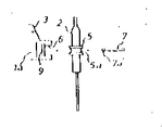
제1도는 본 발명에 의한 열전대의 부착장치의 1실시예를 도시한 정면도.1 is a front view showing one embodiment of a thermocouple attachment device according to the present invention.
제2도는 평면도.2 is a plan view.
제3도는 주요부의 분해 정면도.3 is an exploded front view of the main part.
제4도는 주요부의 분해 평면도.4 is an exploded plan view of the main part.
제5도는 계지부재를 달리한 정면도.5 is a front view with different locking members.
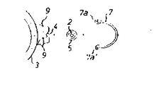
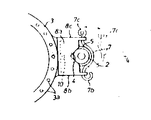
제6도는 다른 실시예의 일부 절결 정면도.6 is a partially cutaway front view of another embodiment.
제7도는 평면도.7 is a plan view.
제8도는 주요부의 분해 정면도.8 is an exploded front view of the main part.
제9도는 종래예의 정면도이다.9 is a front view of a conventional example.
* 도면의 주요부분에 대한 부호의 설명* Explanation of symbols for main parts of the drawings
1 : 버어너본체 2 : 열전대1: burner body 2: thermocouple
3 : 버어너캡 4 : 계합오목부3: burner cap 4: engagement recess
5 : 계합단부 6 : 끼워맞춤부5: engagement end 6: fitting portion
7 : 계지부재7: locking member
본 발명은 테이블 풍로 그밖의 각종 가스기구의 타다말고 꺼지는 안전용 열전대의 부착장치에 관한 것이다.The present invention relates to a device for attaching a safety thermocouple that is burned out of a table furnace and other various gas appliances.
종래 이 종류의 열전대의 부착에는 예를들면 제9도에 도시한 바와같은 버어너본체(1')의 한측에 튀어나오게 설치한 볼록부(8')의 부착구멍(9')에 열전대(2')를 관통 삽입하여 이것을 멈춤나사(10')에 의해 고정하는 수단을 채택하고 있는 것이 일반적이다.Conventionally, this type of thermocouple is attached to the attachment hole 9 'of the convex portion 8' which protrudes on one side of the burner body 1 'as shown in FIG. It is common to adopt means for inserting through ') and fixing it by the set screw 10'.
그러나 상기 종래의 부착수단으로는 열전대(2')의 부착에 있어서, 특히 버어너본체(1')의 버어너캡(3')과 열전대(2')와 상하방향의 관계칫수(H')를 눈칫수로 정하고 있으므로, 이 관계칫수(H')가 일정하지 않고, 그 부착정확도에 획일성이 없기 때문에 화력을 줄인 경우에 열전대(2')의 출력이 지나치게 저하하여 가스기구가 작동을 정지하는 등의 오작동을 야기하는 일이 있다는 결점이 있고, 또 열전대(2')의 고장, 버어너의 청소등으로 열전대(2')를 버어너본체(1')로부터 떼어내는 경우나 버어너 자신을 떼어내는 경우에 멈춤나사(10')가 열이나 끓인 국물등으로 녹이슬고, 또한 열전대 자신도 부착구멍(9')에 늘어붙어나기 때문에 그 떼어내는 것이 극히 곤란하였다.However, in the conventional attachment means, in the attachment of the thermocouple 2 ', in particular, the burner cap 3' and the thermocouple 2 'of the burner body 1' and the relative dimension (H ') in the vertical direction Since the relation dimension (H ') is not constant and there is no uniformity in the attachment accuracy, the output of the thermocouple (2') is excessively reduced when the thermal power is reduced, and the gas mechanism stops operation. There is a drawback that there may be a malfunction, such as to cause a malfunction of the thermocouple (2 '), and the thermocouple (2') removed from the burner body (1 ') or burner itself due to a failure of the thermocouple (2'), cleaning of the burner, etc. When the screw was removed, the set screw 10 'was rusted by heat, boiled broth, and the like, and the thermocouple itself was attached to the attachment hole 9', which was extremely difficult to remove.
그래서 본 발명은 버어너캡과 열전대와 가로세로의 관계칫수를 획일적으로 하여 오작동을 방지하는데 가장 적합한 정확도를 항상 유지하며, 또한 열전대의 붙이고 떼기도 원터치로 용이하게 또한 확실하게 할 수 있도록 하여 상기 종래의 제결점을 해결하는 것을 목적으로 한 열전대의 부착장치를 제공하는 것이다.Therefore, the present invention always maintains the most accurate accuracy to prevent malfunction by uniformly maintaining the relationship between the burner cap and the thermocouple and the length and width, and also allows the attachment and detachment of the thermocouple easily and reliably with one touch. It is to provide a thermocouple attachment device for the purpose of solving the drawbacks.
본 발명은 버어너본체(1)의 한측에 열전대(2)의 측면부가 접하여 버어너캡(3)과 열전대(2)와의 가로방향의 관계칫수(S)를 정하는 계합오목부(4)와 열전대(2)의 계합단부(5)가 끼워맞춤이 되어 버어너캡(3)과 열전대(2)와의 상하방향의 관계칫수(H)를 정하는 끼워맞춤부(6)를 설치, 이 계합오목부(4)와 끼워맞춤부(6)로서 위치 결정된 열전대(2)를 계지부재(7)에서 떼고 붙이기 자유롭게 유지시킴에 의해 버어너캡(3)과 열전대(2)와의 가로세로의 관계칫수(S), (H)의 획일화와 열전대(2)의 붙이고 떼기의 원터치화를 도모한 것이다.According to the present invention, the side surface portion of the
[실시예]EXAMPLE
다음 본 발명에 의한 열전대의 부착장치의 실시예를 도면에 의거하여 설명한다.Next, an embodiment of an attachment device for a thermocouple according to the present invention will be described with reference to the drawings.
[제1실시예][First Embodiment]
제1도 내지 제5도에서 1은 버어너본체로, 버어너헤드(1a)와 혼합관(1b)으로 구성되고, 그의 버어너헤드(1a)에는 다수의 주불꽃구멍(主炎孔)(3a)과 보조불꽃구멍(3b)을 갖춘 버어너캡(3)이 붙이고 떼기가 자유롭게 끼워붙여져 있다. 2는 열전대로 환상오목홈(5a)을 가진 계합단부를 인체적으로 갖추고 있다. 4는 버어너본체(1)의 버어너헤드(1a)의 일측에 돌출설치한 볼록부(8)에 설치한 계합오목부로, 열전대(2)의 측면부가 접하여 버어너캡(3)과 열전대(2)와의 가로방향의 관계칫수(예를들면, 버어너캡(3)의 중심과 열전대(2)의 중심과의 사이)(S)를 결정하기 위한 것으로, 실시예에서는 V자 모양의 오목홈으로서 이 V자상 오목홈에 열전대(2)의 측면부가 죄우의 2점에서 접하며, 또한 후술하는 끼워맞춤부(6)의 존재에 의해 이것이 상하에서 접함으로써 버어너캡(3)에 대한 열전대(2)의 가로방향의 위치결정이 일정한 위치에 용이하게, 또한 확실하게 행할 수 있는 동시에 그 자세도 일정(대략 수직상태)하게 유지할 수 있도록 되어 있다.1 to 5, the burner body is composed of a burner head 1a and a mixing tube 1b, and the burner head 1a has a plurality of main flame holes ( The
6은 볼록부(8)에 뚫은 끼워맞춤부로, 상기 열전대(2)의 계합단부(5)가 끼워맞춤하여 버어너캡(3)과 열전대(2)와의 상하방향의 관계칫수(예를들면 버어너캡(3)의 상면과 열전대(2)의 상면과의 사이)(H)를 정하기 위한 것으로 볼록부(8)의 계합오목부(4)에 열전대(2)의 측면부가 접하면 이 끼워맞춤부(6)에 열전대(2)의 계합단부(5)가 끼워맞춤이 되도록 관계위치를 유지하여 설치되어 있다. 7은 상기 계합오목부(4)와 끼워맞춤부(6)에서 위치결정된 열전대(2)를 보호 지지하기 위한 계지부재로서 제1도 내지 제4도의 실시예에서는, 내열내식성의 탄성선재를 굴곡시켜 형성된 C자상 스프링에 의한 계지부재를 사용하여 볼록부(8)의 양측에 돌설한 계합 볼록돌기(9')(9)에 이 계지부재(7)의 끝부분의 계합부(7a)(7a')가 원활, 확실하게 걸거나 벗길 수 있도록 되어서 이 계지부재(7)에 의해 열전대(2)의 붙이고 떼기를 용이하게 행하도록 하고 있다.6 is a fitting portion drilled in the
이때 계합단부(5)의 환상오목홈(5a)에 계지부재(7)를 끼우면 그 위치결정이 용이하게 할 수 있으므로 붙이고 떼기 동작이 보다 확실하게 할 수 있으나 이 환상 오목홈(5a)을 설치하지 않아도 계지부재(7)에서는 열전대(2)가 바깥으로 탈락하는 것을 방지할 뿐이므로 하등 지장은 없다.At this time, if the
또 제5도의 변형예는 판상의 스프링을 굴곡하여 계지부재(7)를 형성한 것이므로, 그외는 앞서의 실시예와 동일하므로 그 설명은 생략한다.In addition, since the
[제2실시예]Second Embodiment
제6도 내지 제8도에 있어서, 제1실시예에서는 볼록부(8)를 버어너헤드(1a)의 일측에 일체로 형성하였으나, 본 실시예는 판금 그밖의 것으로 만든 별체(別體)의 상자형 볼록부(8)를 버어너헤드(1a)의 일측에 멈춤나사(10)에 의해 고정시킨 것으로, 이 상자형 볼록부(8)의 상하판(8a, 8a')에 열전대(2)의 측면부가 접하여 버어너캡(3)과 열전대(2)와의 가로방향의 관계칫수(S)를 결정하기 위한 V자형의 계합오목부(4)를 설치하는 동시에, 상자형 볼록부(8)의 상하판(8a, 8a') 사이에 열전대(2)에 일체 형성시키는 계합단부(5)가 끼워맞춤되어 버어너캡(3)과 열전대(2)와의 상하 방향의 관계칫수(H)가 결정되는 끼워맞춤부(6)를 설치하고 있다.6 to 8, in the first embodiment, the
또 계지부재(7)로서 내열내식성의 탄성선재를 굴곡한 압압레버를 사용하여, 그 일단(7b)을 볼록부(8)의 한쪽의 측판(8b)에 자유로이 끼우고 타단(7c)은 다른쪽의 측판(8c)에 설치한 "<" 자상의 계합홈(11)에 걸거나 벗김을 자유로이 하여 계합오목부(4)와 끼워맞춤부(6)에 의해 위치결정된 열전대(2)를 이 계지부재(7)의 타단(7c)을 계합홈(11)에 걸거나 벗김 하는 것만으로 붙이고 떼기를 자유롭게 보호 지지 가능토록 되어 있다. 그밖의 구조는 제1실시예와 동일하며, 동일부분에 동일부호를 부여하였으므로 그 설명은 생략한다.Moreover, using the press lever which bend | folded the heat-resistant corrosion-resistant elastic wire rod as the
그러나 버어너헤드(1a)의 일측에 설치한 볼록부(8)의 끼워맞춤부(6)에 열전대(2)의 계합단부(5)를 끼워맞춤하여 그의 측면부를 계합오목부(4)에 밀어대어, 그런후에 계지부재로 이것을 압압보호 지지시키면 버어너본체(1)에 대하여 열전대(2)의 부착을 할 수 있다. 이때 볼록부(8)의 계합오목부(4)에 열전대(2)의 측면부가 접하는 것으로 버어너캡(3)과 열전대(2)와의 가로방향의 관계칫수(S)가 결정되며, 또한 볼록부(8)의 끼워맞춤부(6)에 열전대(2)의 계합단부(5)가 끼워맞춤되므로 버어너캡(3)과 열전대(2)와의 상하방향의 관계칫수(H)가 결정되어, 또한 이 위치결정된 열전대(2)는 계지부재(7)에서 탈락하지 않도록 원터치로 강고하게 유지되는 것이다.However, the engagement ends 5 of the
다음에 열전대(2)를 떼어낼때에는 계지부재(7)를 계합홈(11)으로부터 벗기어서 계지부재(7)에 의한 보호유지를 풀면 열전대(2)는 버어너본체(1)로부터 간단, 용이하게 분리할 수 있다.Next, when removing the
본 발명은 이상 설명한 바와같이, 버어너캡(3)과 열전대(2)와의 가로세로의 관계칫수(S), (H)가 획일적으로 정하여지며 그리고 버어너본체(1)에 대한 열전대(2)를 붙이고 떼는 것이 계지부재(7)에 의해 간단, 용이하게 행할 수 있는 구조로 하였으므로, 열전대(2)의 설치위치가 타다말고 꺼지는 방지에도 가장 적합한 위치에 정확도가 좋게 항상 유지되기 때문에 그 타다말고 꺼지는 것은 없게 되고 안전성은 향상한다. 또 열전대(2)를 교환하는 경우든가, 버어너를 청소하는 경우에 열전대(2)를 떼어낼때에는 멈춤나사를 풀 필요가 없고 단지 계지부재(7)를 벗기어서 그 보호지지를 풀면 열전대(2)를 버어너본체(1)로부터 간단 용이하게 분리할 수 있는 것이다.As described above, the dimensions (S) and (H) of the vertical and horizontal relationship between the
Claims (1)
Applications Claiming Priority (3)
| Application Number | Priority Date | Filing Date | Title |
|---|---|---|---|
| JP1985198634U JPH0349408Y2 (en) | 1985-12-24 | 1985-12-24 | |
| JP???60-198634 | 1985-12-24 | ||
| JP198634 | 1987-08-07 |
Publications (2)
| Publication Number | Publication Date |
|---|---|
| KR870006403A KR870006403A (en) | 1987-07-11 |
| KR940000025B1 true KR940000025B1 (en) | 1994-01-05 |
Family
ID=16394463
Family Applications (1)
| Application Number | Title | Priority Date | Filing Date |
|---|---|---|---|
| KR1019860011067A KR940000025B1 (en) | 1985-12-24 | 1986-12-22 | Thermo-couple attaching apparatus |
Country Status (2)
| Country | Link |
|---|---|
| JP (1) | JPH0349408Y2 (en) |
| KR (1) | KR940000025B1 (en) |
Family Cites Families (3)
| Publication number | Priority date | Publication date | Assignee | Title |
|---|---|---|---|---|
| JPS5163155U (en) * | 1974-11-13 | 1976-05-18 | ||
| JPS5821754B2 (en) * | 1977-04-28 | 1983-05-02 | 星崎電機株式会社 | shaved ice vending machine |
| JPS5821754U (en) * | 1981-08-04 | 1983-02-10 | 株式会社日立ホームテック | Thermocouple holding device |
-
1985
- 1985-12-24 JP JP1985198634U patent/JPH0349408Y2/ja not_active Expired
-
1986
- 1986-12-22 KR KR1019860011067A patent/KR940000025B1/en not_active IP Right Cessation
Also Published As
| Publication number | Publication date |
|---|---|
| KR870006403A (en) | 1987-07-11 |
| JPH0349408Y2 (en) | 1991-10-22 |
| JPS62107470U (en) | 1987-07-09 |
Similar Documents
| Publication | Publication Date | Title |
|---|---|---|
| JP2007298248A (en) | Gas burner | |
| FI91795B (en) | Non-vertical scaffolding element with fastening device | |
| KR940000025B1 (en) | Thermo-couple attaching apparatus | |
| US5895597A (en) | Electric heater support and mounting assembly | |
| US6068314A (en) | Wire rack handling tool | |
| ES515198A0 (en) | PROCEDURE FOR OBTAINING COATINGS BASED ON POLYSOLIANATES ON HEAT RESISTANT SUBSTRATES. | |
| JPH0440655Y2 (en) | ||
| JPH0426170B2 (en) | ||
| JPH0512621Y2 (en) | ||
| KR900004979Y1 (en) | Attachment for using thermocouples for stove | |
| JPH0244553Y2 (en) | ||
| KR920001342Y1 (en) | Sticking structure of ignition member | |
| JPH0212451Y2 (en) | ||
| JPS6140265Y2 (en) | ||
| JPH0743621Y2 (en) | Thermocouple fitting | |
| JP3953345B2 (en) | Gas combustion equipment | |
| KR920000788Y1 (en) | Holding device for ignition pulg or themocouple | |
| KR880000019Y1 (en) | Gas apparatus for securiety | |
| JPH0516997Y2 (en) | ||
| JP2007146562A (en) | Grating fixture and grating | |
| JPH0313623Y2 (en) | ||
| SU1703274A2 (en) | Cutter with mechanical linkage of multiface non-remachinable plate | |
| JP3077511B2 (en) | Engagement structure of holder and base | |
| JPS6116330Y2 (en) | ||
| KR950006629Y1 (en) | Pilot burner of gas boiler |
Legal Events
| Date | Code | Title | Description |
|---|---|---|---|
| A201 | Request for examination | ||
| E902 | Notification of reason for refusal | ||
| G160 | Decision to publish patent application | ||
| E701 | Decision to grant or registration of patent right | ||
| GRNT | Written decision to grant | ||
| FPAY | Annual fee payment |
Payment date: 20051222 Year of fee payment: 13 |
|
| EXPY | Expiration of term |