KR930003986B1 - Water rate control device in hot water boiler - Google Patents
Water rate control device in hot water boiler Download PDFInfo
- Publication number
- KR930003986B1 KR930003986B1 KR1019880016574A KR880016574A KR930003986B1 KR 930003986 B1 KR930003986 B1 KR 930003986B1 KR 1019880016574 A KR1019880016574 A KR 1019880016574A KR 880016574 A KR880016574 A KR 880016574A KR 930003986 B1 KR930003986 B1 KR 930003986B1
- Authority
- KR
- South Korea
- Prior art keywords
- circuit
- temperature
- control valve
- heated
- output
- Prior art date
Links
Images


Classifications
-
- F—MECHANICAL ENGINEERING; LIGHTING; HEATING; WEAPONS; BLASTING
- F24—HEATING; RANGES; VENTILATING
- F24H—FLUID HEATERS, e.g. WATER OR AIR HEATERS, HAVING HEAT-GENERATING MEANS, e.g. HEAT PUMPS, IN GENERAL
- F24H9/00—Details
- F24H9/20—Arrangement or mounting of control or safety devices
- F24H9/2007—Arrangement or mounting of control or safety devices for water heaters
- F24H9/2035—Arrangement or mounting of control or safety devices for water heaters using fluid fuel
-
- F—MECHANICAL ENGINEERING; LIGHTING; HEATING; WEAPONS; BLASTING
- F28—HEAT EXCHANGE IN GENERAL
- F28F—DETAILS OF HEAT-EXCHANGE AND HEAT-TRANSFER APPARATUS, OF GENERAL APPLICATION
- F28F27/00—Control arrangements or safety devices specially adapted for heat-exchange or heat-transfer apparatus
- F28F27/02—Control arrangements or safety devices specially adapted for heat-exchange or heat-transfer apparatus for controlling the distribution of heat-exchange media between different channels
Abstract
내용 없음.No content.
Description
제1도는 본 발명의 원리 설명도.1 is an explanatory view of the principle of the present invention.
제2도는 제1실시예의 설명도.2 is an explanatory diagram of a first embodiment.
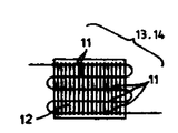
제3도는 피가열관군의 평면도.3 is a plan view of the heating tube group.
제4도는 제2실시예의 요부 설명도.4 is an explanatory diagram of main parts of the second embodiment.
제5도는 제3실시예의 설명도.5 is an explanatory diagram of a third embodiment.
제6도는 종래예의 설명도.6 is an explanatory diagram of a conventional example.
제7도는 선행예의 설명도.7 is an explanatory diagram of a preceding example.
* 도면의 주요부분에 대한 부호의 설명* Explanation of symbols for main parts of the drawings
1 : 피가열 회로 2 : 바이패스 회로1: heating circuit 2: bypass circuit
3 : 유량비율 조정밸브 10 : 관체3: flow rate ratio adjustment valve 10: pipe
11 : 피가열관 30 : 연산구동회로11: heating tube 30: operation driving circuit
31 : 제1비례 제어밸브 40 : 입수온 검지수단31: first proportional control valve 40: water temperature detection means
41 : 제1서미스터 61 : 제2서미스터41: first thermistor 61: second thermistor
62 : 제2비례 제어밸브 63 : 제2구동회로62: second proportional control valve 63: second drive circuit
64 : 출탕 온도 설정기64: tapping temperature setter
본 발명은 급탕기의 열교환기의 탕온 조절 장치에 관한 것으로서, 특히 열교환기내의 피가열관의 온도를 일정 온도 이상으로 유지함으로써 열교환기 내에서의 드레인(drain) 발생을 억제하는 것에 관한 것이다.BACKGROUND OF THE
종래기술의 문제점을 보면 종래의 급탕기의 열교환기에서는, 제6도와 같은 구성이 사용되어 왔으며, 열교환기의 관체(罐體)(10)을 끼운 피가열회로(1)과 관체(10)을 우회하는 바이패스 회로(2)을 조합, 채용하여 이들 양 회로의 합류점 이하의 하류쪽에 설치한 밸브로 부터 원하는 온도의 뜨거운 물을 얻게 된다.In view of the problems of the prior art, in the heat exchanger of the conventional hot water heater, the configuration as shown in FIG. 6 has been used, and bypasses the
이 종래의 것으로서는 입구에서의 물의 전량을 열교환기에 의하여 가열하는 경우에 비하여 피가열 회로(1)의 피가열관(11)을 지나는 물의 양이 적게되므로, 그만큼, 이 피가열관(11)의 온도가 높아져서, 드레인의 발생이 어렵게 된다.In this conventional method, the amount of water passing through the
그러나, 출탕량의 조절범위가 크고, 게다가 출탕온도의 조절범위가 큰 형식의 것에 있어서, 상기 종래의 것을 그대로 사용하는 것만으로는 피가열관에 드레인이 발생하는 것을 억제할 수 없다.However, in the form of a large adjustment range of the tapping amount and a large adjustment range of the tapping temperature, it is not possible to suppress the occurrence of a drain in the heating tube just by using the conventional one as it is.
이것은 급탕능력이 큰 형식의 열교환기에서는 피가열관(11)의 총 길이가 길어져서, 연소 배기류의 하류측에 위치한 부분의 피가열관 온도가 낮아지기 때문이다. 특히, 저온의 온수를 대량으로 얻으려 하는 경우, 이 경향이 두드러지게 되어, 피가열관(11)의 분위기 가스가 결로(結露)하여, 열교환기내에 흘러내리는 것이다.This is because the total length of the
이러한 결점을 해소하기 위한 것으로서, 제7도와 같이, 바이패스 회로(2)와 피가열회로(1)와의 합류점이나 분기점 또는 그 사이의 어느 회로에, 유량비율 조정밸브(3)을 삽입함과 아울러, 피가열회로(1)의 특정지역에 이 부분의 온도를 검지하는 검지수단(4)을 장착해서, 이 검지수단으로 부터의 출력에 의하여 상기 유량비율 조정밸브(3)을 작동하도록 한 것이 일본 실원소 61-95985호에서 제안 되었다.In order to solve such a fault, as shown in FIG. 7, the flow rate ratio adjustment valve 3 is inserted into the confluence point, the branch point of the
이 선행기술의 것으로서는, 검지수단(4)로부터의 제어신호에 의하여 피가열관(11)의 온도를 일정 온도 이상으로 설정할 수 있도록 드레인의 발생이 방지된다.In this prior art, the generation of drain is prevented so that the temperature of the
그러나, 이 선행기술에서는, 유량비율 조정밸브의 동작이 피가열회로(1)의 가열상태에 기인하는 출력상태에 의하여 제어되는, 소위 피드백제어(feed back control)이므로, 소정의 제어상태로 될때까지 일정의 시간을 요한다. 따라서, 이시간 동안 드레인의 발생을 방지할 수 없게 된다. 따라서 본 발명의 주된 목적은 피드 포워드 제어(feel forward control)에 의해 피가열관에서의 드레인 발생을 확실히 방지하는 것이다.However, in this prior art, since the operation of the flow rate ratio adjusting valve is so-called feedback control, which is controlled by the output state resulting from the heating state of the circuit to be heated 1, until it reaches a predetermined control state. It requires a certain amount of time. Therefore, it is impossible to prevent the generation of drain during this time. Therefore, the main object of the present invention is to reliably prevent the occurrence of drain in the tube to be heated by feel forward control.
즉 본 발명은 급탕기용 열교환기와, 피가열관을 구비하여 열교환기의 관체에 삽입되는 피가열 회로와; 관체를 우회하는 바이패스 회로와; 상기 피가열 회로와 상기 바이패스 회로의 합류점이나 분기점 또는 이들 사이의 어느회로에 설치되는 유량 비율 조정밸브를 구비하며, 상기 유량 비율 조정밸브는 이것의 구동회로로부터의 출력에 응하여 피가열관을 드레인이 발생하지 않을 정도의 온도로 유지하게끔 피가열 회로와 바이패스 회로의 유량비율을 제어하도록 된 급탕기의 탕온 조절 장치에 있어서, 피가열관에서의 드레인 발생을 확실히 방지하기 위해 피가열관의 온도를 피드 포워드 제어에 의하여 일정온도 이상으로 유지시키는 것을 기술적 과제로 한다.That is, the present invention includes a heat exchanger for a hot water heater and a heating circuit having a heated tube inserted into a tube of the heat exchanger; A bypass circuit for bypassing the tube; And a flow rate ratio adjusting valve provided at a confluence point or branch point of the heated circuit and the bypass circuit, or any circuit therebetween, wherein the flow rate ratio adjusting valve drains the heated tube in response to an output from the drive circuit. In the hot water temperature adjusting device of the hot water heater, which is configured to control the flow rate ratio between the heating circuit and the bypass circuit so as to maintain the temperature at such a temperature that the temperature does not occur, the temperature of the heating tube is maintained so as to reliably prevent the occurrence of drain in the heating tube. It is a technical problem to maintain above a predetermined temperature by feedforward control.
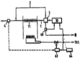
상기 기술적 과제를 해결하기 위한 본 발명의 기술적 수단은, 피가열회로와 바이패스 회로의 합류점의 하류쪽에 설치된 출탕온도 검지용의 제2서미스터와; 가스버너의 가스 회로내에 설치된 제2비례 제어밸브와; 출탕온도를 설정하기 위해 설치되는 출탕온도 설정기와; 상기 출탕온도 설정기로부터의 출력신호와 상기 제2서미스터로 부터의 출력신호를 비교하고 그 차에 대응하는 출력을 상기 제2비례 제어밸브에 인가시키는 제2구동회로와; 피가열 회로와 바이패스 회로의 분기점의 상류측 수온을 검지하기 위해 상기 분기점 상류측에 설치되는 입수온 검지수단과; 유량비율 조절밸브의 유량 비율을 제어하기 위해 상기 입수온검지수단의 출력과 상기 출탕온도 설정기로 부터의 출력을 비교하여 유량 비율 조정밸브로의 신호출력을 연산하는 연산 구동 회로를 구비하여 열 교환기의 드레인을 방지할 수 있도록 유량 비율 조정밸브를 구동하는 것을 특징으로 한다(제1도 참조).Technical means of the present invention for solving the above technical problem, the second thermistor for detecting the tapping temperature provided downstream of the junction of the heating circuit and the bypass circuit; A second proportional control valve installed in the gas circuit of the gas burner; A tapping temperature setting unit installed to set tapping temperature; A second drive circuit comparing the output signal from the tapping temperature setter with the output signal from the second thermistor and applying an output corresponding to the difference to the second proportional control valve; Water inlet temperature detecting means provided on the upstream side of the branch point to detect the water temperature upstream of the branch point of the circuit to be heated and the bypass circuit; In order to control the flow rate of the flow rate control valve, the operation of the heat exchanger includes an arithmetic driving circuit which compares the output of the water temperature detecting means with the output from the tapping temperature setting device and calculates the signal output to the flow rate adjusting valve. It is characterized by driving a flow rate control valve to prevent drainage (see FIG. 1).
본 발명의 상기 기술적 수단은 다음과 같이 작용한다. 열교환 작용이 행하여지고 있을때, 열교환기의 상류측으로 부터 공급되는 유체는, 바이패스회로(2)와 피가열회로(1)을 개재하여 하류쪽으로 흐른다. 피가열회로(1)을 지난 유체는 열교환기 내에서 열교환 되고 합류점의 하류쪽에서, 가열유체와 비가열유체가 혼합되어 소망하는 온도의 유체가 된다.The technical means of the present invention act as follows. When the heat exchange action is being performed, the fluid supplied from the upstream side of the heat exchanger flows downstream through the
여기서, 피가열관(11)을 가열하는 열량은 제2비례 제어밸브(62)의 출력에 의하여 소정 열량으로 설정된다. 동시에, 연산구동회로(30)이 출탕온도 설정기(64)로 부터의 신호입력과 입수온 검지수단(40)으로부터의 신호입력에 의하여 유량비율 조정밸브(3)의 동작량을 연산하고, 연산구동회로(30)으로 부터의 출력에 의하여 상기 유량비율 조정밸브(3)은 동작하고, 바이패스 회로(2)와 피가열 회로(1)과의 유량비율이 소정의 비율로 설정되어, 피가열관(11)측의 온도가 드레인이 발생하지 않은 정도로 유지된다. 즉, 출탕온도 설정기(64)의 설정치와 입수온에 의하여, 피가열관(11)측이 저온도측으로 이행하는 경향의 조건에 있을때에, 미리 이 피가열관측의 유량이 적어짐과 동시에 바이패스회로(2)측의 유량이 많아진다. 이에따라, 피가열관(11)측의 온도가 상승하여, 드레인이 발생하지 않을 정도로 유지케 된다. 또, 상기와는 역으로, 피가열회로(1)의 온도가 고온측으로 이행하는 경향의 조건에 있을때에는, 전술한 동작의 역 동작을 미리하여 피가열 회로(1)측의 온도를 일정하게 유지한다.Here, the heat quantity for heating the to-be-heated
본 발명은 상기 구성에 의해 다음과 같이 특유의 효과를 갖는다.This invention has the peculiar effect as follows by the said structure.
피가열회로(1)측이 항상 드레인이 발생하지 않을 정도의 온도로 설정됨과 동시에, 이 온도유지를 위한 조건설정이 입수온 변화 및 출탕온도 설정의 변화에 따라서 미리 선행하여 행하여지므로, 피가열관(11)에 드레인이 발생하여 이것이 열교환기내로 흘러내리는 결점이 확실히 방지된다. 또, 피가열관(11) 내부가 이상고온으로 가열되는 일도 없고, 열 교환기내에서의 비등현상이 방지된다.Since the side of the circuit to be heated 1 is always set to a temperature at which no drain occurs, the condition setting for maintaining the temperature is performed in advance according to the change in the water temperature and the tapping temperature. A drain is generated in (11), and the defect that it flows into the heat exchanger is surely prevented. Moreover, the inside of the to-be-heated
[실시예]EXAMPLE
이하, 본 발명 의 실시예를 제2도 내지 제5도를 참고로 설명한다.Hereinafter, embodiments of the present invention will be described with reference to FIGS. 2 to 5.
제2도 및 제3도에 도시한 제1실시예에서는, 대용량의 열교환을 가능케 하기 위하여, 제3도와 같이, 핀(12),(12)를 구비시킨 복수의 피가열관(11),(11)로 이루어지는 피가열관군(13),(14)을 2단으로 하고, 가열원으로서, 가스버너(15)가 사용된다. 따라서, 피가열관군(13),(14)는 관체(10)내에 상하 2단으로 배열되어 상호 연이어 통하게 접속되어서 아래쪽의 피가열관군(14)의 아래쪽을 연소실(16)으로 함과 동시에, 이 연소실에 있어서, 연소 용량을 크게하기 위하여, 팬(17)에 의하여 연소용 공기를 보내는 구성으로 하고 있다.In the first embodiment shown in Figs. 2 and 3, in order to enable a large heat exchange, as shown in Fig. 3, the plurality of
또, 관체(10)의 외부에는, 바이패스 회로(2)가 있어서, 피가열관군(13),(14) 양단부 상호를 연이어 통하도록 되어있다. 따라서, 물 회로를 흐르는 물의 일부는, 열교환기를 개재함이 없이, 분기점(21)로 부터 합류점(22)로 흐른다.Moreover, the
다음에, 전술한 입수온 검지수단(40)으로서 수온 또는 관벽온도를 검지하는 제1서미스터(41)이 사용되어, 분기점(21)의 상류쪽에 이 제1서미스터(41)이 설치됨과 동시에, 유량비율 조정밸브(3)로서의 제1비례 제어밸브(31)은 합류점(22) 근방의 바이패스 회로(2)에 삽입되어 있다.Next, the
상기 제1비례 제어밸브(31)은 공지의 구성으로서, 제1서미스터(41)에 인가되는 전압과, 출탕온도 설정기(64)의 설정전압을 비교 연산하여, 이 차에 응한 출력을 내도록한 연산 구동회로(30)에 의하여, 밸브의 열려진 정도가 변화하는 것이다.The first proportional control valve 31 has a known configuration, and compares the voltage applied to the
그리고, 합류점(22)의 하류쪽에 별개의 출탕온도 검지용의 제2서미스터(61)을 설치하고, 다시 가스버너(15)의 가스회로(7)내에 제2비례 제어밸브(62)을 삽입하고 있다. 이 제2비례 제어밸브(62)는, 제2구동회로(63)으로 부터의 출력에 의하여 밸브의 열려진 정도가 변화하여 가스버너의 연소량을 변화시키는 것으로서, 상기 제2구동회로(63)은, 출탕온도 설정기(64)로부터의 출력신호와 제2서미스터(61)로 부터의 출력신호를 비교함과 동시에, 그 차에 대응하는 출력을 제1비례 제어밸브(62)에 인가시킨다.Then, a
따라서, 피가열회로(1)과 바이패스 회로(2)의 유량비율의 여하에 또, 탕량변화에도 불구하고, 출탕온도가 설정온도로 유지된다.Therefore, the tapping temperature is maintained at the set temperature in spite of the change in the amount of hot water in addition to the flow rate ratio between the
여기서, 출탕온도 설정기(64)에 의하여 출탕온도가 설정되면 이때에 피가열회로-바이패스 회로 분배비율에 알맞는 출력상태에서 제2비례 제어밸브(62)가 동작하여 출탕온도는 소정의 온도로 설정된다. 동시에, 입수온도에 상기 출탕온도의 설정치, 및 피가열 회로의 피가열관(11),(11)에 드레인 발생하지 않은 온도(예컨대 55℃)로 가열하는데 요하는 가스량과의 관계로 부터, 연산 구동 회로(30)이 유량 비율 조정밸브(3)의 동작량을 연산함과 아울러 이 연산결과에 응한 출력 동작을 행하여, 피가열회로(1)와 바이패스 회로(2)와의 유량비율이 소정대로 설정되게끔 된다. 이후는 출탕량이 변화하여도, 이 설정 유량비율이 유지된채로 제2비례 제어밸브(62)가 제어동작을 행하여 출탕온도가 설정 온도로 유지된다.Here, when the tapping temperature is set by the tapping
이 관계를 수식을 사용하여 다시 상세하게 설명한다. 여기서, 출탕온도:(T), 입수온도:(To), 피가열관 가열온도:(T1), 총 유량:(Q), 피가열회로 유량:(Q1), 바이패스 회로 유량(Q2)로 하고, 바이패스 회로의 유량과 피가열 회로의 유량과의 비율을 (k)라 하면, 다음식이 성립한다.This relationship is explained again in detail using equations. Here, tapping temperature: (T), inlet temperature: (To), heating tube heating temperature: (T 1 ), total flow rate: (Q), heating circuit flow rate: (Q 1 ), bypass circuit flow rate (Q 2 ), and the ratio between the flow rate of the bypass circuit and the flow rate of the circuit to be heated is (k), the following equation is established.
Q2/Q2=k ㆍ ㆍㆍㆍㆍㆍㆍㆍㆍㆍㆍㆍㆍㆍㆍㆍㆍㆍㆍㆍㆍㆍㆍㆍㆍ(1)식Q 2 / Q 2 = k ㆍ ························· Equation (1)
Q=Q1+Q2ㆍ ㆍㆍㆍㆍㆍㆍㆍㆍㆍㆍㆍㆍㆍㆍㆍㆍㆍㆍㆍㆍㆍ ㆍㆍ (2)식Q = Q 1 + Q 2 ㆍ ······················ Equation (2)
열교환 총열량은 회로(1)의 가열량에 상당함으로,Heat exchange total heat amount corresponds to the heating amount of the circuit (1),
Q1(T1-TO)=Q(T-TO)ㆍㆍㆍㆍㆍㆍㆍㆍㆍㆍㆍㆍㆍㆍㆍㆍㆍㆍㆍㆍ (3)식Q 1 (T 1 -T O ) = Q (TT O ) ·············
(1),(2)식에서 Q=(1+k)Q1이것을 (3)식에 대입하면,In equations (1) and (2), Q = (1 + k) Q 1 Substituting this into equation (3),
Q1(T1-TO)=(T-TO)·(1+k)Q1ㆍㆍㆍㆍㆍㆍㆍㆍㆍㆍㆍㆍㆍㆍㆍㆍㆍ (4)식Q 1 (T 1 -T O ) = (TT O ) · (1 + k) Q 1 Equation (4)
따라서, 다음식이 성립한다.Therefore, the following equation holds.
k=[(T1-To)/(T-TO)]-1k = [(T 1 -T o ) / (TT O )]-1
이와 같이, 입수온도와 출탕 설정 온도로 부터 상기 비율(k)를 설정하면, 출탕량의 여하에 불구하고, 피가열관(11),(11)의 필요 가열량이 결정된다.Thus, if the said ratio k is set from the water acquisition temperature and the tapping set temperature, the required heating amount of the to-
따라서, 연산 구동 회로(30)에서는, 피가열관(11),(11)의 필요 가열 온도의 최소치(예컨대 35℃)와, 입수온도 및 출탕 설정 온도로 부터 분배 비율울 연산하게 된다. 이 연산결과에 의거 유량비율 조정밸브(3)으로서의 제1비례 제어밸브(31)이 동작함과 동시에, 그 후에 있어서는 제2비례 제어밸브(62)의 출력에 의하여, 출탕온도가, 탕량(끓는 물의 양)의 변화에도 불구하고, 설정온도로 유지된다.Therefore, in the
상기한 바와 같이 2개의 비례 제어밸블을 조합시킴으로써, 출탕온도 및 출탕량을 넓은 범위에서 변화시킬수 있음과 동시에, 이 조절범위에서의 피가열관은 드레인의 발생 및 흘러내림이 방지된다.By combining two proportional control valves as described above, the tapping temperature and tapping amount can be varied in a wide range, and the heating tube in this adjusting range is prevented from generating and flowing down the drain.
이상의 제1실시예에 있어서, 유량비율 조정밸브(3)으로서, 제1비례 제어밸브(31)을 사용해서 바이패스회로(2)의 하류 단부에 설치하였으나, 이 비례 제어밸브(31)의 삽입위치는, 바이패스 회로(2)의 어느 위치에 설정하여도 된다.In the first embodiment described above, the flow rate ratio control valve 3 is provided at the downstream end of the
제1실시예의 경우에, 바이패스 회로(2)의 유량을 조절함으로서, 양회로의 유량비율을 변화시킬 수 있으나 직접 유량비율을 변화시키는 일도 가능하다.In the case of the first embodiment, by adjusting the flow rate of the
이 방법으로서, 예컨대, 제4도에 도시되어진 바와 같이 유량비율 조정밸브로서의 밸브체(32)를 분기점(21)에 삽입하거나 또는 합류점(22)에 삽입하는 구성이 사용된다.As this method, for example, as shown in Fig. 4, a configuration in which the valve body 32 as the flow rate ratio regulating valve is inserted into the
이 경우에, 밸브체(32)가 출력기구(33)에 의하여 이동케되어, 바이패스 회로(2)측의 유량과 피가열회로(1)측의 유량과의 비율이 직접적으로 변화한다. 그리고, 이 경우에 있어서도, 전술한 비례 제어밸브와 마찬가지로, 입수온도와 설정온도와의 관계로 부터 분배비율을 연산하고, 이 연산결과에 응한 출력이 연산구동회로(30)으로 부터 출력기구에 입력케 된다.In this case, the valve body 32 is moved by the output mechanism 33, and the ratio between the flow rate on the
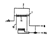
또, 제5도와 같이, 유량비율 조정밸브(3)을 열교환기에의 입구쪽에 설치토록 하여도, 본 발명의 기술의 작용 효과에는 변함이 없다. 그리고 제2도의 2점 쇄선으로 보이듯이, 입수온 검지수단인 제1서미스터(41)의 상류측에 전수량 제어밸브(42)를 설치하고, 가스버너(15)의 능력을 초과하는 설정 조건하에서는 이 전수량 제어밸브(42)을 연산구동회로(30)으로부터의 출력에 의하여 유량 제한 상태로 세트하도록 하면, 입수온이 극단으로 낮은 경우에 있어서, 설정온도의 뜨거운 물이 나오지 않는다고 하는 부적합이 방지된다. 이 경우, 연산구동회로(30)에는 입수온과 설정온과의 비교에 의하여, 전수량 제어 밸브(42)를 구동시키기 위한 연산기능이 부가 가능하다.Also, as shown in FIG. 5, even if the flow rate ratio regulating valve 3 is provided at the inlet side of the heat exchanger, the effect of the technique of the present invention does not change. And as shown by the dashed-dotted line of FIG. 2, the whole
Claims (2)
Applications Claiming Priority (3)
| Application Number | Priority Date | Filing Date | Title |
|---|---|---|---|
| JP62-325794 | 1987-12-22 | ||
| JP62325794A JPH01167554A (en) | 1987-12-22 | 1987-12-22 | Heat exchanger of hot water feed appliance |
| JP??62-325794 | 1987-12-22 |
Publications (2)
| Publication Number | Publication Date |
|---|---|
| KR890010528A KR890010528A (en) | 1989-08-09 |
| KR930003986B1 true KR930003986B1 (en) | 1993-05-19 |
Family
ID=18180672
Family Applications (1)
| Application Number | Title | Priority Date | Filing Date |
|---|---|---|---|
| KR1019880016574A KR930003986B1 (en) | 1987-12-22 | 1988-12-13 | Water rate control device in hot water boiler |
Country Status (2)
| Country | Link |
|---|---|
| JP (1) | JPH01167554A (en) |
| KR (1) | KR930003986B1 (en) |
Families Citing this family (6)
| Publication number | Priority date | Publication date | Assignee | Title |
|---|---|---|---|---|
| JPH0579696A (en) * | 1991-09-25 | 1993-03-30 | Harman Co Ltd | Hot water supply controller |
| JP2830548B2 (en) * | 1991-11-05 | 1998-12-02 | リンナイ 株式会社 | Water heater |
| JP2560589B2 (en) * | 1992-02-26 | 1996-12-04 | 株式会社ノーリツ | Hot water supply method for instantaneous water heater |
| KR100232565B1 (en) * | 1996-03-19 | 2000-01-15 | 나이토 스스무 | Water supplier |
| JP5200748B2 (en) * | 2008-08-08 | 2013-06-05 | 株式会社ノーリツ | Water heater |
| JP7040750B2 (en) * | 2017-10-03 | 2022-03-23 | 株式会社パロマ | Water heater |
Family Cites Families (6)
| Publication number | Priority date | Publication date | Assignee | Title |
|---|---|---|---|---|
| JPS58205043A (en) * | 1982-05-26 | 1983-11-29 | Paloma Ind Ltd | Tap-controlled type hot-water supplying machine equipped with automatic mixer |
| JPS58224246A (en) * | 1982-06-21 | 1983-12-26 | Matsushita Electric Ind Co Ltd | Heating controller |
| JPS59103157U (en) * | 1982-12-28 | 1984-07-11 | 株式会社ノーリツ | water heater |
| JPS6095439U (en) * | 1983-12-06 | 1985-06-29 | 株式会社ノーリツ | Water heater |
| JPS6251381A (en) * | 1985-08-30 | 1987-03-06 | Mitsubishi Electric Corp | Infrared ray image pickup device |
| JPS6260624A (en) * | 1985-09-12 | 1987-03-17 | Casio Comput Co Ltd | Injection compression molding method for straight-hydraulic mold clamping system |
-
1987
- 1987-12-22 JP JP62325794A patent/JPH01167554A/en active Granted
-
1988
- 1988-12-13 KR KR1019880016574A patent/KR930003986B1/en not_active IP Right Cessation
Also Published As
| Publication number | Publication date |
|---|---|
| KR890010528A (en) | 1989-08-09 |
| JPH056099B2 (en) | 1993-01-25 |
| JPH01167554A (en) | 1989-07-03 |
Similar Documents
| Publication | Publication Date | Title |
|---|---|---|
| KR930003986B1 (en) | Water rate control device in hot water boiler | |
| KR0142396B1 (en) | Hot-water supplier | |
| KR930020114A (en) | Hot water supply control device | |
| JPS60259855A (en) | Hot water supplying temperature control device of gas-fired water heater | |
| KR0153714B1 (en) | Heating apparatus | |
| JPH0341738B2 (en) | ||
| JP2560578B2 (en) | Bypass mixing type water heater | |
| JP3530576B2 (en) | Water heater | |
| JP3553701B2 (en) | Hot water heating system | |
| JPH0633903B2 (en) | Bypass mixing type water heater | |
| JP3021934B2 (en) | Hot water heating system | |
| JP4082789B2 (en) | Combustion device for bath | |
| JP2589237Y2 (en) | One-can two-circuit water heater | |
| JP3785197B2 (en) | Solar hot water heater | |
| JP2002156101A (en) | Number of sets control method for fluid heater | |
| KR930001209Y1 (en) | Anti-freezing method in gas boiler | |
| JP3663649B2 (en) | Water heater | |
| JPH02183760A (en) | Hot water feeding temperature control in water heater | |
| JPS60207847A (en) | Instantaneous water heater | |
| JP2988875B2 (en) | Instant water heater | |
| JPH08219447A (en) | Gas boiler with combustion abnormality detecting function | |
| JPS6131397B2 (en) | ||
| JPH05149568A (en) | Tap-controlled hot-water supplying apparatus | |
| JPS586847B2 (en) | Jiyunkanshiki Yuwakashiki | |
| KR930010491A (en) | Water heater |
Legal Events
| Date | Code | Title | Description |
|---|---|---|---|
| A201 | Request for examination | ||
| E902 | Notification of reason for refusal | ||
| E902 | Notification of reason for refusal | ||
| G160 | Decision to publish patent application | ||
| E701 | Decision to grant or registration of patent right | ||
| GRNT | Written decision to grant | ||
| FPAY | Annual fee payment |
Payment date: 20080507 Year of fee payment: 16 |
|
| EXPY | Expiration of term |