KR930001954B1 - Circuit breaker alarm-switch operating apparatus - Google Patents
Circuit breaker alarm-switch operating apparatus Download PDFInfo
- Publication number
- KR930001954B1 KR930001954B1 KR1019900005851A KR900005851A KR930001954B1 KR 930001954 B1 KR930001954 B1 KR 930001954B1 KR 1019900005851 A KR1019900005851 A KR 1019900005851A KR 900005851 A KR900005851 A KR 900005851A KR 930001954 B1 KR930001954 B1 KR 930001954B1
- Authority
- KR
- South Korea
- Prior art keywords
- latch
- circuit breaker
- alarm
- switch
- crossbar
- Prior art date
Links
Images


Classifications
-
- H—ELECTRICITY
- H01—ELECTRIC ELEMENTS
- H01H—ELECTRIC SWITCHES; RELAYS; SELECTORS; EMERGENCY PROTECTIVE DEVICES
- H01H73/00—Protective overload circuit-breaking switches in which excess current opens the contacts by automatic release of mechanical energy stored by previous operation of a hand reset mechanism
- H01H73/02—Details
- H01H73/12—Means for indicating condition of the switch
-
- H—ELECTRICITY
- H01—ELECTRIC ELEMENTS
- H01H—ELECTRIC SWITCHES; RELAYS; SELECTORS; EMERGENCY PROTECTIVE DEVICES
- H01H71/00—Details of the protective switches or relays covered by groups H01H73/00 - H01H83/00
- H01H71/10—Operating or release mechanisms
- H01H71/12—Automatic release mechanisms with or without manual release
- H01H71/46—Automatic release mechanisms with or without manual release having means for operating auxiliary contacts additional to the main contacts
- H01H71/465—Self-contained, easily replaceable microswitches
-
- H—ELECTRICITY
- H01—ELECTRIC ELEMENTS
- H01H—ELECTRIC SWITCHES; RELAYS; SELECTORS; EMERGENCY PROTECTIVE DEVICES
- H01H71/00—Details of the protective switches or relays covered by groups H01H73/00 - H01H83/00
- H01H71/08—Terminals; Connections
- H01H2071/086—Low power connections for auxiliary switches, e.g. shunt trip
-
- H—ELECTRICITY
- H01—ELECTRIC ELEMENTS
- H01H—ELECTRIC SWITCHES; RELAYS; SELECTORS; EMERGENCY PROTECTIVE DEVICES
- H01H71/00—Details of the protective switches or relays covered by groups H01H73/00 - H01H83/00
- H01H71/10—Operating or release mechanisms
- H01H71/12—Automatic release mechanisms with or without manual release
- H01H71/46—Automatic release mechanisms with or without manual release having means for operating auxiliary contacts additional to the main contacts
- H01H2071/467—Automatic release mechanisms with or without manual release having means for operating auxiliary contacts additional to the main contacts with history indication, e.g. of trip and/or kind of trip, number of short circuits etc.
-
- H—ELECTRICITY
- H01—ELECTRIC ELEMENTS
- H01H—ELECTRIC SWITCHES; RELAYS; SELECTORS; EMERGENCY PROTECTIVE DEVICES
- H01H71/00—Details of the protective switches or relays covered by groups H01H73/00 - H01H83/00
- H01H71/10—Operating or release mechanisms
- H01H71/50—Manual reset mechanisms which may be also used for manual release
- H01H71/505—Latching devices between operating and release mechanism
- H01H2071/508—Latching devices between operating and release mechanism with serial latches, e.g. primary latch latched by secondary latch for requiring a smaller trip force
-
- H—ELECTRICITY
- H01—ELECTRIC ELEMENTS
- H01H—ELECTRIC SWITCHES; RELAYS; SELECTORS; EMERGENCY PROTECTIVE DEVICES
- H01H71/00—Details of the protective switches or relays covered by groups H01H73/00 - H01H83/00
- H01H71/10—Operating or release mechanisms
- H01H71/50—Manual reset mechanisms which may be also used for manual release
- H01H71/505—Latching devices between operating and release mechanism
-
- H—ELECTRICITY
- H01—ELECTRIC ELEMENTS
- H01H—ELECTRIC SWITCHES; RELAYS; SELECTORS; EMERGENCY PROTECTIVE DEVICES
- H01H71/00—Details of the protective switches or relays covered by groups H01H73/00 - H01H83/00
- H01H71/10—Operating or release mechanisms
- H01H71/50—Manual reset mechanisms which may be also used for manual release
- H01H71/52—Manual reset mechanisms which may be also used for manual release actuated by lever
- H01H71/522—Manual reset mechanisms which may be also used for manual release actuated by lever comprising a cradle-mechanism
- H01H71/525—Manual reset mechanisms which may be also used for manual release actuated by lever comprising a cradle-mechanism comprising a toggle between cradle and contact arm and mechanism spring acting between handle and toggle knee
Abstract
내용 없음.No content.
Description
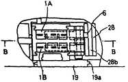
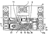
제1a도는 트립동작 시작점에서의 경보스위치 장치부의 평면도.1A is a plan view of the alarm switch device unit at the starting point of the trip operation.
제1b도는 제1a도의 B-B선을 따라 취한 단면도.FIG. 1B is a sectional view taken along the line B-B in FIG. 1A.
제2a도는 트립동작 완료점에서의 경보스위치 장치부의 평면도.2A is a plan view of the alarm switch device unit at the trip operation completion point.
제2b도는 제2a도의 B-B선을 따라 취한 단면도.FIG. 2B is a sectional view taken along the line B-B in FIG. 2A.
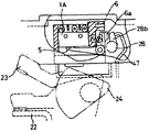
제3도는 투입상태에서의 개폐기구부의 측면도.3 is a side view of the opening and closing mechanism in the closed state.
제4도는 트립동작 시작점에서의 개폐기구부의 측면도.4 is a side view of the opening and closing mechanism at the starting point of the trip operation.
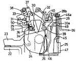
제5a도는 트립동작 완료시점에서의 개폐기구부의 측면도.Fig. 5A is a side view of the opening and closing mechanism at the time of trip completion.
제5b도는 제5a도의 화살표 P 방향에서 본 정면도.FIG. 5B is a front view as seen in the arrow P direction of FIG. 5A; FIG.
제6a도는 래치리시버의 정면도.6A is a front view of the latch receiver.
제6b도는 제6a도의 화살표 P 방향에서 본 정면도.FIG. 6B is a front view seen from the arrow P direction of FIG. 6A; FIG.
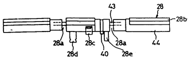
제7a도는 이 크로스바의 평면도.7A is a plan view of this crossbar.
제7b도는 이 크로스바의 정면도.7b is a front view of this crossbar.
제7c도는 제7b도의 C-C선을 따라서 취한 단면도.FIG. 7C is a cross-sectional view taken along the line C-C of FIG. 7B.
제7d도는 제7b도의 D-D선을 따라서 취한 단면도.FIG. 7D is a sectional view taken along the line D-D of FIG. 7B.
제8도는 크로스바의 다른 실시예를 도시하는 제7d도에 상당하는 단면도.FIG. 8 is a cross-sectional view corresponding to FIG. 7D showing another embodiment of the crossbar. FIG.
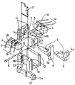
제9도는 스위치유니트의 분해사시도.9 is an exploded perspective view of the switch unit.
제10a도는 조립된 상태의 스위치유니트의 평면도.Figure 10a is a plan view of the switch unit in the assembled state.
제10b도는 조립된 상태의 스위치유니트의 측면도.Figure 10b is a side view of the switch unit in the assembled state.
제10c도는 제10b도의 화살표 R 방향에서 본 조립상태의 스위치유니트의 정면도.10C is a front view of the switch unit in an assembled state as seen from the arrow R direction in FIG. 10B.
제11a도는 좌측반의 내부가 보이도록 일부분을 잘라낸 회로차단기의 평면도.11A is a plan view of a circuit breaker with a portion cut away so that the inside of the left half is visible.
제11b도는 제11a도의 B-B선을 따라 취한 회로차단기의 단면도.FIG. 11B is a cross-sectional view of the circuit breaker taken along the B-B line of FIG. 11A.
* 도면의 주요부분에 대한 부호의 설명* Explanation of symbols for main parts of the drawings
1 : 스위치유니트 1A : 경보스위치1: Switch
1B : 보조스위치 6, 7 : 액튜에이터1B:
22 : 고정접촉자 23 : 가동접촉자22: fixed contact 23: movable contact
24 : 홀더 25 : 과전류 트립장치24 holder 25 overcurrent trip device
28 : 크로스바 30 : 래치28: crossbar 30: latch
30a, 40 : 걸림쇠 32 : 래치리시버30a, 40: latch 32: latch receiver
35 : 토글링크 37 : 핸들레버35: toggle link 37: handle lever
38 : 개폐스프링 44 : 절연봉38: opening and closing spring 44: insulating rod
45 : 히터 46 : 아머츄어45: heater 46: amateur
47 : 고정자석 49 : 바이메탈47: stator magnet 49: bimetal
50 : 스토퍼50: stopper
본 발명은 소형회로차단기에 내장한 경보스위치를 조작하기 위한 장치에 관한 것이다.The present invention relates to an apparatus for operating an alarm switch built in a small circuit breaker.
배선용 차단기와 같은 회로차단기에는 단락등의 사고로 인하여 트립동작이 수행되는 경우에 먼 장소에 경보신호를 보내기 위한 경보스위치가 내장되어 있다. 이러한 경보스위치에서, 마이크로스위치는 스위치본체로서 사용되며, 일반적으로 회로차단기의 좌측극 또는 우측극에 설치된다.Circuit breakers such as wiring breakers have built-in alarm switches for sending alarm signals to remote locations in the event of a trip operation due to an accident such as a short circuit. In such an alarm switch, the microswitch is used as the switch body and is generally installed at the left pole or the right pole of the circuit breaker.
이러한 종래의 회로차단기 구조에서는 회로차단기가 트립동작을 수행하는 경우에 경보스위치가 동작하도록 하기 위하여 개폐기구의 구성부재의 하나인 중앙극 부분의 래치에 개폐스프링의 스프링력에 반응하여 회전하는 경보스위치 액튜에이터를 직접 접촉하도록 설치하거나, 또는 래치에 접속된 조작봉과 접촉하도록 경보스위치 액튜에이터를 배열하여 측방향으로 돌출시켰다(예를들면, 일본 실용신안 공고공보 제58-24362호).In the conventional circuit breaker structure, the alarm switch rotates in response to the spring force of the opening / closing spring on the latch of the central pole part, which is one of the constituent members of the opening / closing mechanism, so that the alarm switch operates when the circuit breaker performs the trip operation. The actuators were installed to be in direct contact with each other, or the alarm switch actuators were arranged to protrude laterally so as to contact the operating rods connected to the latches (for example, Japanese Utility Model Publication No. 58-24362).
그러나, 상술한 종래의 구성에는 다음과 같은 결점이 있다. 경보스위치 액튜에이터를 래치에 직접 접촉시키기에는 래치가 소형이어서 두개의 경보스위치 액튜에이터를 동시에 접촉시키기가 불가능하므로 경보스위치를 차단기의 좌측극 또는 우측극에만 설치할 수 있으며 양쪽극에 모두 설치할 수 없다.However, the above-described conventional configuration has the following drawbacks. The alarm switch can be installed only on the left or right pole of the breaker and cannot be installed on both poles because the latch is so small that it is impossible to contact two alarm switch actuators at the same time.
반면에 경보스위치 액튜에이터를 래치에 결합된 조작봉에 접합시키는 것은 두 경보스위치가 조작봉에 대하여 축방향을 따라 나란히 배치되면 배치의 한쪽측면에 설치할 수 있다. 그렇지 않고 조작봉이 좌ㆍ우측으로 돌출되어 배치되면 회로차단기의 좌측극과 우측극에 설치할 수 있다. 그러나 이러한 구조에서 조작봉은 래치가 회전할때 회전할 수 있도록 본체케이스의 좌ㆍ우측극 사이의 격벽을 넘어 인장되어야만 한다.On the other hand, joining the alarm switch actuator to an operating rod coupled to the latch can be installed on one side of the arrangement if the two alarm switches are arranged side by side along the axial direction with respect to the operating rod. Otherwise, if the operating rod protrudes left and right, it can be installed on the left and right poles of the circuit breaker. However, in this structure, the operating rod must be tensioned beyond the partition wall between the left and right poles of the main body case so that the latch can rotate when the latch rotates.
따라서 좌ㆍ우측극 사이의 격벽에는 큰 창이 개방되어 있어야만 하므로 두 경보스위치와 회로차단기의 중앙극 부분에 있는 도체사이의 절연에 문제가 생긴다. 특히 두 경보스위치가 래치의 한쪽 측면에 설치되는 경우에는 중앙극 부근의 경보스위치의 절연이 어려워진다.Therefore, since a large window must be opened in the partition wall between the left and right poles, there is a problem in the insulation between the two alarm switches and the conductor in the center pole of the circuit breaker. In particular, when two alarm switches are provided on one side of the latch, insulation of the alarm switch near the center pole becomes difficult.
본 발명의 목적은 선행기술과 관련한 문제점을 해결하기 위한 것이다.It is an object of the present invention to solve the problems associated with the prior art.
본 발명의 다른 목적은 경보스위치의 절연에 손상을 가하지 않고 다수의 경보스위치를 용이하게 설치한 회로차단기의 경보스위치 조작장치를 제공하기 위한 것이다.Another object of the present invention is to provide an alarm switch operating device of a circuit breaker which is easily provided with a plurality of alarm switches without damaging the insulation of the alarm switch.
본 발명의 기타의 목적 및 이점은 후술할 설명의 일부분으로부터 부분적으로 명확해지기도 할 것이나 본 발명을 실시함으로써 체득될 수도 있을 것이다. 본 발명의 목적 및 이점은 특히 첨부한 청구범위에 기재된 요소 및 조합에 의해 획득되고 실현될 것이다.Other objects and advantages of the invention will be in part apparent from part of the following description, but may be learned by practice of the invention. The objects and advantages of the invention will be obtained and realized in particular by the elements and combinations set forth in the appended claims.
상기 목적을 달성하기 위한 본 발명에 의한 경보스위치 조작장치는 트립동작시 래치의 회전에 의해 래치리시버를 개재하여 회로차단기 크로스바를 트립위치로부터 회전하므로 경보스위치 액튜에이터는 경보스위치로 동작한다. 과전류 트립장치의 동작에 의해 래치리시버와 래치선단부에 설치된 걸림쇠 사이의 결합이 해제되도록 크로스바가 트립위치로 회전하면 래치는 걸림이 풀어져 개폐스프링의 스프링력에 의해 회전한다. 래치의 이 운동은 래치리시버를 개재하여 크로스바에 전달되어 트립위치로부터 크로스바를 다시 회전시킨다. 크로스바의 절연봉이 회로차단기의 좌ㆍ우측극을 가로질러 뻗어 있기 때문에 경보스위치 액튜에이터가 절연봉의 회전에 의해 동작되도록 배열되면 회로차단기 좌ㆍ우측극의 어느하나 또는 양쪽에 2개의 경보스위치를 용이하게 설치할 수 있다. 또 본체케이스의 극들 사이의 격벽에 있는 창을 개방할 필요가 있으므로 극들 사이의 절연이 결코 손상되지 않는다.The alarm switch operating device according to the present invention for achieving the above object rotates the circuit breaker crossbar from the trip position via the latch receiver by the rotation of the latch during the trip operation, so the alarm switch actuator operates as an alarm switch. When the crossbar rotates to the trip position to release the engagement between the latch receiver and the latch provided at the latch end by the operation of the overcurrent trip device, the latch is released and rotated by the spring force of the open / close spring. This movement of the latch is transmitted to the crossbar via the latch receiver to rotate the crossbar again from the trip position. Since the insulated rod of the crossbar extends across the left and right poles of the circuit breaker, if the alarm switch actuator is arranged to operate by the rotation of the insulated rod, two alarm switches are easily provided on either or both of the left and right poles of the circuit breaker. Can be installed. In addition, since the windows in the partitions between the poles of the main body case need to be opened, the insulation between the poles is never damaged.
상술한 일반 설명과 후술할 상세한 설명은 모범적이고 설명적인 것에 불과하며 청구항에서처럼 본 발명을 제한하는 것이 아니라는 점을 이해하여야 할것이다.It is to be understood that the foregoing general description and the following detailed description are exemplary and explanatory only and do not limit the invention as claimed.
본 명세서에 포함되어 그 일부를 구성하고 있는 첨부도면은 본 발명의 몇몇 실시예 및 그 상세한 설명과 함께 본 발명의 원리를 설명하기 위한 것이다. 본 발명의 다른 특징 및 이점은 배선차단기에 부착된 본 발명의 실시예를 도시한 첨부도면과 관련하여 취한 다음 설명으로부터 분명해질 것이다.BRIEF DESCRIPTION OF THE DRAWINGS The accompanying drawings, which are incorporated in and constitute a part of this specification, are intended to illustrate the principles of the invention, together with some embodiments of the invention and a detailed description thereof. Other features and advantages of the present invention will become apparent from the following description taken in conjunction with the accompanying drawings, which illustrate an embodiment of the invention attached to a circuit breaker.
이제 본 발명의 바람직한 실시예에 대하여 상세히 참고번호를 붙인다. 첨부도면에는 본 발명의 예들이 도시되어 있다. 가능하면 동일한 부호는 전 도면을 통하여 동일한 부위를 인용하는데 사용될 것이다.Reference is now made in detail to preferred embodiments of the invention. Examples of the invention are shown in the accompanying drawings. Wherever possible, the same reference numerals will be used to refer to the same parts throughout the drawings.
제9도 및 제10도에 도시된 바처럼 스위치유니트(1)는 H자형의 프레임(2)의 양면에 구비된 가이드핀(3)이 각 고정구(4)에 끼워지도록 유니트의 형태로 배열된 마이크로스위치(1A) 및 (1B)를 구비한다. 마이크로스위치(1A) 및 (1B)의 하면에 있는 푸시버튼(5)을 동작시키기 위한 액튜에이터(6) 및 (7)은 마이크로스위치(1A) 및 (1B)를 온ㆍ오프 동작시키고, 프레임(2)의 일단에 부착되어서 축(8)을 개재하여 회전한다. 프레임(2)과 각 액튜에이터(6) 및 (7) 사이에는 각각 복귀스프링(9), 예를들면 압축스프링이 있다. 제9도 및 제10도의 실시예에서 마이크로스위치(1A)는 회로차단기에 의해 수행되는 트립동작을 검출하는 경보스위치로 사용되며, 마이크로스위치(1B)는 회로차단기에 의해 수행되는 통상 개폐동작을 검출하는 보조스위치로 사용된다. 후술하는 바와 같이 액튜에이터(6) 및 (7)은 액튜에이터(6)의 동작부(6a)가 크로스바와 접하고, 액튜에이터(7)의 동작부(7a)가 가동접촉자를 지지하는 홀더의 동작부재와 접하도록 구성된다. 프레임(2)은 U자형 단면을 가지는 베이스(10)에 의해 지지된다. 베이스(10)에 프레임(2)을 고착시키기 위하여 프레임(2)의 양면에 구비된 가이드부재(11)를 베이스(10)에 대응하여 구비된 가이드홈(12)에 삽입한다. 마이크로스위치(1A) 및 (1B)의 리드선(14) 및 (15)을 인출하기 위하여 배선홈(13)을 설치한다. 그러나 마이크로스위치(1A)의 리드선(14)은 프레임(2)의 상면에 구비된 배선가이드(16)를 개재하여 배선홈(13)을 인출되는 반면, 마이크로스위치(1B)의 리드선(15)은 직접 배선홈(13)으로 인출된다. 리드선(14) 및 (15)가 배선홈(13)에 수용되면 선 누름부재(17)를 베이스(10)의 가이드홈(18)에 삽입하여 끼워 넣는다. 그리고 리드선(14) 및 (15)를 선누름부재(17)의 하측으로부터 베이스(10)측으로 수평방향으로 일렬로 정렬시킨 상태로 인출한다.As shown in FIG. 9 and FIG. 10, the
제11도에 도시된 바처럼 조립된 스위치유니트(1)는 베이스(10)에 일체로 구비된 고정각(19)을 사용하여 회로차단기에 고정할 수 있다(리드선등 상세한 부분은 생략) 회로차단기는 본체케이스(20), 본체케이스(20)를 씌우는 덮개(21), 전원측 단자에 일체로 구비되는 고정접촉자(22), 고정접촉자(22)에 대응하여 접촉ㆍ분리하도록 배치된 가동접촉자(23), 가동접촉자(23)를 지지하기 위하여 회전가능하게 설치된 홀더(24), 옆에 의해 가동되는 전기자기(전자)식 과전류 트립장치(25), 가동접촉자(23)를 과전류 트립장치(25)에 연결하는 리드선(26) 및 부하측 단자(27)를 구비한다. 제9도 및 제10도에 도시된 스위치유니트(1)는 회로차단기의 좌측극에 설치되어, 고정각(19)이 본체케이스(20)의 좌벽(20a)에 형성된 노치(이 노치는 고정각(19)의 기하학적 윤곽에 따라 형성됨)속에 끼워맞춰지는 방식으로 회로차단기에 고정된다. 제11a도에 도시된 바처럼 제2스위치유니트(1)는 경보스위치(1A)의 액튜에이터(6)가 크로스바(28)에 의해 동작하도록 회로차단기의 우측극에 설치된다. 크로스바(28)의 형상을 이하에서 설명한다.The
제3도, 제4도 및 제5도는 제11도 회로차단기의 중앙극에 설치한 개폐기구부를 도시한다.3, 4, and 5 show the opening and closing mechanism provided at the central pole of the circuit breaker of FIG.
제3도에서 래치(30)는 축(31)을 개재하여 회전하도록 개폐기구의 측판(29)에 의해 지지된다. 통상, 래치(30)는 래치(30)의 선단에 있는 걸림쇠(30a)가 래치리시버(32)에 의해 걸려 있기 때문에 회전이 지지된다. 홀더(24)와 래치(30)는 상ㆍ하링크(34)로된 토글링크(35)에 의해 서로 연결되어 있다. 개폐스프링(38)은 토글링크(35)의 중앙연결핀(36)과 측판(29)에 의해 회전가능하게 지지되는 핸들레버(37) 사이에 부착되어 있다. 회로차단기의 투입상태에서 래치(30)는 개폐스프링(38)의 스프링력에 의해 반시계방향의 회전력을 받으나, 이 회전력은 래치리시버(32)에 의해 지탱된다. 이와 같이 축(39) 둘레를 회전하도록 측판(29)에 의해 지지된 래치리시버(32)는 시계방향의 회전력을 받는다. 그러나 시계방향의 회전력은 래치리시버(32)의 배면과 결합하는 크로스바(28)에 의해 지탱된다. 또 크로스바(28)는 측판(29)에 의해 회전가능하게 지지된다.In FIG. 3 the
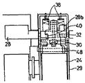
제6도에 도시된 바처럼 강판으로 된 래치리시버(32)는 그 좌ㆍ우측 단부를 구부려 형성시킨 지지팔(32a)을 구비하고 있다. 이 지지팔(32a)에는 축(39)(제3도에 도시)이 삽입되어 래치리시버(32)를 지지하도록 하는 베어링구멍(41)이 형성되어 있다. 래치리시버(32)의 선단부는 종래의 래치리시버 보다 더 연장되어 있으며 제6b도에 도시된 바와 같이 두번 구부러 래치(30)의 회전력을 받는 부재(32b)이다. 상술한 크로스바(28)의 걸림쇠(40)는 결합부재(31c)의 배면에 결합되고 래치(30)의 걸림쇠(30a)는 결합창(32d)의 상부 가장자리에 결합된다. 또 래치리시버(32)는 크로스바(28)를 위치결정하는 스토퍼부재(32e)와 해제된 래치(30)를 재설정하는 리세트부재(32f)를 포함한다.As shown in FIG. 6, the
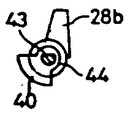
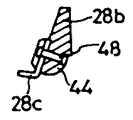
제7a도, 제7b도에 도시된 바와 같이 크로스바(28)는 코어금속(43)상에 몰드성형된 절연봉(44) 및 절연봉(44)에 결합된 걸림쇠(40)로 구성된다. 크로스바(28)는 코어금속(43)이 부분적으로 노출된 홈부(28a)에서 제5b도의 축판(29)에 의해 지지된다. 걸림쇠(40)는 1/4 원호의 윤곽을 가지며, 그 베이스부는 절연봉(44)의 몰드성형에 앞서 코어금속(43)에 밀어 넣어진다.As shown in FIGS. 7A and 7B, the
크로스바(28)에는 제3도의 과전류 트립장치(25)의 조작력을 받는 팔(28b)이 회로차단기의 각 극에 대하여 형성되어 있다. 후술하는 바와 같이 래치리시버(32)로부터 가해진 회전력을 수용하는 돌기부재(28c)는 크로스바(28)의 중앙부분에 팔(28b)에 대하여 대체로 수직인 방향으로 설치된다. 돌기부재(28c)는 제6도 래치리시버(32) 결합창(32d)의 상부에 접하도록 만들어진다. 또 돌기부재(28c)는 제7d도에 도시된 바처럼 레벳(48)에 의해 팔(28b)에 고정된 L자형 판으로 형성된다. 그렇지 않으면 돌기부재(28c)는 제8도에 도시된 바처럼 절연봉(44)과 일체로 형성될 수도 있다. 또 크로스바(28)는 스프링 수용부재(28d)와 위치결정부재(28e)를 구비한다. 측판(29)와 스프링 수용부재(29d) 사이에는 복귀스프링(도시되지 않음)이 뻗어있다. 위치결정부재(28e)는 래치리시버(32)의 스토퍼부재(32e)에 접하도록 만들어진다.In the
제3도에서 예를들어, 단락전류가 고정접촉자(22), 가동접촉자(23), 리드선(26) 및 과전류 트립장치(25)의 히터(45)의 경로로 흐르면 과전류 트립장치(25)의 아머츄어(46)는 고정자석(47)에 의해 흡인되므로 아머츄어(46)의 조작단(46a)이 크로스바(28)의 팔(28b)에 부딪혀 크로스바(28)는 제4도의 트립위치로 반시계 방향으로 회전을 하게 된다. 그리고 크로스바(28)의 걸림쇠(40)는 래치리시버(32)의 결합부재(32c)로부터 풀려나오는 래치리시버(32)는 축에 설치된 토션스프링의 복귀스프링(48)(제5d도에 도시)의 동작에 의해 제4도의 일점쇄선으로 도시된 위치까지 회전한다. 따라서 래치(30)의 걸림쇠(30a)도 래치리시버(32)로부터 해제되므로 래치(30)로 개폐스프링(38)의 동작에 의해 반시계방향으로 회전하여 스토퍼(50)와 접촉한다. 결국 개폐스프링(38)은 토글링크(35)의 사점을 넘게 되므로 가동접촉자(23)은 신속히 개방된다. 또 이 트립 동작은 바이메탈(49)이 히터(45)에 의해 가열되고 변형되어 크로스바(28)에 부딪히는 경우에도 수행된다.In FIG. 3, for example, when a short circuit current flows in the path of the fixed
제5도에 도시된 바처럼 트립상태에서 가동접촉자(23)는 개방된다. 트립동작시에 회전하는 래치(30)는 래치(30)의 걸림쇠(30a)에 인접한 경사면(30b)이 회전력을 받는 부재(32b)와 충돌하므로 래치리시버(32)는 제3도의 동작상태로부터 제5a도의 동작상태로 시계방향의 회전을 한다. 래치리시버(32)는 돌기부재(28c)를 누르므로 크로스바(28)는 제3도에 도시된 트립위치로부터 제5a도에 도시된 트립위치로 반시계방향의 회전을 한다. 따라서, 크로스바(28)는 경보스위치(1A)를 동작시킨다.As shown in FIG. 5, the
본 발명의 동작을 제1도 및 제2도를 참고로하여 이하에서 설명한다.The operation of the present invention will be described below with reference to FIGS. 1 and 2.
크로스바(28)가 트립위치로 회전한 제1b도에서, 크로스바(28)의 팔(28b)과 액튜에이터(6)의 조작부(6a)사이에는 약간의 간격이 남아 있다. 따라서 아머츄어(46)에 의해 크로스바(28)에 가해진 트립조작은 액튜에이터(6)에 의해 전혀 방해 받지 않는다. 다음으로 래치(30)의 결합이 풀리고 상술한 바와 같이 래치리시버(32)를 개재하여 크로스바(28)가 다시 회전하면, 크로스바(28)는 팔(28b)로 조작부(6a)를 눌러 액튜에이터(6)를 반시계방향으로 회전시킨다. 따라서 액튜에이터(6)는 경보스위치(1A)의 푸시버튼(5)으로 분리되어 경보스위치(1A)의 접점이 절환되고 트립신호를 송출한다. 동시에, 개방된 가동접촉자(23)이 홀더(24)의 회로차단기의 중앙극에 인접한 홀더(24)의 상부에 형성된 조작돌기(24a)로 액튜에이터(7)의 조작부(7a)를 누르므로 보조스위치(1B)가 동작한다.In FIG. 1B in which the
보조스위치(1B)는 크로스바(28)의 동작을 수행하지 않는 통상의 개폐동작을 검출하기 위한 것이나, 보조스위치(1B)의 액튜에이터(7)를 액튜에이터(6)과 동일한 형상의 것으로 교환하고, 크로스바(28)의 팔(28b)의 폭 A(제7b도에 도시)를 양 액튜에이터(6) 및 (7) 이상으로 연장시키면, 양 마이크로스위치(1A) 및 (1B)는 경보스위치로 동작하게 만들 수 있다. 또 크로스바(28)는 좌ㆍ우의 양극을 가로질러 연장되므로 서로 평면대칭 형상(특히, 제9도의 베이스(10)가 서로 평면대칭으로 만들어졌다)을 가지는 두 스위치유니트(1)가 준비되면 좌ㆍ우측극이나 어느 하나의 극에 경보스위치(1A)를 설치할 수 있다.The
상술한 바와 같이 도시된 구성에 따르면 극사이의 절연을 손상시키지 않고도 회로차단기의 좌ㆍ우측극이나 또는 어느 하나의 극에 다수의 경보스위치를 설치할 수 있다. 또, 액튜에이터(6)를 동작시키는 크로스바(28)의 팔(28b)의 과전류 트립장치(25)의 조작력을 수용하도록 설치된다. 또 래치리시버(32)의 수신부재와 크로스바(28)의 돌기부재(28c)는 종래의 것에 약간의 부재만을 부여하여 선정한 것이어서 새로운 부재를 전혀 추가할 필요가 없으므로 본 발명의 구성은 단순하다.According to the illustrated configuration as described above, a plurality of alarm switches can be provided on either the left and right poles or one of the poles of the circuit breaker without damaging the insulation between the poles. Moreover, it is provided so that the operating force of the
본 발명에 의하면 간단한 구성으로 회로차단기의 좌ㆍ우양극 또는 어느 하나의 극에 다수의 경보스위치를 극사이의 절연에 손상을 주지 않고 설치할 수 있다.According to the present invention, a plurality of alarm switches can be installed on either the left and right poles or one of the poles of the circuit breaker without damaging the insulation between the poles.
당해 분야의 전문가들에게 있어서는 본 발명의 명세서 및 그 실시를 고려하면 다른 실시예들이 분명해질 것이다. 본 명세서 및 실시예들은 다음에 기재한 본 발명의 진정한 사상 및 개요와 함께 규범적인 것으로만 고려되도록 의도된 것이다.Other embodiments will become apparent to those skilled in the art upon consideration of the specification and its practice. It is intended that the specification and examples be considered as normal only with the true spirit and outline of the invention set forth below.
Claims (9)
Applications Claiming Priority (2)
| Application Number | Priority Date | Filing Date | Title |
|---|---|---|---|
| JP??174681 | 1989-07-06 | ||
| JP1174681A JPH0770284B2 (en) | 1989-07-06 | 1989-07-06 | Alarm switch operating device for circuit breaker |
Publications (2)
| Publication Number | Publication Date |
|---|---|
| KR910003714A KR910003714A (en) | 1991-02-28 |
| KR930001954B1 true KR930001954B1 (en) | 1993-03-20 |
Family
ID=15982834
Family Applications (1)
| Application Number | Title | Priority Date | Filing Date |
|---|---|---|---|
| KR1019900005851A KR930001954B1 (en) | 1989-07-06 | 1990-04-26 | Circuit breaker alarm-switch operating apparatus |
Country Status (4)
| Country | Link |
|---|---|
| US (1) | US4987395A (en) |
| JP (1) | JPH0770284B2 (en) |
| KR (1) | KR930001954B1 (en) |
| DE (1) | DE4013650C2 (en) |
Families Citing this family (18)
| Publication number | Priority date | Publication date | Assignee | Title |
|---|---|---|---|---|
| US5117210A (en) * | 1991-02-11 | 1992-05-26 | General Electric Company | Molded case circuit breaker field-installable accessories |
| TW200593B (en) * | 1991-10-24 | 1993-02-21 | Fuji Electric Co Ltd | |
| FR2699324A1 (en) * | 1992-12-11 | 1994-06-17 | Gen Electric | Auxiliary compact switch for circuit breaker - has casing placed inside circuit breaker box and housing lever actuated by button of microswitch and driven too its original position by spring |
| DE4404073A1 (en) * | 1994-02-09 | 1995-08-10 | Kloeckner Moeller Gmbh | Low-voltage circuit breaker with relative auxiliary switch |
| AT407207B (en) * | 1994-12-23 | 2001-01-25 | Felten & Guilleaume Ag Oester | ELECTRIC CIRCUIT BREAKER |
| GB2299453B (en) * | 1995-03-28 | 1999-05-05 | Gen Electric | Circuit breaker |
| US5657002A (en) * | 1995-12-27 | 1997-08-12 | Electrodynamics, Inc. | Resettable latching indicator |
| US5684282A (en) * | 1996-03-22 | 1997-11-04 | General Electric Company | Drawout circuit breaker, position switch and reset arrangements |
| US5836441A (en) * | 1996-04-08 | 1998-11-17 | Square D Company | Circuit breaker accessory module actuators |
| FR2774806B1 (en) * | 1998-02-09 | 2000-03-17 | Schneider Electric Ind Sa | TRIGGERING DEVICE FOR A CIRCUIT BREAKER PROVIDED WITH AN ELECTRICAL FAULT SIGNALING |
| KR100424072B1 (en) * | 1999-09-07 | 2004-03-22 | 한국과학기술연구원 | Ultra-high molecular weight polyethylene having enhanced wear-resistance and the preparation methods thereof |
| EP1098337A3 (en) * | 1999-11-05 | 2002-08-07 | Siemens Energy & Automation, Inc. | Signal accessory for a molded case circuit breaker |
| JP3985423B2 (en) * | 2000-04-12 | 2007-10-03 | 富士電機機器制御株式会社 | Circuit breaker |
| US20110069606A1 (en) * | 2009-09-22 | 2011-03-24 | Electronics And Telecommunications Research Institute | Communication node and method of processing communication fault thereof |
| KR101677998B1 (en) * | 2010-12-16 | 2016-11-22 | 엘에스산전 주식회사 | Shaft assembly for mold cased circuit breaker |
| CN107154325B (en) * | 2016-03-02 | 2020-06-30 | 浙江正泰电器股份有限公司 | Overload alarm non-tripping device of circuit breaker |
| CN107230588B (en) * | 2017-07-07 | 2019-08-30 | 德力西电气有限公司 | A kind of breaker of plastic casing device with thermal overload alarm non-tripping function |
| US11139131B2 (en) | 2018-12-21 | 2021-10-05 | Abb Schweiz Ag | Electromechanical relay with data collection cover |
Family Cites Families (9)
| Publication number | Priority date | Publication date | Assignee | Title |
|---|---|---|---|---|
| US3256407A (en) * | 1963-10-28 | 1966-06-14 | Gen Electric | Circuit breaker and accessory device combination |
| US3336545A (en) * | 1965-12-08 | 1967-08-15 | Gen Electric | Electric circuit breaker with thermalmagnetic tripping means |
| DE2814071C2 (en) * | 1978-03-30 | 1979-10-31 | Siemens Ag, 1000 Berlin Und 8000 Muenchen | Low-voltage circuit breaker with a signaling switch |
| DE2814070C2 (en) * | 1978-03-30 | 1979-12-06 | Siemens Ag, 1000 Berlin Und 8000 Muenchen | Low-voltage circuit breaker with an insulating housing and an auxiliary switch |
| US4166989A (en) * | 1978-04-19 | 1979-09-04 | General Electric Company | Circuit breaker remote close and charged signalling apparatus |
| DE3037356A1 (en) * | 1980-09-30 | 1982-04-22 | Siemens AG, 1000 Berlin und 8000 München | Load protection switch with delayed overcurrent release - has additional bimetallic element actuating switch for advance warning signalling device |
| JPS5824362A (en) * | 1981-08-05 | 1983-02-14 | Hitachi Plant Eng & Constr Co Ltd | Two stage type electrostatic dust collector |
| US4760384A (en) * | 1984-09-25 | 1988-07-26 | Vila Masot Oscar | Light-emitting diode indicator circuit |
| US4652867A (en) * | 1984-09-25 | 1987-03-24 | Masot Oscar V | Circuit breaker indicator |
-
1989
- 1989-07-06 JP JP1174681A patent/JPH0770284B2/en not_active Expired - Lifetime
-
1990
- 1990-04-19 US US07/511,098 patent/US4987395A/en not_active Expired - Fee Related
- 1990-04-26 KR KR1019900005851A patent/KR930001954B1/en not_active IP Right Cessation
- 1990-04-27 DE DE4013650A patent/DE4013650C2/en not_active Expired - Fee Related
Also Published As
| Publication number | Publication date |
|---|---|
| JPH0770284B2 (en) | 1995-07-31 |
| DE4013650A1 (en) | 1991-01-17 |
| KR910003714A (en) | 1991-02-28 |
| JPH0340329A (en) | 1991-02-21 |
| US4987395A (en) | 1991-01-22 |
| DE4013650C2 (en) | 1993-11-18 |
Similar Documents
| Publication | Publication Date | Title |
|---|---|---|
| KR930001954B1 (en) | Circuit breaker alarm-switch operating apparatus | |
| US5552755A (en) | Circuit breaker with auxiliary switch actuated by cascaded actuating members | |
| CA2382256C (en) | Circuit breaker with easily installed removable trip unit | |
| KR950013424B1 (en) | A protecting circuit brealeer having a thermo-magnetic sub-assembly | |
| CA2557682C (en) | Electrical switching device | |
| JPS60167227A (en) | Operating mechanism of multipolar breaker | |
| US6215378B1 (en) | Circuit breaker with dual function test button remote from test circuit | |
| CA2292470C (en) | Multiple microswitch actuation mechanism | |
| US4458225A (en) | Circuit breaker with independent magnetic and thermal responsive contact separation means | |
| US3288965A (en) | Multiple circuit breaker assembly with common tripping | |
| JPS59191224A (en) | Current breaker | |
| US6229414B1 (en) | Make-and-break mechanism for circuit breaker | |
| US4931602A (en) | Multipole circuit breaker | |
| JPS6343235A (en) | Circuit breaker | |
| US5576677A (en) | Dual action armature | |
| JP2505007B2 (en) | Remote control breaker | |
| US4302740A (en) | Circuit breaker mechanism | |
| KR100591569B1 (en) | Circuit breaker | |
| JPH0676723A (en) | Multipolar type circuit breaker | |
| CN220382028U (en) | Plastic case circuit breaker | |
| JP4689110B2 (en) | Multipole circuit breaker | |
| JPH0751720Y2 (en) | Circuit breaker accessory switch | |
| JPH0125402Y2 (en) | ||
| US4316163A (en) | Thermal-magnetic circuit breaker | |
| JPH0641326Y2 (en) | Circuit breaker |
Legal Events
| Date | Code | Title | Description |
|---|---|---|---|
| A201 | Request for examination | ||
| E902 | Notification of reason for refusal | ||
| G160 | Decision to publish patent application | ||
| E701 | Decision to grant or registration of patent right | ||
| GRNT | Written decision to grant | ||
| FPAY | Annual fee payment |
Payment date: 20020313 Year of fee payment: 10 |
|
| LAPS | Lapse due to unpaid annual fee |