KR930000475B1 - Engine startermotor - Google Patents
Engine startermotor Download PDFInfo
- Publication number
- KR930000475B1 KR930000475B1 KR1019890013412A KR890013412A KR930000475B1 KR 930000475 B1 KR930000475 B1 KR 930000475B1 KR 1019890013412 A KR1019890013412 A KR 1019890013412A KR 890013412 A KR890013412 A KR 890013412A KR 930000475 B1 KR930000475 B1 KR 930000475B1
- Authority
- KR
- South Korea
- Prior art keywords
- pinion
- clutch
- motor
- inner member
- front housing
- Prior art date
Links
Images


Classifications
-
- F—MECHANICAL ENGINEERING; LIGHTING; HEATING; WEAPONS; BLASTING
- F02—COMBUSTION ENGINES; HOT-GAS OR COMBUSTION-PRODUCT ENGINE PLANTS
- F02N—STARTING OF COMBUSTION ENGINES; STARTING AIDS FOR SUCH ENGINES, NOT OTHERWISE PROVIDED FOR
- F02N11/00—Starting of engines by means of electric motors
-
- F—MECHANICAL ENGINEERING; LIGHTING; HEATING; WEAPONS; BLASTING
- F02—COMBUSTION ENGINES; HOT-GAS OR COMBUSTION-PRODUCT ENGINE PLANTS
- F02N—STARTING OF COMBUSTION ENGINES; STARTING AIDS FOR SUCH ENGINES, NOT OTHERWISE PROVIDED FOR
- F02N15/00—Other power-operated starting apparatus; Component parts, details, or accessories, not provided for in, or of interest apart from groups F02N5/00 - F02N13/00
- F02N15/02—Gearing between starting-engines and started engines; Engagement or disengagement thereof
- F02N15/04—Gearing between starting-engines and started engines; Engagement or disengagement thereof the gearing including disengaging toothed gears
- F02N15/06—Gearing between starting-engines and started engines; Engagement or disengagement thereof the gearing including disengaging toothed gears the toothed gears being moved by axial displacement
- F02N15/062—Starter drives
- F02N15/063—Starter drives with resilient shock absorbers
-
- F—MECHANICAL ENGINEERING; LIGHTING; HEATING; WEAPONS; BLASTING
- F02—COMBUSTION ENGINES; HOT-GAS OR COMBUSTION-PRODUCT ENGINE PLANTS
- F02N—STARTING OF COMBUSTION ENGINES; STARTING AIDS FOR SUCH ENGINES, NOT OTHERWISE PROVIDED FOR
- F02N15/00—Other power-operated starting apparatus; Component parts, details, or accessories, not provided for in, or of interest apart from groups F02N5/00 - F02N13/00
- F02N15/02—Gearing between starting-engines and started engines; Engagement or disengagement thereof
- F02N15/04—Gearing between starting-engines and started engines; Engagement or disengagement thereof the gearing including disengaging toothed gears
- F02N15/06—Gearing between starting-engines and started engines; Engagement or disengagement thereof the gearing including disengaging toothed gears the toothed gears being moved by axial displacement
- F02N2015/061—Gearing between starting-engines and started engines; Engagement or disengagement thereof the gearing including disengaging toothed gears the toothed gears being moved by axial displacement said axial displacement being limited, e.g. by using a stopper
-
- Y—GENERAL TAGGING OF NEW TECHNOLOGICAL DEVELOPMENTS; GENERAL TAGGING OF CROSS-SECTIONAL TECHNOLOGIES SPANNING OVER SEVERAL SECTIONS OF THE IPC; TECHNICAL SUBJECTS COVERED BY FORMER USPC CROSS-REFERENCE ART COLLECTIONS [XRACs] AND DIGESTS
- Y10—TECHNICAL SUBJECTS COVERED BY FORMER USPC
- Y10T—TECHNICAL SUBJECTS COVERED BY FORMER US CLASSIFICATION
- Y10T74/00—Machine element or mechanism
- Y10T74/13—Machine starters
- Y10T74/131—Automatic
- Y10T74/134—Clutch connection
Abstract
내용 없음.No content.
Description
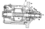
제1도는 제1의 발명의 일실시예에 관한 관성 슬라이딩식의 시동 전동기를 나타내는 단면도.1 is a cross-sectional view showing an inertial sliding start motor according to an embodiment of the first invention.
제2도는 제2의 발명의 일실시예에 관한 관성 슬라이딩식의 시동 전동기를 나타내는 도면.2 is a view showing an inertial sliding start motor according to an embodiment of the second invention.
제3도는 제2발명의 다른 실시예를 나타내는 단면도.3 is a cross-sectional view showing another embodiment of the second invention.
제4도는 제3의 발명의 일실시예에 관한 관성 슬라이딩식의 시동 전동기를 나타내는 단면도.4 is a cross-sectional view showing an inertial sliding start motor according to an embodiment of the third invention.
제5도는 제3발명의 다른 실시예를 나타내는 단면도.5 is a cross-sectional view showing another embodiment of the third invention.
제6도는 종래의 관성 슬라이딩식 시동 전동기를 나타내는 단면도.6 is a cross-sectional view showing a conventional inertial sliding start motor.
제7도는 종래의 관성 슬라이딩식 시동 전동기를 나타내는 단면도.7 is a cross-sectional view showing a conventional inertial sliding start motor.
* 도면의 주요부분에 대한 부후의 설명* Explanation of the minor parts of the drawings
20 : 시동 전동기 21 : 전동기20: starting motor 21: electric motor
22 : 프론트 하우징 23 : 지지축22: front housing 23: support shaft
24 : 오버런닝 클러치 24a : 클러치 외측 부재24: overrunning clutch 24a: clutch outer member
24b : 클러치 내측 부재 27 : 클러치 지지체24b: clutch inner member 27: clutch support
29 : 헬리컬 스플라인 30 : 피니온 이동체29: helical spline 30: pinion moving body
30a : 통상부 30b : 치부30a: normal part 30b: tooth part
30c : 피니온 30d : 플랜지30c: Pinion 30d: Flange
34a : 먼지막이 방수 커버34a: dust cover waterproof cover
본 발명은 시동 전동기에 관한 것으로, 좀더 상세하게는 전동기에 의한 피니온의 회전시 그 관성에 의하여 축상을 슬라이딩(sliding)하는 관성 슬라이딩 시동 전도기에 관한다.BACKGROUND OF THE
종래, 이런 종류의 관성 슬라이딩식 시동 전동기는 실개소 56-107957호 공보에 개시되어 있다. 해당 공보에 개시되어 있는 종래의 관성 슬라이딩식 시동 전동기(이하 간단히 ″시동 전동기″라 한다)는 제6도에 도시된 바와 같이, 전동기(1)에서 연장하는 전기자 회전축(2)의 베어링부(3)에 슬라이딩 가능하게 장착된 오버런닝 클러치 (4) 및 리니온(5)을 갖추고, 이 오버런닝 클러치(4)의 츨러치 외측 부재( 4a)는 그 보스부 내주면에 형성된 치부가 축부(3)에 형성된 헬리컬 스플라인(6)에 치합하고, 피니온(5)은 클러치 내측 부재(4b)와 일체로 형성되며, 그 내주면에 장착된 슬리브 베어링 (7)에 의하여 축부(3)상에서 슬라이드할 수 있도록 지지되고, 또한 전기자 회전축은 프론트 하우징(15)에 장착된 베어링(14)에 의하여 지지되어 구성되어 있다.Conventionally, an inertial sliding start motor of this kind is disclosed in Japanese Patent Application Laid-Open No. 56-107957. The conventional inertial sliding start motor (hereinafter simply referred to as "starting motor") disclosed in this publication is a bearing portion 3 of the armature rotating shaft 2 extending from the
또한, 제6도에서, 8은 기관의 링기어, 9는 축부(3)의 단부에 고정된 스토퍼, 10은 스터퍼(9)와 피니온(5)사이에 배치된 리턴 스프링(return spring), M은 전동기(1)에 급전하는 급전 단자를 각각 나타내고 있다.Also in FIG. 6, 8 is a ring gear of the engine, 9 is a stopper fixed to the end of the shaft portion 3, 10 is a return spring disposed between the stuffer 9 and the pinion 5. , M represent power feeding terminals for feeding the
다음에 이러한 종래의 시동 전동기 동작을 간단하게 설명한다.Next, such a conventional starting motor operation will be briefly described.
제7도에 도시된 회로도를 참조하여, 차량의 키 스위치(11)로 폐로(閉路)하면, 밧데리(12)에서 전자 스위치(13)의 스위치 코일(13a)에 전류가 흐르고, 전자 스위치 (13)의 플런저(13b)가 흡인되어 가동 접점(13c)을 고정 접점(13d,13e)에 당접시키고, 이것에 의하여 상기 개방 접점이 폐로한다. 그결과, 전동기(1)의 급전 단자(M)에 밧데리(12)의 전압이 인가되며, 계자 코일(1a)과 전기자(1b)의 코일에 전류가 흘러 전기자(1b)가 회전한다. 이때, 오버런닝 클러치(4) 및 이것과 일체인 피니온(5)은 축부(3)에 형성된 헬리컬 스플라인(6)의 경사각과 해당 오버런닝 클러치(4)등의 관성에 의하여 리턴 스프링(10)에 저항하여 전방(제6도에서 보아 우측)으로 슬라이딩 하고, 피니온(5)이 링기어(8)와 치합(齒合)하여 기관을 시동한다. 키 스위치(11)를 개방하면 상기 설명과는 역으로 가동접점(13c)이 접점 스프링(도시되지 않음)에 의하여 고정 접점 (13d,13e)에서 복귀하여 전동기(1)로의 급전을 종료함과 동시에 오버런닝 클러치(4)와 함께 피나온(5)은 리턴 스프링(10)의 압축력에 의하여 제6도의 정지 위치로 복귀된다.Referring to the circuit diagram shown in FIG. 7, when the vehicle is closed by the key switch 11 of the vehicle, current flows from the battery 12 to the switch coil 13a of the electronic switch 13 and the electronic switch 13. ), The plunger 13b is aspirated to abut the movable contact 13c to the fixed contacts 13d and 13e, thereby closing the open contact. As a result, the voltage of the battery 12 is applied to the power supply terminal M of the
상기와 같이 구성된 시동 전동기에서는 아래의 관계가 있었다.In the starting motor configured as described above, the following relations existed.
(a) 피니온(5)이 오버런닝 클러치(4)의 클러치 내측 부재(4b)와 일체로 형성되어 있으므로, 기관을 시동시킬 때, 오버런닝 클러치(4)와 피니온(5)이 함께 이동한다. 따라서, 피니온(5)의 링기어(8)와의 치합 초기에 충격력이 커서, 피니온(5) 또는 링기어(8)를 파손시킬 염려가 있었다.(a) Since the pinion 5 is formed integrally with the clutch inner member 4b of the overrunning clutch 4, when the engine is started, the overrunning clutch 4 and the pinion 5 move together. do. Therefore, the impact force was large at the initial stage of engagement of the pinion 5 with the ring gear 8, and there was a risk of damaging the pinion 5 or the ring gear 8.
(b) 피니온(5)과 프론트 하우징(15)에 장착된 베어링(14)과의 사이가 길기 때문에 전기자 회전축(2)이 캔틸레버 구성으로 되어 큰 굽힘 모멘트가 생겨서 전기자 회전축이 굽거나 절손(折損)하는 것도 있었다.(b) Since the pinion 5 and the bearing 14 mounted on the front housing 15 are long, the armature rotating shaft 2 has a cantilever configuration, resulting in a large bending moment, causing the armature rotating shaft to bend or bend. There was also).
(c) 피니온(5)과 그 슬라이딩부가 노출하고, 화살표 방향에서 시동 전동기에 물이 덮치면 축부(3)에 녹이발생(發생)하여 피니온(5)의 슬라이딩을 불량하게 하거나, 리턴 스프링(10)이 녹슬어서 절손되기도 한다. 또한 오버런닝 클러치의 내측 부재(4a)와 프론트 하우징(15) 사이의 틈새로 침입한 물은 전기자 회전축(2)을 지지하는 베어링(14)과 그 전기자 회전축(2)의 틈새를 통하여 전동기내에 달하고, 이 결과 전동기의 동작 불량을 초래한다는 문제가 있었다. 이러한 상태는, 예를들면, 선외기관(船外機關)이나 산업 기관과 같이 크랭크 샤프트가 수직으로 설치되고, 플라이 휘일이 수평으로 장치되어 있으며, 시동 전동기가 피니온을 위로하여 종방향으로 장치되는 경우에 특히 발생하기 쉽다.(c) If the pinion 5 and its sliding part are exposed, and water is applied to the starting motor in the direction of the arrow, rust will occur in the shaft part 3, resulting in poor sliding of the pinion 5, or return. The spring 10 may be rusted and broken. In addition, the water penetrating into the gap between the inner member 4a of the overrunning clutch and the front housing 15 reaches the electric motor through the gap between the bearing 14 supporting the armature rotating shaft 2 and the armature rotating shaft 2. As a result, there has been a problem that it causes a malfunction of the motor. In this state, for example, the crankshaft is vertically installed, the flywheel is horizontally installed, and the starting motor is installed in the longitudinal direction with the pinion upwards, such as an outboard engine or an industrial engine. It is especially prone to occur.
본 발명의 목적은 이러한 종래의 문제점을 해결하기 위한 것으로, 기관의 링기어에 피니온이 치합하는 초기의 충격력을 작게하여 피니온이나 링기어의 손상 방지를 함과 동시에 물이 덮침으로써 전기자 회전축 선단부에 녹이 발생하는 것을 방지하고, 피니온의 녹발생에 의한 슬라이딩 불량을 방지하며, 전동기내로의 침수에 의한 동작 불량을 회피할 수 있는 관성 슬라이딩형의 시동 전동기를 얻는 것을 목적으로 한다.An object of the present invention is to solve such a conventional problem, to reduce the initial impact force of the pinion to the ring gear of the engine to prevent damage to the pinion or ring gear and to cover the water at the same time the tip of the armature rotating shaft An object of the present invention is to obtain an inertial sliding type starter motor which can prevent rust from occurring, prevent sliding failure due to rust generation of pinion, and avoid operation failure due to immersion into the motor.
제1발명에 관한 시동 전동기는, 전기자 회전축과 일체로 회전하는 오버런닝 클러치의 외측 부재와 로터를 개재하여 결합된 오버런닝 클러치의 내측 부재가 프론트 하우징에 장착된 베어링에 전방 방향으로 이동불능하게 지지되며, 상기 내측 부재의 내주 (內周)에 피니온과 계합하는 헬리컬 스플라인을 설치하고, 피니온은 상기 전기자 회전축에 전후방향으로 슬라이딩 가능하게 지지되며, 헬리컬 스플라인에 의하여 내측 부재로부터 피니온에 회전력이 부여되도록 한 것이고, 또한, 제2발명은 상기 시동 전동기의 피니온 후방부에 플랜지를 설치하고, 이 플랜지의 외경을 프론트 하우징의 전방 단부의 개구 구경보다 크게 한 것이며, 제3발명은 상기 시동 전동기의 내측 부재 전단부와 피니온의 후단면은 상기 피니온이 기관의 링 거어에 비계합상태에 있을 때 맞닿고, 피니온 전단부의 전기가 회전측부를 커버로서 덮도록 한 것이다.The starting motor according to the first aspect of the invention has an outer member of the overrunning clutch which rotates integrally with the armature rotating shaft and an inner member of the overrunning clutch coupled via the rotor incapable of moving forwardly in a bearing mounted on the front housing. And a helical spline engaging with the pinion on an inner circumference of the inner member, the pinion being slidably supported in the front-rear direction on the armature rotational axis, and the rotational force from the inner member to the pinion by the helical spline. In the second invention, a flange is provided at the rear of the pinion of the starting motor, and the outer diameter of the flange is made larger than the opening diameter of the front end of the front housing. The front end of the inner member of the electric motor and the rear end of the pinion should be connected to the ringer of the engine. Abuts when, to one so that the front end of the pinion cover the electric rotating side as the cover.
본 발명의 시동 전동기에 의하면, 전동기가 구동되면, 그 구동력을 받아 일방향 클러치 장치의 클러치 외측 부재에 회전력이 부여되며, 로울러를 거쳐 클러치 내측 부재에 회전력이 부여된다. 이때, 피니온 이동체는 클러치 내측 부재의 내주부에 형성된 헬리컬 스플라인의 경사각과 그 피니온 이동체의 관성에 의하여 지지축상을 슬라이딩하고, 피니온이 링 기어에 치합하여 기관을 시동시킨다.According to the starting motor of the present invention, when the electric motor is driven, the driving force is applied to the clutch outer member of the one-way clutch device, and the rotational force is applied to the clutch inner member via the roller. At this time, the pinion moving body slides on the support shaft by the inclination angle of the helical spline formed on the inner circumference of the clutch inner member and the inertia of the pinion moving body, and the pinion engages with the ring gear to start the engine.
또한, 피니온에 설치한 플랜지가 프론트 하우징과 오버러닝 클러치의 외측 부재의 틈새를 덮는 외경으로 되어 있으므로, 시동 전동기로 물이 덮친 경우 물은 플랜지의 바깥주위로 흘러 외부로 배수된다. 이것에 의하여 전동기내로의 물의 침입을 방지할 수 있다.In addition, since the flange provided on the pinion has an outer diameter covering the gap between the front housing and the outer member of the overrunning clutch, when water is covered by the starting motor, the water flows to the outer periphery of the flange and is drained to the outside. This can prevent water from entering the motor.
또한, 피니온이 오버런닝 클러치의 내측 부재 내면의 헬리컬 스플라인과 계합하여 전기자 회전축을 따라 슬라이딩 하도록 하였으므로, 피니온이 기관의 링기어와 비계합 상태에서 상기 피니온의 후단면을 내측 부재의 전단부에 맞닿게 할 수 있으며, 이것에 의하여 전동기는 외부와의 틈새를 없게하여, 물의 덮침에 의한 물의 침입을 방지할 수 있다. 피니온 전단부의 전기자 회전축 부분을 커버로서 덮도록 하였으므로, 회전축에 녹이 발생하지 않도록 하여 슬라이딩 불량을 방지할 수 있다.In addition, since the pinion engages with the helical spline on the inner surface of the inner member of the overrunning clutch, the pinion slides along the armature rotation axis. In this way, the electric motor can be prevented from infiltrating with the outside, thereby preventing the ingress of water by the covering of the water. Since the armature rotation shaft portion of the pinion front end portion is covered as a cover, rust does not occur on the rotation shaft, and sliding failure can be prevented.
이하 본 발명의 관성 슬라이딩식 시동 전동기를 첨부 도면과 관련하여 더욱 상세히 설명한다.Hereinafter, the inertial sliding start motor of the present invention will be described in more detail with reference to the accompanying drawings.
제1도는 제1발명의 한 실시예에 관한 관성 슬라이딩식 시동 전동기(20)가 도시되어 있다. 본 실시예의 시동 전동기(20)는 계자 코일(21a) 및 전기자(21b)를 갖춘 전동기부(21)를 구비하고, 그 전기자 회전축(21c)은 프론트 하우징(22)를 거쳐서 전방(제1도에서 보아 우방향)으로 연장하여 그 회전축(21c)과 일체인 지지축(23)을 구성하고 있다.1 shows an inertial
프론트 하우징(22)의 내축에서 지지추거(23)상에는 오버런닝 클러치(24)가 동심적으로 배치되어 있다. 이 오버런닝 클러치(24)에 있어서 클러치 외측 부재(24 a)의 보스부는 전기자(21b)에 인접하는 위치에서 전기자 회전축(21c)에 설치된 스트레이트 스플라인(25 ; straight spline)에 치합하고, 클러치 내측 부재(24b)와 지지축(23)사이에 베어링(26)이 배치되어 있다. 이 클러치 내측 부재(24b)이 전단으로부터 일체적으로 통상(筒牀)의 클러치 지지체(27)가 축방향 전방으로 돌출하고, 그 클러치 지지체(27)는 프론트 하우징(22)에 장착된 베어링(28)의 내측 레이스에 삽입 장착되어 있다. 이 클러치 지지체(27)의 외주부에는 그 전체 또는 일부에 베어링(28)에 내측 레이스 측면에 맞닿는 지름방향 돌출부(27a)가 설치되어, 이 돌출부(27a)와 베어링 (28)과의 맞닿음 및 클러치 외측 부재(24a)의 보스부 후단부와 지지축 단부의 맞닿음에 의하여 오버런닝 클러치(24)를 전후방향, 즉, 횡방향으로 이동 불능하게 지지하고 있다.The overrunning
클러치 내측 부재(24b)와 이것에 일체인 클러치 지지체(27)의 내주부에 있는 축방향 연속면에서는 헬리컬 스플라인(29)이 형성되며, 이 헬리컬 스플라인(29)에는 클러치 내측 부재(24b)의 내주부에 삽입된 피니온 이동체(30)의 통상부(30a ; 筒狀部)의 후단 외주면에 형성된 치부(30b)가 치합하고 있다. 이 피니온 이동체(30 )의 내주부에는 슬리브 베어링(31)이 장착되며, 이것에 의하여 피니온 이동체(30)는 지지축 (23)상을 슬라이딩 및 회전 가능하게 지지도어 있다. 피니온 이동체(30)를 구성하는 피니온(30c)은 통상부(30a)의 전단부에 일체적으로 형성되며, 프론트 하우징(22)의 외측에 위치한다.A
또한 제1도에서, 32는 지지축(23)의 전단부에 장치된 스토퍼, 33은 이 스토퍼 (32)와 피니온 통상부(30a) 내주면의 넓은 직경은 단부 사이에 배치된 리턴 스프링, 34는 피니온 통상부(30a)의 전단면에 장착되며, 피니온(30c)에서 전방으로 돌출한 지지축(23)의 단부를 포위하는 캡, 35는 프론트 하우징(22)의 개구부와 클러치 지지체 (27)의 외주부 사이에 배치된 오일 시일을 각각 나타내고 있다.Also in FIG. 1, 32 is a stopper provided at the front end of the support shaft 23, 33 is a large diameter of the stopper 32 and the inner circumferential surface of the pinion normal part 30a, and the return spring is disposed between the ends. A cap attached to the front end surface of the pinion ordinary portion 30a and surrounding the end of the support shaft 23 protruding forward from the
다음에, 상술의 실시예에 있어서 시동 전동기(20)의 동작을 설명한다. 급전 단자(M)까지의 회로 구성 및 전자 스위치 장치의 작동에 대하여는 제7도에 나타낸 종래예와 같으므로 그 설명을 생략한다.Next, the operation of the starting
급전 단자(M)에 밧테리의 전압이 인가되면, 계자 코일(21a)과 전기자(21b) 코일에 전류가 흘러 전기자(21b)가 회전하기 시작한다. 이것에 의한 전기자 회전축(21c)의 회전은 스트레이트 스플라인(25)을 거쳐일방향 크러치 장치(24)의 클러치 외측 부재(24a)에 전달되고 로울러(24c)를 거쳐 클러치 내측 부재(24b)에 전달된다. 클러치 내측 부재(24b)에 회전력이 부여되면, 그 내주면에 형성된 헬리컬 스플라인(29)의 경사각과 피니온 이도체(30)의 관성에 의하여 피니온 이동체(30 )가 리턴 스프링(33)에 대항하여 전방으로 지지축(23)상을 슬라이딩 이동하고, 피니온(30c)이 기관의 링 기어와 치합하여 이것을 회전시키고, 기관을 시동한다. 기관이 시동한후, 키 스위치를 끊으면 피니온 이동체(30)는 리턴 스프링(33)의 복귀력에 의하여 원래의 위치(제1도에 나타내는 위치)로 복귀한다.When the voltage of the battery is applied to the power supply terminal M, current flows through the field coil 21a and the armature 21b coil and the armature 21b starts to rotate. The rotation of the
이와같이, 상술의 실시예에서는 피니온 이동체(30)만을 지지축(23)상에서 슬라이딩 가능하게 하고 오버런닝 클러치(24)는 횡방향으로 움직일 수 없도록 함으로써 피니온(30c)과 링 기어의 치합 초기의 충격력을 매우 작게할 수 있고, 그 때문에 피니온 (30c)이나 링 기어의 손상을 방지할 수 있다.As described above, in the above-described embodiment, only the pinion moving body 30 is slidable on the support shaft 23 and the overrunning
본 실시예에서는 오버런닝 클러치(24)가 클러치 지지체(27)에 의하여 실질적으로 베어링(28)을 거쳐 프론트 하우징(22)에 지지되어 있으므로, 그 하중의 지지축 (23)에 직접 걸리지 않고, 더구나 피니온(30c)의 위치와 지지축(23)을 수용한 베어링 (26)의 위치 사이의 거리가 제6도에 나타낸 종래예에 비하여 짧게 할 수 있으므로, 지지축(23)이 굽힘 모멘트가 현저하게 적어지며, 지지축의 구부러짐이나 절손 발생을 방지할 수 있다.In this embodiment, since the overrunning
또한 본 실시예에서는 오버런닝 클러치(24)를 프론트 하우징(22)의 내측에 배치하고, 오버런닝 클러치(24)를 지지하는 클러치 지지체(27)의 외주면과 프론트 하우징(22) 사이에 배치된 베러일(28) 및 베어링(28)에 인접하여 축방향 전방축에 배치된 오일 시일(35)에 의하여 프론트 하우징(22) 내부로 물 또는 먼지가 진입하는 것을 방지하고 있으므로, 오버런닝 클러치의 작동 불량을 방지할 수 있고 또한 전동기(21)의 각부에 녹이 발생하는 것을 방지할 수 있다.In addition, in the present embodiment, the overrunning
다음에 제2발명의 한 실시예를 제2도에 의하여 설명한다. 또한 급전 단자까지의 회로 구성 및 전자 스위치 장치의 작동에 대하여 설명을 생략한 것은 제1도와 같다.Next, an embodiment of the second invention will be described with reference to FIG. In addition, it abbreviate | omits description about the circuit structure and the operation | movement of an electronic switch apparatus to a feed terminal.
30d는 피니온(30c)의 후방부에 지름방향으로 돌출된 플랜지로서, 이 플랜지 (30d)의 외경(D)은 프론트 하우징(22)의 전방 단부의 개구 구경(d)보다 크게하고 있다. 플랜지(30d)가 오버런닝 클러치 장치의 클러치 지지체(27)와 프론트 하우징(22) 사이의 틈새를 덮고 있다.30d is a flange projecting radially in the rear part of the
특히 본 발명에 의한 시동 전동기는 피니온(30c)에 설치한 플랜지(30d)가 오버런닝 클러치 장치의 클러치 지지체(27)와 프론트 하우징(22) 사이의 틈새를 덮고 있으므로, 시동 전동기의 위쪽이 물에 잠겼다하더라도 물은 플랜지(30d)의 바깥 주위를 흘러 프론트 하우징(22)의 측면을 따라 외부로 배수할 수 있으므로, 물의 일부가 상기 클러치 지지체(27)와 프론트 하우징(22) 사이의 틈새로 침입하여 전동기내로 유입할 수 없다.In particular, the starting motor according to the present invention covers the gap between the
또한, 피니온(30c)에 설치한 플랜지(30d)는 다른 예로서 제3도에 나타나듯이 플랜지(30d)의 외주부를 프론트 하우징(22)측으로 굴곡되게 형성하도록 하여도 좋은데, 이와같이 하면 상기 틈새로 물이 침입하는 것을 확실하게 방지할 수 있다.In addition, the
다음에 제3발명의 한 실시예를 제4도에 의하여 설명한다.Next, an embodiment of the third invention will be described with reference to FIG.
우선 34a는 방수용 커버로서, 피니온(30c)의 전단부의 지지축(23)부분, 리턴 스프링(33) 및 스토퍼(32)를 덮고 있다. 또한 35는 베어링(28)의 전측면에 접하여 프론트 하우징(22)에 장착되며, 클러치 지지체(27)의 외주면에 접하게 장착된 오일 시일이다. 그리고, 피니온(30c)이 기관의 링 기어와 비계합 상태에서는 그 피니온( 30c)의 후단면이 클러치 지지체(27)의 전단부와 맞닿고 있다. 그결과 시동 전동기는 외부의 틈새를 없도록 할 수 있으며, 이것에 의하여 관수에 의한 전동기 내로의 물침입을 방지할 수 있다.First, 34a is a waterproof cover and covers the support shaft 23 part, the return spring 33, and the stopper 32 of the front end of the
또한 피니온(30c)의 전단부 지지축 부분을 커버(34a)로서 덮도록 하였으므로 관수에 의한 지지축(23)이나 리턴 스프링(33)에 녹이 발생하지 않으며, 따라서 피니온 (30c)이 슬라이딩을 항시 원활하게 행할 수 있다.In addition, since the front support shaft portion of the
또한 상술의 제1발명의 실시예는 클러치 외측 부재(24a)를 전기자 회전축(21 c)의 단부에 형성된 스트레이트 스플라인(25)에 결합한 것이었지만, 일체로 구성하여도 또 키(key)로 고정하거나 혹은 나사로 고정해도 좋다. 필요한 경우 클러치 외측 부재 (24a)에 전기자 회전축(21c)의 회전이 전달되는 구성이어도 좋다.In addition, although the embodiment of the first invention described above is coupled to the straight spline 25 formed at the end of the
또한 제3발명의 실시예에서는 베어링(28)의 전측면에 접하여 오일 시일(35)을 갖춘 예에 대하여 나타냈지만, 제5도에 나타낸 종(從)형식과 같이 피니온 후단부 외경(d)이 클러치 지지체(27)의 베어링(28)의 외경(B)보다 크고, 프론트 하우징(22)의 전단부 개구 구경(D)이 피니온(30c)의 후단부 외경(d)보다 작으면, 물이 베어링 (28)측으로 침입하지 않으므로, 이러한 기구의 상기 오일 시일(35)은 필요없게 된다. 또한, 베어링(28)은 클러치 지지체(27)의 맞닿은 면의 틈새를 영에 가깝게 하는 것이 바람직함으로 슬리브 베어링보다 볼 베어링이 좋고, 상기 오일 시일이 없는 경우는 볼 베어링을 시일 부착 구조로 하는 방법이 좋다. 또한 클러치 지지체(27)나 볼 베어링등을 스텐레스계로 하면 방청 효과를 향상시킬 수 있다.In addition, in the embodiment of the third invention, the oil seal 35 is shown in contact with the front side of the
또한 제1 내지 제3발명의 실시예에 있어서 전동기(21)는 자계 발생 수단으로서 계자 코일(21a)을 사용했지만, 이 경우 자석이어도 좋다.In the first to third embodiments, the
이상 설명했듯이, 제1발명에 의하면, 전기자 회전축과 일체로 회전하는 오버런닝 클러치의 외측 부재와, 로울러를 개재하여 결합된 오버런닝 클러치의 내측 부재가 프론트 하우징에 장착된 베어링에 전방 방향으로 이동 불능하게 지지되며, 상기 내측 부재의 내주면에 피니온과 계합하는 헬리컬 스플라인을 설치하고, 피니온을 상기 전기자 회전축에 전후 방향으로 슬라이딩 지지되며, 헬리컬 스플라인에 의하여 내측 부재에서 피니온으로 회전력이 부여되도록 구성했으므로, 피니온과 링기어에 있어서의 치합 초기의 충격력을 매우 작게 할 수 있고, 그 결과 피니온이나 링 기어의 지지축 손상을 방지할 수 있다.As described above, according to the first invention, the outer member of the overrunning clutch that rotates integrally with the armature rotational shaft and the inner member of the overrunning clutch coupled via the rollers cannot move forward in the bearing mounted on the front housing. And a helical spline engaged with the pinion on the inner circumferential surface of the inner member, and the pinion is slidably supported in the front and rear direction on the armature rotation axis, and is configured to impart rotational force from the inner member to the pinion by the helical spline. Therefore, the impact force at the initial stage of engagement between the pinion and the ring gear can be made very small, and as a result, damage to the support shaft of the pinion and the ring gear can be prevented.
또한 제2발명에 의하면, 피니온의 후방부에 플랜지를 설치하고, 그 플랜지의 외경을 상기 프론트 하우징의 전방 단부의 개구 구경보다 크게 구성했으므로, 외부에서 시동 전동기로 물이 덮치더라도 상기 틈새로 물이 침입하지 않으며, 이것에 의하여 물의 침입에 의한 전동기부의 고장을 미연에 방지하고, 신뢰성이 높은 시동 전동기로 된다.According to the second aspect of the present invention, a flange is provided on the rear portion of the pinion, and the outer diameter of the flange is larger than the opening diameter of the front end of the front housing. Therefore, even if water is covered by the starting motor from the outside, This does not penetrate, thereby preventing the failure of the electric motor unit due to the intrusion of water, and thus, the motor becomes a highly reliable starting motor.
또한 제3발명에 의하면, 내측 부재의 전단부와 피니온의 후단면은 상기 피니온이 기관의 링 기어와 비계합 상태에서 맞닿고, 피니온 잔단부의 전기자 회전축부가 커버를 덮도록 구성하였으므로, 시동 전동기는 외부와의 틈새를 없게 할 수 있고, 이결과 물에 잠김으로써 전동기내로 물이 침입하는 것을 방지하여, 그 전동기의 동작 불량을 미연에 방지할 수 있다. 또한 피니온 전단부의 지지축 부분을 커버로서 덮도록 하였으므로, 물에 잠김에 의한 지지축이나 리턴 스프링의 녹발생도 없고, 따라서 피니온의 슬라이딩을 항상 원활하게 행하며, 신뢰성이 높은 시동 전동기로 된다.According to the third invention, the front end portion of the inner member and the rear end surface of the pinion are configured such that the pinion abuts in a non-engaged state with the ring gear of the engine, and the armature rotating shaft portion of the pinion residual portion covers the cover. The starting motor can be free from a gap with the outside, and as a result, the water can be prevented from invading the motor by being submerged in water, thereby preventing the malfunction of the motor in advance. In addition, since the support shaft portion of the pinion front end portion is covered as a cover, there is no rust of the support shaft or the return spring caused by the submersion, so that the pinion slides smoothly all the time, thereby providing a reliable starting motor.
Claims (3)
Applications Claiming Priority (9)
| Application Number | Priority Date | Filing Date | Title |
|---|---|---|---|
| JP63-237110 | 1988-09-21 | ||
| JP63237110A JP2515863B2 (en) | 1988-09-21 | 1988-09-21 | Starter motor |
| JP??63-237110 | 1988-09-21 | ||
| JP1988126663U JPH0250071U (en) | 1988-09-27 | 1988-09-27 | |
| JP63-126662 | 1988-09-27 | ||
| JP??63-126662(U) | 1988-09-27 | ||
| JP1988126662U JPH0250070U (en) | 1988-09-27 | 1988-09-27 | |
| JP??63-126663(U) | 1988-09-27 | ||
| JP63-126663 | 1988-09-27 |
Publications (2)
| Publication Number | Publication Date |
|---|---|
| KR900005062A KR900005062A (en) | 1990-04-13 |
| KR930000475B1 true KR930000475B1 (en) | 1993-01-21 |
Family
ID=27315378
Family Applications (1)
| Application Number | Title | Priority Date | Filing Date |
|---|---|---|---|
| KR1019890013412A KR930000475B1 (en) | 1988-09-21 | 1989-09-19 | Engine startermotor |
Country Status (3)
| Country | Link |
|---|---|
| US (1) | US5014563A (en) |
| KR (1) | KR930000475B1 (en) |
| DE (1) | DE3931256A1 (en) |
Families Citing this family (15)
| Publication number | Priority date | Publication date | Assignee | Title |
|---|---|---|---|---|
| US5945755A (en) * | 1994-09-20 | 1999-08-31 | Denso Corporation | Starter with housing for cantilever-mounting on engine |
| JP3241282B2 (en) * | 1996-12-06 | 2001-12-25 | 株式会社日立製作所 | Automotive starter motor and automotive starter |
| US6109122A (en) * | 1998-11-10 | 2000-08-29 | Delco Remy International, Inc. | Starter motor assembly |
| JP2001065436A (en) * | 1999-08-27 | 2001-03-16 | Hitachi Ltd | Starter |
| JP2002180936A (en) * | 2000-12-08 | 2002-06-26 | Denso Corp | Starter |
| US6630760B2 (en) | 2001-12-05 | 2003-10-07 | Delco Remy America, Inc. | Coaxial starter motor assembly having a return spring spaced from the pinion shaft |
| US6633099B2 (en) | 2001-12-05 | 2003-10-14 | Delco Remy America, Inc. | Engagement and disengagement mechanism for a coaxial starter motor assembly |
| JP4124091B2 (en) * | 2003-10-16 | 2008-07-23 | 株式会社デンソー | Starter |
| FR2865243B1 (en) * | 2004-01-16 | 2009-06-26 | Denso Corp | STARTER WITH LIMITATION OF VIBRATION AND INCLINATION OF OUTPUT TREE |
| US20060117876A1 (en) * | 2004-12-07 | 2006-06-08 | Remy International, Inc. | Sealed and oil lubricated starter motor gear reduction and overrunning clutch mechanism |
| DE102007059119A1 (en) * | 2007-12-07 | 2009-06-10 | Robert Bosch Gmbh | machine tool |
| DE102008040106A1 (en) * | 2008-07-03 | 2010-01-07 | Robert Bosch Gmbh | Starter for an internal combustion engine |
| JP2013083176A (en) * | 2011-10-07 | 2013-05-09 | Denso Corp | Starter |
| CN105626344B (en) | 2014-10-27 | 2019-10-18 | 法雷奥电机设备公司 | Motor vehicles combustion engine starter with air ventilation holes |
| US10389208B2 (en) * | 2016-03-09 | 2019-08-20 | Johnson Controls Technology Company | HVAC actuator with one-way clutch motor |
Family Cites Families (18)
| Publication number | Priority date | Publication date | Assignee | Title |
|---|---|---|---|---|
| DE575718C (en) * | 1933-05-02 | Gottlieb Steiner | Coupling that acts in one sense of rotation and is subject to impact | |
| US2084813A (en) * | 1931-08-06 | 1937-06-22 | Eclipse Aviat Corp | Engine starting mechanism |
| DE596411C (en) * | 1931-10-25 | 1934-05-02 | Gottlieb Steiner | Pinion starter |
| DE844691C (en) * | 1946-06-22 | 1952-07-24 | Scintilla Ag | Electric starting device for internal combustion engines |
| US2924979A (en) * | 1955-11-10 | 1960-02-16 | Gen Electric | Starter jaw advancing mechanism |
| GB1147193A (en) * | 1965-10-22 | 1969-04-02 | Cav Ltd | Starting mechanism for internal combustion engines |
| US3630092A (en) * | 1969-01-23 | 1971-12-28 | Mitsubishi Electric Corp | Starter for internal-combustion engine |
| US3656355A (en) * | 1969-03-28 | 1972-04-18 | Mitsubishi Electric Corp | Engine starter having means for holding same in a cranking position |
| US3690188A (en) * | 1970-05-07 | 1972-09-12 | Ambac Ind | Engine starter drive assembly |
| JPS54138926A (en) * | 1978-04-19 | 1979-10-27 | Hitachi Ltd | Starter |
| JPS56107957A (en) * | 1980-01-31 | 1981-08-27 | Hitachi Ltd | Fuel pulverizer |
| US4347442A (en) * | 1980-07-14 | 1982-08-31 | Eaton Stamping Company | Double insulated starter motor |
| JPS59141768A (en) * | 1983-02-02 | 1984-08-14 | Nippon Denso Co Ltd | Inertia plunging type starter motor |
| JPS6069574U (en) * | 1983-10-18 | 1985-05-17 | 三菱電機株式会社 | starter dynamo |
| JPS62195455A (en) * | 1986-02-20 | 1987-08-28 | Nippon Denso Co Ltd | Starter |
| JPS63209448A (en) * | 1987-02-23 | 1988-08-31 | Mitsubishi Electric Corp | Starter for engine |
| JPS63134171U (en) * | 1987-02-25 | 1988-09-02 | ||
| DE3885535T2 (en) * | 1987-08-07 | 1994-04-28 | Mitsubishi Electric Corp | Electric starter motor. |
-
1989
- 1989-09-19 KR KR1019890013412A patent/KR930000475B1/en not_active IP Right Cessation
- 1989-09-19 DE DE3931256A patent/DE3931256A1/en active Granted
- 1989-09-21 US US07/410,569 patent/US5014563A/en not_active Expired - Lifetime
Also Published As
| Publication number | Publication date |
|---|---|
| US5014563A (en) | 1991-05-14 |
| KR900005062A (en) | 1990-04-13 |
| DE3931256A1 (en) | 1990-03-29 |
| DE3931256C2 (en) | 1993-02-18 |
Similar Documents
| Publication | Publication Date | Title |
|---|---|---|
| KR930000475B1 (en) | Engine startermotor | |
| US5443553A (en) | Starter | |
| KR940002670B1 (en) | Electromagnetic switch apparatus and starter | |
| US4974463A (en) | Starting motor with a translatable idler/pinion gear | |
| US3772921A (en) | Engine starter | |
| US7647849B2 (en) | Starter with intermediate gear | |
| US4695735A (en) | Engine starter drive with integral starter relay | |
| KR880009194A (en) | Engine starter | |
| KR950009045B1 (en) | Intermediate gear type starter | |
| JP4785845B2 (en) | Starter | |
| EP0702150B1 (en) | Starter | |
| KR950007104Y1 (en) | Stanting moter sealing apparatus with intermediate gear | |
| KR100636080B1 (en) | A starter for an engine | |
| KR930003261Y1 (en) | Inertia drive engine starter | |
| KR930000322Y1 (en) | Starter motor | |
| US20020157489A1 (en) | Starter motor having seal member for sealing axial end of housing | |
| US6789520B2 (en) | System for cranking internal combustion engine | |
| KR910008703B1 (en) | Starting motor | |
| US20040134294A1 (en) | Starter | |
| US4931663A (en) | Starter motor | |
| KR920000383Y1 (en) | Start motor | |
| KR910000048Y1 (en) | Startor | |
| EP0725216B2 (en) | Starter | |
| JPH0119067B2 (en) | ||
| JPS6216759Y2 (en) |
Legal Events
| Date | Code | Title | Description |
|---|---|---|---|
| A201 | Request for examination | ||
| E902 | Notification of reason for refusal | ||
| G160 | Decision to publish patent application | ||
| E701 | Decision to grant or registration of patent right | ||
| GRNT | Written decision to grant | ||
| FPAY | Annual fee payment |
Payment date: 20060110 Year of fee payment: 14 |
|
| LAPS | Lapse due to unpaid annual fee |