KR920004638B1 - Method for combined baking-out and panel-sealing of a partilly-assembled crt - Google Patents
Method for combined baking-out and panel-sealing of a partilly-assembled crt Download PDFInfo
- Publication number
- KR920004638B1 KR920004638B1 KR1019840000189A KR840000189A KR920004638B1 KR 920004638 B1 KR920004638 B1 KR 920004638B1 KR 1019840000189 A KR1019840000189 A KR 1019840000189A KR 840000189 A KR840000189 A KR 840000189A KR 920004638 B1 KR920004638 B1 KR 920004638B1
- Authority
- KR
- South Korea
- Prior art keywords
- sealing
- panel
- neck
- funnel
- ray tube
- Prior art date
Links
Images


Classifications
-
- H—ELECTRICITY
- H01—ELECTRIC ELEMENTS
- H01J—ELECTRIC DISCHARGE TUBES OR DISCHARGE LAMPS
- H01J9/00—Apparatus or processes specially adapted for the manufacture, installation, removal, maintenance of electric discharge tubes, discharge lamps, or parts thereof; Recovery of material from discharge tubes or lamps
- H01J9/24—Manufacture or joining of vessels, leading-in conductors or bases
- H01J9/26—Sealing together parts of vessels
- H01J9/263—Sealing together parts of vessels specially adapted for cathode-ray tubes
-
- H—ELECTRICITY
- H01—ELECTRIC ELEMENTS
- H01J—ELECTRIC DISCHARGE TUBES OR DISCHARGE LAMPS
- H01J9/00—Apparatus or processes specially adapted for the manufacture, installation, removal, maintenance of electric discharge tubes, discharge lamps, or parts thereof; Recovery of material from discharge tubes or lamps
- H01J9/38—Exhausting, degassing, filling, or cleaning vessels
Abstract
내용 없음.No content.
Description
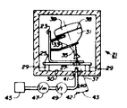
제 1 도는 본 발명의 제 1 실시예를 실행하기 위한 주기 오븐의 부분 절단정면도.1 is a partial cutaway front view of a cycle oven for implementing a first embodiment of the present invention.
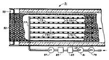
제 2 도는 본 발명의 제 2 실시예를 실행하기 위한 연속 벨트 오븐의 부분 절단정면도.2 is a partial cutaway front view of a continuous belt oven for implementing a second embodiment of the present invention.
제 3 도는 제 2 도의 절단선 3-3선을 따라 절취한 확대 단면도.3 is an enlarged cross-sectional view taken along the line 3-3 of FIG. 2;
제 4 도는 제 2 도의 절단선 4-4선을 따라 절취한 확대 단면도.4 is an enlarged cross-sectional view taken along the line 4-4 of FIG. 2;
제 5 도는 제 2 도에 도시된 오븐에 통과하는 튜브의 상승구간에서 수행된 온도 분포를 나타내는 그래프.5 is a graph showing the temperature distribution carried out in the rising section of the tube passing through the oven shown in FIG.
* 도면의 주요부분에 대한 부호의 설명* Explanation of symbols for main parts of the drawings
21, 51 : 오븐 23 : 봉인 고정구21, 51: oven 23: sealing fixture
25 : 세라믹 배트 29 : 세라믹 블록25: ceramic bat 29: ceramic block
31 : 유리 펀넬 35, 67 : 넥31: glass funnel 35, 67: neck
38 : 프리트 밀봉층 39 : 유리 면판 패널38: frit sealing layer 39: glass face plate panel
47 : 수동 밸브 49 : 시간 제어 밸브47: manual valve 49: time control valve
55 : 아이들러 풀리 57 : 드라이브 풀리55: idler pulley 57: drive pulley
75 : 노즐 87 : 제어밸브75: nozzle 87: control valve
본 발명은 CRT(음극선관)제조 방법에 관한 것으로, 구체적으로는 부분적으로 완성된 면판-패널 조립체가 구워지고 동시에 그 패널이 펀넬(funnel)조립체에 가열-밀봉되는 방법에 관한 것이다.The present invention relates to a cathode ray tube (CRT) manufacturing method, and more particularly to a method in which a partially completed faceplate-panel assembly is baked and the panel is heat-sealed in a funnel assembly.
CRT의 한 형태인 컬러 텔레비전 수상관은, (가) 면판 패널의 내벽에 형광 뷰잉 스크린 구조물을 형성하는 단계와, (나) 상기 스크린 구조물로부터 습기와 실질상 모든 유기 물질을 제거하기 위하여 높은 온도에서 상기 패널 조립체를 구워내는 단계와, (다) 높은 온도에서 패널-펀넬 조립체를 구워냄으로써 펀넬의 큰 개구에 패널을 가열-밀봉하는 단계와, (라) 상기 펀넬에 부착된 넥(neck)으로 전자총 장착 조립체를 밀봉하는 단계와, (마) 상기 조립체를 진공으로 만들어 밀봉하는 단계를 포함하는 방법에 의해 제조된다.A color television receiver, which is a form of CRT, comprises (a) forming a fluorescent viewing screen structure on the inner wall of the faceplate panel, and (b) removing the moisture and substantially all organic material from the screen structure at high temperatures. Baking the panel assembly, (c) heat-sealing the panel in a large opening of the funnel by baking the panel-funnel assembly at a high temperature, and (d) an electron gun with a neck attached to the funnel; Sealing the mounting assembly, and (e) vacuuming the assembly to seal it.
CRT제조 비용을 경감하고 CRT제조에 필요한 연료량을 줄이기 위하여, 구워내는 단계(나)와 (다)를 결합하는 것이 바람직하다. 이러한 구워내는 단계를 결합하기 위한 종래의 제안은 하나 또는 그 이상의 다음 이유로 인해 부분적으로만 성공을 거두었다. 종래의 어떤 방법들은 정상적인 공자 조업에서 사용하기에는 너무 느리다는 것이다. 종래의 어떤 방법들은 스크린 구조물에 있는 모든 유기 물질을 실질상 완전하게 제거하지 못하거나 뷰잉 스크린의 성능을 저하시켰다. 종래의 어떤 방법들은 패널과 펀넬 사이에 변색된 밀봉을 형성하며, 이러한 밀봉은 CRT를 작동할때 보통 나타나는 전기장에서 전기적 고장을 일으키기 쉽다.In order to reduce the cost of CRT production and to reduce the amount of fuel required for the production of CRT, it is desirable to combine the baking step (b) with (b). Conventional proposals for combining these baking steps have been only partially successful for one or more of the following reasons. Some conventional methods are too slow for normal Confucius operations. Some conventional methods have substantially failed to completely remove all organic material in the screen structure or degrade the viewing screen. Some conventional methods form discolored seals between panels and funnels, which are susceptible to electrical failures in the electric field normally encountered when operating a CRT.
종래의 방법에서와 같이 본 발명의 방법은 개구, 즉 비교적 좁은 넥을 갖는 유리 펀넬에 유리 면판을 가열-밀봉하는 동시에 그 패널과 펀넬의 내측면에 코팅으로부터 유기 물질의 상당한 양을 구워내는 단계로 이루어진다. 가열-밀봉 및 구워내는 단계는 실질적으로 유동없는 대기내에서 높은 온도로 수행된다. 다른 종래 방법과는 달리 본 발명은 가열-밀봉 단계의 온도 상승 주기 동안 상기 펀넬의 넥으로 산소 함유 기체의 분사 또는 퍼프(puff)간혈적으로 지시하는 단계를 포함한다.As in the conventional method, the method of the present invention involves the step of heating-sealing a glass faceplate in a glass funnel having an opening, i. Is done. The heat-seal and bake steps are carried out at high temperatures in a substantially flow free atmosphere. Unlike other conventional methods, the present invention involves spraying or puffing the oxygen-containing gas into the neck of the funnel during the temperature rise cycle of the heat-sealing step.
본 발명의 방법은 양호하게는 150℃ 내지 450℃범위의 온도에서 건조한 공기로 수행된다. "간헐적으로"라는 것은 기체의 분사가 다수의 연속시간 간격의 부분에 대하여 분사되는 것이 아니라 한 부분에 대하여 분사되는 것을 의미한다. 분사는 어떤 방향으로도 분사 가능하지만, 양호하게는 CRT의 넥의 종축에 대한 비교적 작은 각도에서 분사된다.The process of the invention is preferably carried out with dry air at a temperature in the range from 150 ° C to 450 ° C. By "intermittently" it is meant that the injection of gas is not directed over a portion of a plurality of continuous time intervals but for one portion. The spraying is possible in any direction, but is preferably sprayed at a relatively small angle to the longitudinal axis of the neck of the CRT.
본 발명의 방법은, 단일의 구워내는 단계에서 스크린 구조물로부터 실질상 모든 유기 물질을 제거하고, 정상의 열 밀봉 사이클을 이용하여 만족스러운 패널-펀넬 밀봉을 수행하며, 뷰잉 스크린의 성능을 저하시키지 않고, CRT를 제조하기 위한 다른 단계와 양립된다.The method of the present invention removes substantially all organic material from the screen structure in a single baking step, performs satisfactory panel-funnel sealing using normal heat sealing cycles, and does not degrade the viewing screen performance. Is compatible with other steps for producing CRTs.
본 발명의 방법의 단계는 일반적으로 새도우 마스크 CRT를 제조하는데 사용되는 단계와 동일하다. 일반적으로 새도우 마스크 CRT의 제조에 있어서, 유리 면판 패널은 전술한 방법에 의해, 예컨대 S.A.Claypoole가 1965년 6월 8일자로 출원한 U.S. 특허 제Re 25,791호에 기재된 방법에 의해 제거 가능한 유리 프리트(frit)로 유리 펀넬에 가열 밀봉된다. 패널을 펀넬에 가열-밀봉하기 전에, 마스크 조립체가 면판 패널에 장착되고 뷰잉 스크린 구조물이 패널의 내면상에 제조된다. 또한 펀넬에는 흑연으로 이루어진 내부의 전도 코팅부와 결합제가 제공된다. 펀넬은 보다 큰 단부에서 면판에 패널에 밀봉되기에 적합한 콘(cone)과, 보다 작은 단부에서 장착 조립체의 축을 수용하기에 적합한 완전 실린더형 넥으로 이루어진다.The steps of the method of the present invention are generally the same as those used to prepare the shadow mask CRT. In general, in the manufacture of shadow mask CRTs, the glass faceplate panel is prepared by the method described above, for example, in U.S. The glass funnel is heat-sealed with a glass frit removable by the method described in Patent Re 25,791. Prior to heat-sealing the panel to the funnel, the mask assembly is mounted to the faceplate panel and a viewing screen structure is fabricated on the inner surface of the panel. The funnel is also provided with an internal conductive coating and a binder made of graphite. The funnel consists of a cone suitable for sealing the panel to the faceplate at the larger end and a fully cylindrical neck adapted to receive the axis of the mounting assembly at the smaller end.
통상적으로, 뷰잉 스크린 구조물과 패널은 펀넬에 그 패널을 가열-밀봉하는 단계전에 별개의 단계로서 습기 및 유기 물질을 제거하기 위하여 높은 온도에서 구워진다. 본 발명의 방법은 상기 두 단계를 한번에 구워내는 것으로 수행함으로써 노동력, 설비, 연료 및 설치면적으로 절감하기 위하여 가열-밀봉의 나중 단계가 변경된다는 점에서 종래의 방법과는 상이하다.Typically, the viewing screen structure and the panel are baked at a high temperature to remove moisture and organic material as a separate step before the step of heat-sealing the panel to the funnel. The method of the present invention differs from the conventional method in that the later steps of heat-sealing are changed in order to save labor, equipment, fuel and installation area by performing the two steps at once.
본 방법은 제 1 도에 도시된 오븐(21)과 같은 주기 오븐내에서 수행되며, 밀봉될 부분들은 열처리를 통해서 고정되어 있는 봉인 고정구(23)내에 지지되어 있다. 봉인 고정구(23)는 배트 호울(27)을 갖는 내화성 세라믹 배트(25)상에 지지되어 있는 관형 프레임을 구비한다. 배트(25)는 복수의 내화성 세라믹 블록(29)에 지지되어 있으며, 이는 오븐의 바닥(30)에 놓여져 있다.The method is carried out in a periodic oven, such as the oven 21 shown in FIG. 1, wherein the parts to be sealed are supported in a sealing fixture 23 which is fixed through heat treatment. The sealing fixture 23 has a tubular frame that is supported on a refractory ceramic bat 25 having a bat hole 27. The batt 25 is supported on a plurality of refractory
유리 펀넬(31)은 하부에 있는 넥(35)과 상부에 있는 개방된 단부와 함께 고정구(23)의 지지 아암(23)내에 놓여진다. 넥(35)은 수직 방향에서 예각으로 놓인 종방향의 넥축(37)을 갖는다. 넥(35)의 개방 단부는 상부에 있으며 배트(25)내의 배트 호울(27)로부터 이격져 있다. 펀넬(31)의 상부 모서리는 유리 프리트 밀봉 물질층(38)을 갖는 밀봉영역을 구비한다. 유리 면판 패널(39)은 밀봉 물질층(38)상에 놓여 있는 대칭 밀봉 영역을 갖는다.The glass funnel 31 is placed in the support arm 23 of the fixture 23 with the neck 35 at the bottom and the open end at the top. The neck 35 has a
튜브(40)는 반대면 오븐 바닥(30)내의 작은 바닥 구멍(41)을 통과하며 배트(25)내의 배트 호울(27)로부터 일정한 간격을 유지하고 있다. 튜브(40)는 배트 호울(27)을 통과하고 넥(35)의 개방 단부에 대해 예각(43)으로 넥축(37)과 교차하는 튜브축(42)을 갖는다. 튜브(40)는 시간 제어밸브(49)와 수동밸브(47)을 통해 소스(45)로 부터 공기와 함께 간헐적으로 공급된다. 오븐(21)은 전기 저항가열 소자(도시않음)로써 제어방식을 가열된다.Tube 40 passes through a small bottom hole 41 in opposing
본 방법을 실행하기 위하여 갖가지 부품의 열려진 수동 밸브(47)와 함께 제 1 도에서와 같이 조립된다. 오븐(21)내의 대기는 유동이 없는 공기이다. 오븐(21)은 약 85분내에 약 440℃까지 가열되는데 이 온도는 약 55분 동안 유지되고, 그후 오븐(21)은 약 150분 내로 실온으로 냉각된다. 가열 주기의 초기 25분 동안, 튜브(40)를 통해서는 공기의 흐름이 없다. 다음에, 가열 주기의 나머지 60분 동안은 오븐 온도가 150℃ 내지 450℃의 범위내에 있을때, 시간 제어 밸브(49)가 교대로 약 20초 동안 개방되고 약 40초 동안 닫혀서, 넥(35)의 개방 단부를 향하여 튜브(40)로부터 간헐적으로 공기를 분출한다. 가열 주기의 끝부분에서 시간 제어밸브(49)가 폐쇄되어 가열 사이클의 나머지 시간 동안 폐쇄된 채로 남는다.It is assembled as in FIG. 1 with an open manual valve 47 of various parts for carrying out the method. The atmosphere in the oven 21 is air without flow. The oven 21 is heated to about 440 ° C. in about 85 minutes and this temperature is maintained for about 55 minutes, after which the oven 21 is cooled to room temperature in about 150 minutes. During the first 25 minutes of the heating cycle, there is no air flow through the tube 40. Next, when the oven temperature is in the range of 150 ° C to 450 ° C for the remaining 60 minutes of the heating cycle, the time control valve 49 alternately opens for about 20 seconds and closes for about 40 seconds, Air is blown out intermittently from the tube 40 toward the open end. At the end of the heating cycle the time control valve 49 closes and remains closed for the remainder of the heating cycle.
가열 주기 동안 유동이 없는 대기내에서 공기의 간헐적인 분사의 효과는 펀넬(31)내측에 있는 기체를 끌어내어 공기와 대체시키는 것이다. 다른 기술이 시도되었으나 덜 효과적이라는 것이 판명되었다. 예를들면, 공기의 간헐적인 분사 대신에 연속 분사는 연속 분사기류가 기체를 끌어내는 대신 펀넬내에 고이게 하는 것으로 판명되었기 때문에 효과적이지 못하다. 또한 분사가 없는 오븐내의 유동 대기는 넥을 통한 펀넬 내측과 오븐 대기사이의 아주 빈약한 기체 교환때문에 효과적이지 못하다. 넥축(37)은 튜브축(47)에 대해 소정 각도(43)로 놓여진다. 각도 0℃에서 즉 두측이 평행일때 넥(35)을 통한 기체의 교환이 적당하지만 각도가 약 15℃로 증가함으로써 더욱 향상된다. 소정의 산소 함유 기체가 사용될 수 있는데, 특히 -40℃이하의 이슬점을 갖는 건조 공기가 바람직하다.The effect of intermittent injection of air in the flow-free atmosphere during the heating cycle is to draw the gas inside the funnel 31 and replace it with air. Other techniques have been tried but turned out to be less effective. For example, instead of intermittent injection of air, continuous injection is not effective because it has been found that the continuous jet flows into the funnel instead of drawing gas. Also, the flow atmosphere in the oven without injection is not effective due to the very poor gas exchange between the funnel inside the neck and the oven atmosphere. The
본 방법은 제 2 도, 제 3 도 및 제 4 도에 도시된 오븐(51)과 같은 연속 터널 오븐내에서 실시되는데, 이는 본 방법의 새로운 특징에 관해 아래에 기술된 바를 제외하고는 비교적 유동이 없는 대기를 갖는 세 영역의 가열된 챔버를 구비한다. 철그물 벨트(53)는 입력 단부에 있는 아이들러 풀리(55)와 출력 단부에 있는 드라이브 풀리(57)상에 지지되는데, 이들 풀리는 챔버의 외부에 위치한다. 밸트(53)는 입력 단부의 아이들러 풀리(55)를 경유하여 각 단부에 있는 개구를 통해 챔버를 통과하여 그 챔버내의 중간 아이들러 풀리(56)를 거쳐서 드라이브 풀리(57)를 경유한다. 벨트(53)는 압력 단부의 아이들러 풀리(55)에 챔버를 하부와 외부로 되돌린다.The method is carried out in a continuous tunnel oven, such as the
벨트(53)는 그 벨트상의 각 점이 약 300분(5시간)동안 챔버내에 있고, 가열 영역에서는 약 90분, 중앙 소오킹 영역에서는 약 60분, 그리고 냉각 영역에서는 약 150분 동안 있는 비율로 터널 오븐(51)을 통해 이동한다. 벨트의 이동율 및 챔버내에의 시간 소비율은 본 실시예에서 주어진 것과는 상당한 차이가 있을 수 있으며 이는 본 기술 분야의 기술자에게 잘 알려져 있는 사실이다.The
벨트(53)가 이동함에 따라, 제 1 도에서의 고정구(23)와 유사한 고정구(59)가 벨트(53)위로 배치되고, 다섯개의 고정구(59)가 벨트(53)를 가로질러 일렬로 배열된다. 각 고정구(53)는 넓은 단부에서 밀봉 영역상에 프리트 밀봉 물질층(63)을 갖는 각 펀넬(61)과 함께 넥 하부에 놓인다. 그리고 나서, 내면상에 구워지지 않은 스크린 구조물을 갖는 면판 패널(65)이 밀봉 물질층(63)상의 매칭 밀봉 영역과 함께 펀넬(61)상에 장착된다. 가동 벨트를 교차하는 연속선은 오븐(51)의 챔버를 거쳐 이동하는 고정구(59)의 다섯 컬럼을 제공한다.As the
각 고정구(59)에서, 펀넬(61)은 넥(67)의 개방 단부가 드라이브 풀리(57)를 향하여 약 15°의 예각(69)으로 기울어지고 또한 벨트(53)의 중심을 향하여 약 10°의 예각(71)으로 기울어지도록 경사져 있다. 고정구 각 컬럼의 넥(67) 아래와 또한 벨트(53) 아래에 그 벨트(53)를 통해 수직 상방으로 향한 복수의 이격진 노즐(75)과 함께 매니 포울드(73)가 수직으로 놓여져 있다. 각 매니포울드(73)는 해더(77)에 접속되며, 이 헤드는 수동 밸브(79), 정압 출구 밸브(81), 건조기(83), 유량계(85) 및 제어밸브(87)를 통해 압축 공기의 소스(도시않음)에 접속되어 있다. 노즐(75)의 배열은 오븐의 가열 영역 부분만을 거쳐 연장한다.In each
본 실시예에 있어서, 고정구(59)와 함께 벨트(53)는 드라이브 풀리(57)의 방향으로 실질상 일정한 비율로 이동한다. 이와 동시에, 헤더를 통과하는 건조 공기는 다섯개의 매니포울드(73)로 확산되어 밸트(53)를 통해 수직 상방으로 향한 노즐(75)로 부터 일정 유량으로 분출된다. 고정구(59)가 이동함에 따라, 펀넬의 넥(67)의 개방 단부는 하부 노즐 컬럼으로부터 분출하는 연속 분사 기류를 통과한다. 넥(67)의 개방 단부는 연속 노즐로부터 분출하는 분사기류의 내부 및 외부에서 교대적이며, 이들 노즐은 충분히 이격져 있다. 각 펀넬(61)의 효과는 그 넥으로 간헐적으로 향하는 산소 함유 기체의 분사를 수행하는데 있다.In the present embodiment, the
제 5 도는 오븐(51)내에서의 경과 시간(분)대 오븐(51)을 통과하는 통상의 25V 100°의 밀봉 영역 상승 구간의 온도(℃)를 도시한 그래프이다. 제 5 도에서 빗금친 부분은 공기가 분사되는 동안의 가열 사이클부분을 나타낸다. 이 사이클의 다른곳에서는 분사가 되지 않는다. 일반적으로 상당히 약한 대류를 제외하고는 오븐 내의 대기는 본질적으로 유동이 없다.5 is a graph showing the elapsed time (minutes) in the
Claims (9)
Applications Claiming Priority (2)
| Application Number | Priority Date | Filing Date | Title |
|---|---|---|---|
| US458653 | 1983-01-17 | ||
| US06/458,653 US4493668A (en) | 1983-01-17 | 1983-01-17 | Method for combined baking-out and panel-sealing of a partially-assembled CRT |
Publications (2)
| Publication Number | Publication Date |
|---|---|
| KR840007298A KR840007298A (en) | 1984-12-06 |
| KR920004638B1 true KR920004638B1 (en) | 1992-06-12 |
Family
ID=23821590
Family Applications (1)
| Application Number | Title | Priority Date | Filing Date |
|---|---|---|---|
| KR1019840000189A KR920004638B1 (en) | 1983-01-17 | 1984-01-17 | Method for combined baking-out and panel-sealing of a partilly-assembled crt |
Country Status (8)
| Country | Link |
|---|---|
| US (1) | US4493668A (en) |
| JP (1) | JPS59138035A (en) |
| KR (1) | KR920004638B1 (en) |
| CA (1) | CA1229131A (en) |
| FR (1) | FR2539553B1 (en) |
| GB (1) | GB2135504B (en) |
| HK (1) | HK41391A (en) |
| IT (1) | IT1174467B (en) |
Families Citing this family (6)
| Publication number | Priority date | Publication date | Assignee | Title |
|---|---|---|---|---|
| DE3439198C2 (en) * | 1984-10-26 | 1993-10-14 | Nokia Deutschland Gmbh | Rack for a cathode ray tube |
| US4923423A (en) * | 1989-06-30 | 1990-05-08 | Rca Licensing Corporation | Integrated thermal processing for kinescopes |
| JP3089480B2 (en) * | 1990-09-20 | 2000-09-18 | ソニー株式会社 | Frit sealing device |
| US5145511A (en) * | 1991-11-08 | 1992-09-08 | Videocolor Spa | Method for manufacturing a metallized luminescent screen for a cathode-ray tube |
| US5405722A (en) * | 1993-12-22 | 1995-04-11 | Rca Thomson Licensing Corp. | Method for combined baking-out and sealing of an electrophotographically processed screen assembly for a cathode-ray tube |
| DE10003664B4 (en) * | 2000-01-28 | 2007-03-22 | Elino Industrie-Ofenbau Carl Hanf Gmbh & Co. Kg | Method and apparatus for heat treatment of picture tubes |
Family Cites Families (13)
| Publication number | Priority date | Publication date | Assignee | Title |
|---|---|---|---|---|
| US3041127A (en) * | 1959-12-22 | 1962-06-26 | Rca Corp | Method of fabricating a cathode ray tube |
| US3658401A (en) * | 1970-01-06 | 1972-04-25 | Rca Corp | Method of manufacture of cathode ray tubes having frit-sealed envelope assemblies |
| US3932011A (en) * | 1974-06-05 | 1976-01-13 | Rca Corporation | Conditioning partially-completed CRT bulb assembly for storage and/or transit |
| US4058387A (en) * | 1975-07-03 | 1977-11-15 | Owens-Illinois, Inc. | Simultaneously baking and sealing a faceplate assembly |
| JPS5396663A (en) * | 1977-02-04 | 1978-08-24 | Hitachi Ltd | Manufacture of cathode-ray tube |
| JPS53123654A (en) * | 1977-04-04 | 1978-10-28 | Hitachi Ltd | Production of color picture tube |
| US4154494A (en) * | 1977-05-23 | 1979-05-15 | Corning Glass Works | Process for manufacturing cathode ray tube bulbs |
| JPS5480669A (en) * | 1977-12-09 | 1979-06-27 | Sony Corp | Manufacture for cathode ray tube and ventilation unit used for its sintering process |
| US4213663A (en) * | 1978-12-26 | 1980-07-22 | Rca Corporation | Wet carbon-dioxide treatment of partially-completed CRT |
| JPS56134446A (en) * | 1980-03-26 | 1981-10-21 | Hitachi Ltd | Manufacturing device and method of color picture tube |
| JPS56149745A (en) * | 1980-04-22 | 1981-11-19 | Toshiba Corp | Manufacturing method for cathode-ray tube |
| JPS56162451A (en) * | 1980-05-19 | 1981-12-14 | Hitachi Ltd | Manufacture of color-picture tube and its device |
| JPS6113343A (en) * | 1984-06-28 | 1986-01-21 | Fujitsu Ltd | Console device |
-
1983
- 1983-01-17 US US06/458,653 patent/US4493668A/en not_active Expired - Lifetime
- 1983-12-28 CA CA000444350A patent/CA1229131A/en not_active Expired
-
1984
- 1984-01-12 JP JP59004232A patent/JPS59138035A/en active Granted
- 1984-01-13 IT IT19160/84A patent/IT1174467B/en active
- 1984-01-13 FR FR8400493A patent/FR2539553B1/en not_active Expired
- 1984-01-13 GB GB08400910A patent/GB2135504B/en not_active Expired
- 1984-01-17 KR KR1019840000189A patent/KR920004638B1/en not_active IP Right Cessation
-
1991
- 1991-05-30 HK HK413/91A patent/HK41391A/en not_active IP Right Cessation
Also Published As
| Publication number | Publication date |
|---|---|
| US4493668A (en) | 1985-01-15 |
| JPH047529B2 (en) | 1992-02-12 |
| HK41391A (en) | 1991-06-07 |
| JPS59138035A (en) | 1984-08-08 |
| IT8419160A0 (en) | 1984-01-13 |
| GB8400910D0 (en) | 1984-02-15 |
| FR2539553A1 (en) | 1984-07-20 |
| GB2135504A (en) | 1984-08-30 |
| IT1174467B (en) | 1987-07-01 |
| GB2135504B (en) | 1986-05-14 |
| KR840007298A (en) | 1984-12-06 |
| CA1229131A (en) | 1987-11-10 |
| FR2539553B1 (en) | 1988-05-13 |
Similar Documents
| Publication | Publication Date | Title |
|---|---|---|
| KR920004638B1 (en) | Method for combined baking-out and panel-sealing of a partilly-assembled crt | |
| EP1216971A1 (en) | The method for manufacturing vacuum glazing and its application mechanical system | |
| US2824364A (en) | Method of assembling and evacuating an insulated vacuum panel | |
| US4923423A (en) | Integrated thermal processing for kinescopes | |
| US4350514A (en) | Method for manufacturing cathode ray tubes | |
| JPS57188434A (en) | Manufacture apparatus for heat ray reflecting glass | |
| JPH11329246A (en) | Plasma display panel and its manufacture | |
| US6527547B2 (en) | Oven and process for manufacturing an envelope for use in a display tube | |
| US4000997A (en) | Method for reducing thermally induced fracture in cathode ray tube bulbs | |
| US3988136A (en) | Method for reducing thermally induced fracture of cathode ray tube bulbs during salvage | |
| CN201229911Y (en) | Vacuum sealing exhausting apparatus for plasma display screen | |
| KR100575131B1 (en) | Method for manufacturing plasma display panel | |
| US5160287A (en) | Color picture tube manufacturing method | |
| US4979919A (en) | Method and apparatus for manufacturing cathode-ray tubes | |
| KR100329775B1 (en) | Exhaustion/seal apparatus and method for manufacturing of plasima display panel | |
| KR100275263B1 (en) | Sealing method of field emission display in vacuum chamber | |
| KR20230073773A (en) | Substrate processing apparatus | |
| JPS6043619B2 (en) | Cathode ray tube manufacturing method | |
| JPH11162352A (en) | Evacuation equipment for glass board assembly with chip tube | |
| JPS6057176B2 (en) | Cathode ray tube manufacturing method | |
| SU948988A1 (en) | Apparatus for making heat insulating panels | |
| US2956374A (en) | Glass bulb fabrication | |
| SU1050823A1 (en) | Method of producing hermetically sealed relay | |
| DE10003664B4 (en) | Method and apparatus for heat treatment of picture tubes | |
| JPS61269834A (en) | Manufacture of color picture tube |
Legal Events
| Date | Code | Title | Description |
|---|---|---|---|
| A201 | Request for examination | ||
| E902 | Notification of reason for refusal | ||
| G160 | Decision to publish patent application | ||
| E701 | Decision to grant or registration of patent right | ||
| GRNT | Written decision to grant | ||
| FPAY | Annual fee payment |
Payment date: 20030520 Year of fee payment: 12 |
|
| EXPY | Expiration of term |