KR920004204B1 - Vacuum filter - Google Patents
Vacuum filter Download PDFInfo
- Publication number
- KR920004204B1 KR920004204B1 KR1019850000609A KR850000609A KR920004204B1 KR 920004204 B1 KR920004204 B1 KR 920004204B1 KR 1019850000609 A KR1019850000609 A KR 1019850000609A KR 850000609 A KR850000609 A KR 850000609A KR 920004204 B1 KR920004204 B1 KR 920004204B1
- Authority
- KR
- South Korea
- Prior art keywords
- filter
- tray
- trays
- endless
- vacuum
- Prior art date
Links
Images


Classifications
-
- B—PERFORMING OPERATIONS; TRANSPORTING
- B01—PHYSICAL OR CHEMICAL PROCESSES OR APPARATUS IN GENERAL
- B01D—SEPARATION
- B01D33/00—Filters with filtering elements which move during the filtering operation
- B01D33/29—Filters with filtering elements which move during the filtering operation the movement of the filter elements being a combination of movements
-
- B—PERFORMING OPERATIONS; TRANSPORTING
- B01—PHYSICAL OR CHEMICAL PROCESSES OR APPARATUS IN GENERAL
- B01D—SEPARATION
- B01D33/00—Filters with filtering elements which move during the filtering operation
- B01D33/04—Filters with filtering elements which move during the filtering operation with filtering bands or the like supported on cylinders which are impervious for filtering
-
- B—PERFORMING OPERATIONS; TRANSPORTING
- B01—PHYSICAL OR CHEMICAL PROCESSES OR APPARATUS IN GENERAL
- B01D—SEPARATION
- B01D33/00—Filters with filtering elements which move during the filtering operation
- B01D33/44—Regenerating the filter material in the filter
- B01D33/48—Regenerating the filter material in the filter by flushing, e.g. counter-current air-bumps
- B01D33/50—Regenerating the filter material in the filter by flushing, e.g. counter-current air-bumps with backwash arms, shoes or nozzles
- B01D33/503—Regenerating the filter material in the filter by flushing, e.g. counter-current air-bumps with backwash arms, shoes or nozzles the backwash arms, shoes acting on the cake side
Abstract
Description
제 1 도는 번갈아 배열된 트레이(tray) 열에 의해 형성된 수평필터영역을 도시한 본 발명의 진공필터의 개략적인 측면도.1 is a schematic side view of a vacuum filter of the present invention showing a horizontal filter area formed by alternating rows of trays.
제 2 도는 제 1 도의 선(II-II)에 의한 단면도.2 is a cross-sectional view taken along the line II-II of FIG.
제 3 도는 도면의 지면방향으로 연장하는 장착지지부 및 배출부를 갖는 트레이의 중앙 및 우측부분을 도시한 동시에 여과물 배출부의 연결부를 갖는 트레이를 도시한 제 2 도의 부분확대 단면도.FIG. 3 is a partially enlarged cross-sectional view of FIG. 2 showing a tray having a connection portion of the filtrate discharge while showing a center and a right portion of the tray having a mounting support and an outlet extending in the direction of the drawing in the drawing;
제 4 도는 두개의 인접한 트레이의 밀봉맞물림 상태를 도시한 트레이의 회전방향으로의 종단면도.4 is a longitudinal sectional view in the direction of rotation of the tray showing the sealing engagement of two adjacent trays.
제 5 도는 제 4 도의 선(V-V)에 의한 단면도.5 is a cross-sectional view taken along the line V-V of FIG.
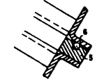
제 6 도는 트레이 가장자리의 확대도.6 is an enlarged view of the tray edge.
제 7 도는 제 6 도의 선(VII-VII)에 의한 단면도.FIG. 7 is a cross-sectional view taken along the line VII-VII of FIG. 6.
* 도면의 주요부분에 대한 부호의 설명* Explanation of symbols for main parts of the drawings
1 : 트레이 2 : 그리드1: tray 2: grid
3 : 둑 4 : 풀리3: dam 4: pulley
7 : 필터영역 8 : 클램프7: Filter area 8: Clamp
9 : 벨트 10 : 캠9: belt 10: cam
11 : 안내풀리 12 : 체인11: guide pulley 12: chain
13 : 안내레일 14 : 치형풀리13: guide rail 14: toothed pulley
15 : 모터 16 : 진공채널15: motor 16: vacuum channel
18 : 내구성벨트 19 : 필터직물18: durable belt 19: filter fabric
20 : 케익배출롤러 21, 34 : 롤러20:
22 : 안내롤러 23 : 인장시스템22: guide roller 23: tensioning system
33 : 필터출구 35 : 세척장치33: filter outlet 35: washing device
37 : 캡스트립 41 : 필터 프레임37: cap strip 41: filter frame
42 : 선회장치42: turning device
본 발명은 액체로부터 고체를 분리시키기 위한 진공필터에 관한 것으로, 특히, 이격된 바퀴부재의 둘레로 종방향으로 회전하는 탄성벨트를 마련한 수평 트레이 필터에 관한 것이다. 벨트는 거기에 고정된 무단부종렬의 트레이를 마련하고 있으며 트레이는 수평필터영역안에 형성된 고정진공채널상에 미끄러진다.The present invention relates to a vacuum filter for separating solids from a liquid, and more particularly, to a horizontal tray filter provided with an elastic belt rotating longitudinally around a spaced wheel member. The belt is provided with an endless tray fixed therein which slides on a fixed vacuum channel formed in the horizontal filter area.
수평 트레이 진공필터는 공지된 것으로서 수평구조의 여과구역에 의해 다용도의 양호한 여과를 제공하고, 필터케익형성체가 중력에 의해 지지되는 동시에 케익세척이 가장 효과적으로 수행될 수 있는 것이다. 어떠한 수평필터는 케익방출을 위하여 기울어질 수 있는 독립적으로 분할된 팬으로서 필터영역의 둘레로 회전하는 디스크 또는 팬을 마련하고 있다. 기타의 그러한 기계로서는 왕복운동하는 팬필터나 단속벨트필터가 알려져 있지만, 이는 필터직물이 팬에 대하여 이동되거나 또는 그 역으로 되고 진공이 중단될때 연속적인 여과작업을 수행할 수 없는 단점을 갖고 있다. 이러한 단속적인 여과작업은, 특히, 현탁액재료의 신속한 여과가 필요한 경우에 이러한 필터의 사용분야를 제한한다. 또한, 이러한 공지의 기계의 필터케익의 세척은 비효율적이고 복잡하며, 필터의 작동을 위해 난해한 제어시스템이 필요하다.Horizontal tray vacuum filters are known and provide a good versatility of filtration by a horizontal filtration zone, and the cake cleaning can be most effectively carried out while the filter cake forming body is supported by gravity. Any horizontal filter is an independent split fan that can be tilted for cake release, with a disk or fan rotating around the filter area. Other such machines are known as reciprocating fan filters or intermittent belt filters, but this has the disadvantage of not being able to carry out continuous filtration when the filter fabric is moved relative to the fan and vice versa and the vacuum is stopped. Such intermittent filtration limits the field of use of such filters, particularly where rapid filtration of the suspension material is required. In addition, the cleaning of filter cakes of such known machines is inefficient and complex, and difficult control systems are required for the operation of the filters.
도날드슨(Donaldson)의 미합중국특허 제 1,862,050호에 도시된 형태의 필터에 있어서는, 팬필터에 트레이를 마련한 진공필터가 도시되어 있으며, 트레이는 팬의 둘레로 폐쇄테를 갖는 각각의 단일팩속으로 틀어막힌 필터직물과 함께 콘베이어처럼 설비되며, 각 팬은 하부진공 여과채널에 독립적인 연결부를 가짐으로써 팬과 진공채널사이에 활주밀봉이 이루어진다. 이런 형태의 필터는, 복잡한 기계적인 설계가 필요한 단점이 있다. 또한, 케익이 불완전하게 방출되거나 필터직물의 세척이 비효율적이다.In the filter of the type shown in US Patent No. 1,862,050 to Donaldson, there is shown a vacuum filter having a tray in a fan filter, the tray being plugged into each single pack having a closed frame around the fan. It is installed like a conveyor with the fabric, and each fan has a sliding connection between the fan and the vacuum channel by having independent connections to the lower vacuum filtration channel. This type of filter has the disadvantage of requiring complex mechanical design. In addition, the cake is incompletely released or the cleaning of the filter fabric is inefficient.
또한, 수평진공필터에 있어서 콘베이어벨트의 원리에 따라 여과구역위에 무단부 필터직물을 제공하는것은 잘 알려져 있다. 일반적으로 이러한 필터는 무단부 필터직물을 지지하기 위하여 예를들어 1m 내지 6m의 폭을 갖는 무거운 무단부 고무벨트를 마련한다. 이 고무벨트는 여과구역에서 진공여과채널과 활주밀봉이 이루어지도록 설계된다. 이러한 공지의 고무벨트필터는 무겁고 취급 및 조립이 힘들며 가격이 비싼 단점이 있다. 사용후에 마모에 의해 고무벨트를 교환하여야 할때 이 기계는 완전히 분해되어야만 한다. 또한, 고무벨트와 접촉이 이루어지지 않는 현탁액의 특정액체에 있어서는 이러한 종류의 필터의 사용이 제한된다. 그러나, 이러한 공지의 고무벨트필터로써 기계에 대한 입구 및 출구에서 필터영역상에 벨트에 의하여 필터직물을 안내함으로써 여과구역의 외측에서 세척장치를 필터직물의 일반적인 청소를 위해 사용할 수 있다. 이러한 공지의 고무벨트필터의 단점은 부피가 큰 고무벨트의 무거운 무게와 조립공정의 어려움, 그리고 그 투자 경비가 큰 것이다.It is also well known to provide endless filter fabrics over filtration zones in accordance with the principle of conveyor belts in horizontal vacuum filters. Generally, such filters provide heavy endless rubber belts having a width of, for example, 1 m to 6 m to support endless filter fabrics. This rubber belt is designed to be vacuum filtration channel and slide seal in filtration area. Such known rubber belt filters are heavy, difficult to handle and assemble, and expensive. When the rubber belt needs to be replaced by wear after use, the machine must be completely disassembled. In addition, the use of this kind of filter is limited for certain liquids in suspension which are not in contact with the rubber belt. However, with this known rubber belt filter, a cleaning device outside the filtration zone can be used for general cleaning of the filter fabric by guiding the filter fabric by means of a belt on the filter area at the inlet and outlet of the machine. The disadvantages of such known rubber belt filters are the heavy weight of the bulky rubber belt, the difficulty of the assembly process, and the high investment costs.
본 발명의 목적은 필터직물을 세척할 수 있는 동시에 필터작동의 어려움을 최소로 할 수 있는 신규의 수평팬 또는 트레이식 진공벨트를 제공하는 것이다. 이러한 목적을 달성하기 위하여, 무단부 필터직물을 여과 구역위의 트레이의 둘레로 마련하고 세척장치를 여과구역의 외측에 위치시킴으로써 트레이의 각각이 인접한 트레이와 전방 및 후방에서 밀봉맞물림이 이루어지고 각 트레이는 테가 없이 형성되어 트레이를 연결한 종렬이 하나의 필터영역을 형성하도록 구성되어 있다. 또한, 모든 트레이는 탄성 무단부벨트에 고리 연결되고 무단부벨트가 여과액의 배출을 위한 개구부위로 진공채널과 연결되어 무단부벨트에 고리 연결되고 무단부벨트가 여과액의 배출을 위한 개구부위로 진공채널과 연결되어 무단부벨트가 진공채널상에서 활주하는 방법으로 안내되도록 구성된다. 무단부 필터벨트를 지지하는 트레이는 양측면상에서 개구되어 있고 가장자리가 없어서 수평위치에 조립된 트레이는 단일의 큰 여과구역을 형성한다. 각 트레이는 하부에서 진공채널과 고유한 연결부를 가지며, 트레이와 진공채널이 서로 활주밀봉부를 형성하도록 조립된다.It is an object of the present invention to provide a novel horizontal fan or tray type vacuum belt which can clean the filter fabric and at the same time minimize the difficulty of filter operation. To achieve this purpose, endless filter fabrics are provided around the tray over the filtration zone and the washing apparatus is positioned outside the filtration zone so that each of the trays is sealingly engaged in front and rear with adjacent trays and each tray Is formed without a frame so that the column connecting the trays forms one filter area. In addition, all the trays are looped to the elastic endless belt, the endless belt is connected to the vacuum channel over the opening for the discharge of the filtrate, and the endless belt is looped to the endless belt, and the endless belt is vacuumed over the opening for the discharge of the filtrate. It is configured to be connected to the channel so that the endless belt is guided by sliding on the vacuum channel. The trays supporting the endless filter belts are open on both sides and have no edges so that the trays assembled in the horizontal position form a single large filtration zone. Each tray has a unique connection with the vacuum channel at the bottom and is assembled such that the tray and the vacuum channel form a sliding seal with each other.
본 발명의 상기 및 기타의 목적과 장점은 본 발명의 한 실시예로써 도시한 첨부된 도면과 함께 아래에서 보다 상세히 설명함으로써 이해될 수 있을 것이다.The above and other objects and advantages of the present invention will be understood from the following more detailed description taken in conjunction with the accompanying drawings showing as an embodiment of the present invention.
제 1 도 및 제 2 도에 의하면, 진공필터는 종방향으로 이격된 위치에 설치된 풀리(4)와 치형풀리(14)를 구비함으로써 치형풀리(14)는 구동용이고 풀리(4)는 피동된다. 제 1 도와 제 2 도를 비교하면, 다수의 U형 트레이(1)의 이동방향으로 두개의 치형풀리(14)가 서로 측면으로 이격된 거리를 갖고 설치됐음을 알 수 있다. 치형풀리(14)는 모터(15)의 구동축(24)상에 고정되고, 모터(15)는 적절한 워엄기어를 구비한 다이리스터 모터(15 ; Thyristor motor)이다.According to FIGS. 1 and 2, the vacuum filter has a pulley 4 and a toothed pulley 14 installed in the longitudinally spaced position so that the toothed pulley 14 is driven and the pulley 4 is driven. . Comparing FIG. 1 with FIG. 2, it can be seen that two toothed pulleys 14 are installed at a distance from the side in the moving direction of the plurality of U-shaped trays 1. The toothed pulley 14 is fixed on the
(제 3 도에서 단면도로 도시된) 치형풀리(14)는 치부를 통해 고무콘베이어체인(12)의 대응치부(25)와 맞물리고, 체인은 외이어(26)와 볼트(27)로 보강되는 동시에 너트(28)에 의해 체결된다. 체인(12)은 각 트레이(1)의 하부면에 고정된 캠(10)상에 고정된다. 이러한 연결부는 제 3 도와 우측에 도시되어 있으나, 제 2 도에서는 트레이(1)와의 이중연결부를 갖는 것이 도시되어 있다. 트레이(1)를 이동시키기 위해 캠(10)의 중앙에는 구멍(29)이 구비되어 체인(12)의 볼트를 수용한다.The toothed pulley 14 (shown in cross section in FIG. 3) engages with the
안내풀리(11)의 축(31)을 위하여 캠(10)의 이동방향으로 구멍(30)이 구비된다. 안내풀리(11, 제 5 도)는 안내릴(13)의 이동된 위치에 도시되어 있다. 간단히 도시하기 위하여, 안내릴(13)은 제 1 도 및 제 3 도에 도시되어 있지 않지만 안내릴(13)안에 안내풀리(11)를 지지함으로써 트레이(1)의 바닥부에 용접된 캠(10)위에서 종방향으로 양측부로 각각의 트레이가 안내되는 것을 알 수 있다. 체인(12)의 양측면은 두개의 안내풀리사이의 캠(10)에 고정된다.A
진공필터의 회전방향(32)은 반시계방향으로 구부러진 화살표로 제 1 도에 도시되어 있다. 회전시에, 고무 체인(12)은 무단부 종렬의 이동가능하게 고정된 트레이(1)와 함께 이동된다. 트레이는 연속필터영역 또는 데크(7)를 형성한다. 공지의 필터에서와 같이, 고정진공채널(16)은 제 3 도에 도시된 바와같이 적절한 필터출구(33)를 구비하여 각 트레이의 바닥측면과 활주접촉되도록 종렬의 트레이(1)의 근처에 종방향으로 연장된 방향으로 배열되어 있다.The direction of rotation 32 of the vacuum filter is shown in FIG. 1 by an arrow bent counterclockwise. In rotation, the
밴드형 무단부 필터직물(19)은 추적롤러(21)와 안내롤러(22) 및 인장시스템(23)에 의해 필터직물(19)의 주름형성이 회피되면서 다양한 롤러(34)위로 공급된다. 필터케익용의 어떠한 양호한 형태의 배출시스템도 제공될 수 있지만, 케익배출롤로(20)가 구비된다. 무단부 필터벨트(19)는 트레이(1)에 구비되고 그것과 동시에 이동되는 그리드(2 : 제 4 도와 제 5 도)의 전표면에 안내된다.The band endless filter fabric 19 is fed onto a variety of
진공채널(16)위의 영역의 여과구역은 종렬의 트레이(1)의 측면으로 넓혀진다. 세척장치(35)는 제 1 도의 우측에 물분사노즐로서 도시되어 있고 여과구역외측에 배치된다.The filtration zone in the area above the vacuum channel 16 widens to the side of the tray 1 in the row. The
앞에서 언급한 바와같이 본 발명의 목적은 트레이(1)의 신규한 구조를 마련하는 것이다. 이를 위하여, 각트레이(1)는 각 트레이(1)의 이동방향으로 테가 없이 구비되어 있다. 제 4 도에 명백히 도시된 바와같이, 연결식 트레이의 양단부 모서리는 보강와이어(6)가 구비된 탄성밀봉체 스트립에 의해 밀봉설비된 채로 유지된다.As mentioned above, an object of the present invention is to provide a novel structure of the tray 1. To this end, each tray 1 is provided without a frame in the moving direction of each tray (1). As clearly shown in FIG. 4, the edges of both ends of the linked tray are kept sealed by an elastic seal strip provided with a reinforcing wire 6.
제 2 도, 제 3 도, 제 5 도 및 제 6 도에서, 이동방향에의 트레이(1)의 인접한 측벽의 맞물림은 둑(3)으로 기능하고 트레이(1)의 전방 및 후방단부는 단일의 균일하고 연속한 필터영역(7)으로부터 서로 맞닿아 있다. 또한 그리드(2)은 필터직물(19)을 위한 지지영역을 형성하고 있다. 각 그리드(2)는 손쉽게 장착 및 해체될 수 있는 (제 4 도의) 캡스트립(37)의 스냅식 맞물림이 이루어지도록 하향 연장된 다리부를 구비하고 있다. 캡스트립(37)은 각 트레이(1)의 하부부분(38)의 전방 및 후방단부의 테(36)의 모두에 설치된다. 이러한 전방 또는 후방의 테(36)는 밀봉테라고 지칭되기도 한다.2, 3, 5 and 6, the engagement of adjacent sidewalls of the tray 1 in the direction of movement functions as a weir 3 and the front and rear ends of the tray 1 are single. They are in contact with each other from the uniform and continuous filter area 7. The
제 3 도에서, 각 트레이(1)는 트레이(1) 바닥부의 중심선(39) 근처의 클램프(8)에 의해 고무벨트(9)와 연결된 여과를 출구노즐을 갖는다. 벨트(9)는 일종의 회전콘베이어로서 안내되고, 진공채널(16)의 활주면(17)상에 서로 평행하게 배열된 두개의 무단부 내구성 벨트(18)위로 미끄러진다. 활주면은 양호하게는 부가적인 폴리테트라플루오르에틸렌 봉으로 설치된다. 하부부분에서 내구성 벨트(18)는 필터프레임(41)의 다른부분에 고정된 지지롤러(40)상에 안착된다. 폴리테트라플루오르에틸렌 봉으로 된 면(17)은 벨트(9)의 마모를 감소시키고 필요할때 손쉽게 값싸게 교체할 수 있다.In FIG. 3, each tray 1 has an outlet nozzle for filtration connected to the rubber belt 9 by a clamp 8 near the centerline 39 at the bottom of the tray 1. The belt 9 is guided as a kind of rotary conveyor and slides on two endless endless belts 18 arranged parallel to each other on the sliding
내구성 벨트나, 가능하다면, 회전고무벨트(9)가 진공채널(16)등을 청소하기 위해 분해되어야 할때 채널(16)과 내구성 벨트(18)의 완전한 유니트가 제 2 도에 도시된 선회장치(42)에 의해 고무벨트(9)에서의 노즐과 함께 클램프(8)를 이완시킨 후에 외측으로 선회될 수 있다. 선회장치(42)는 고정금속판(44)에 고정된 유압실린더(43)와 성회판(45)으로 구성된다. 선회판(45)에 닿음으로서 선회판은 회전지점(46)의 둘레로 진공 체널(16)과 함께 아래로 선회된다. 선회장치는 또한 수동으로 작동할 수 있는 평형추를 마련하고 있다.The complete unit of the channel 16 and the durable belt 18 is shown in FIG. 2 when the durable belt or, if possible, the rotary rubber belt 9 has to be disassembled to clean the vacuum channel 16 or the like. By means of 42 it can be pivoted outwards after the clamp 8 is relaxed with the nozzle in the rubber belt 9. The turning device 42 is composed of a hydraulic cylinder 43 and a swash plate 45 fixed to the fixed metal plate 44. By touching the pivot plate 45, the pivot plate is pivoted down with the vacuum channel 16 around the rotation point 46. The turning device also has counterweights that can be operated manually.
본 분야에 속한 사람에 의해 쉽게 이해되는 바와 같이, 본 발명은 많은 장점을 가지고 있다. 내구성 벨트는 탄성무단부벨트 하부근처 및 무단부벨트의 양측면상의 고정진공채널의 활주표면위의 여과구역에 이동가능하게 설치된다. 벨트는 청소를 위해 쉽게 교환, 수선 또는 제거할 수 있다. 내구성 벨트와 탄성무단부벨트는 매우작고, 필터영역을 형성하는 유사한 필터용의 공지된 고무벨트보다 무게가 가볍다. 본 발명의 유사한 필터용의 공지된 고무벨트보다 무게가 가볍다. 본 발명에 의한 탄성무단부벨트의 폭과 두께 및 조립체는 공지의 고무벨트의 크기 및 중량의 일부만으로 가능하다.As will be readily understood by one of ordinary skill in the art, the present invention has many advantages. The durable belt is movably installed in the filtration zone near the bottom of the elastic endless belt and on the sliding surface of the fixed vacuum channel on both sides of the endless belt. The belt can be easily replaced, repaired or removed for cleaning. Durable belts and elastic endless belts are very small and lighter than known rubber belts for similar filters forming the filter area. Lighter weight than known rubber belts for similar filters of the present invention. Width and thickness of the elastic endless belt and the assembly according to the present invention is possible only a part of the size and weight of the known rubber belt.
또다른 장점은 진공채널을 프레임에 선회가능하게 대우시켜 진공채널과 인접한 부재의 청소 또는 내구성 벨트의 교환이 가능한 것이다. 진공채널은 필터직물 또는 트레이를 해체하지 않고 작동위치로부터 끄집어내거나 그 위치에 바깥으로 선회시킬 수 있다. 따라서, 필요한 청소, 정비 및 수선을 손쉽게 수행할 수 있다.Another advantage is the rotatable treatment of the vacuum channel to the frame, which enables cleaning of the member adjacent to the vacuum channel or replacement of the durable belt. The vacuum channel can be pulled out of the operating position or pivoted out of the position without disassembling the filter fabric or tray. Therefore, necessary cleaning, maintenance and repair can be easily performed.
본 발명의 다른 장점은 그리드를 플라스틱으로 제조할 수도 있으며, 충분한 강성을 갖는 동시에 적절한 가요성을 갖는 다른 재료로도 가능한 것이다. 이는 그리드의 전방 및 후방단부를 트레이의 이동방향으로 캡스트립 하부근처에서 스냅식 결합할 수 있도록 한다. 캡스트립은 각 스트립의 하부부분에 고정되고 이에 따라 수선 및 유지를 진공필터의 정지의 우려가 없이 손쉽게 수행할 수 있다.Another advantage of the present invention is that the grid can be made of plastic and can be made of other materials having sufficient rigidity and at the same time adequate flexibility. This allows snapping of the front and rear ends of the grid near the capstrip in the direction of the tray's movement. The capstrip is fixed to the lower part of each strip, so that repair and maintenance can be easily performed without fear of stopping the vacuum filter.
본 발명의 실시예가 도시되고 상세히 설명되었지만, 본 발명은 이에 제한되지 않음을 이해하여야 한다. 본 분야에 속한 사람에 의해 이해되는 바와같이, 본 발명의 정신 및 영역을 벗어남이 없이 각 부품이 설계 구조의 여러변형이 이루어질 수 있을 것이다.While embodiments of the invention have been shown and described in detail, it should be understood that the invention is not so limited. As will be appreciated by one of ordinary skill in the art, various modifications of the design structure of each part may be made without departing from the spirit and scope of the present invention.
Claims (2)
Applications Claiming Priority (3)
| Application Number | Priority Date | Filing Date | Title |
|---|---|---|---|
| DE3404110.9 | 1984-02-07 | ||
| US3404110 | 1984-02-07 | ||
| DE19843404110 DE3404110A1 (en) | 1984-02-07 | 1984-02-07 | HORIZONTAL TROG BAND FILTER |
Publications (2)
| Publication Number | Publication Date |
|---|---|
| KR850005943A KR850005943A (en) | 1985-09-28 |
| KR920004204B1 true KR920004204B1 (en) | 1992-05-30 |
Family
ID=6226904
Family Applications (1)
| Application Number | Title | Priority Date | Filing Date |
|---|---|---|---|
| KR1019850000609A KR920004204B1 (en) | 1984-02-07 | 1985-01-31 | Vacuum filter |
Country Status (13)
| Country | Link |
|---|---|
| US (1) | US4640775A (en) |
| EP (1) | EP0151481B1 (en) |
| JP (1) | JPH0683763B2 (en) |
| KR (1) | KR920004204B1 (en) |
| AT (1) | ATE52041T1 (en) |
| AU (1) | AU575905B2 (en) |
| BR (1) | BR8500527A (en) |
| CA (1) | CA1250238A (en) |
| DE (2) | DE3404110A1 (en) |
| ES (1) | ES8606004A1 (en) |
| FI (1) | FI850343L (en) |
| IN (1) | IN161487B (en) |
| ZA (1) | ZA85900B (en) |
Families Citing this family (7)
| Publication number | Priority date | Publication date | Assignee | Title |
|---|---|---|---|---|
| DE202015101414U1 (en) * | 2015-03-19 | 2016-06-21 | Hugo Vogelsang Maschinenbau Gmbh | A separator |
| DE202017101623U1 (en) | 2017-03-20 | 2018-06-25 | Hugo Vogelsang Maschinenbau Gmbh | Separator with lifting beam conveying |
| DE102019205295A1 (en) * | 2018-05-15 | 2019-11-21 | Heidelberger Druckmaschinen Ag | Bedruckstofftransportvorrichtung |
| DE102018216029B3 (en) * | 2018-09-20 | 2019-05-23 | Heidelberger Druckmaschinen Ag | Belt conveyor for printed sheets |
| KR102008364B1 (en) * | 2018-12-31 | 2019-08-08 | (주)세아엠앤에스 | High-concentration fluegas desulfurization equipment using microbubble |
| CN111792760B (en) * | 2020-08-04 | 2021-09-03 | 江西省进贤润泉供水有限公司 | Filtration and water treatment facilities |
| CN113324304B (en) * | 2021-08-03 | 2021-10-15 | 深圳市源晶艺兴工艺品有限公司 | Filter cleaning equipment of air conditioner |
Family Cites Families (16)
| Publication number | Priority date | Publication date | Assignee | Title |
|---|---|---|---|---|
| US1862050A (en) * | 1928-11-12 | 1932-06-07 | Donaldson George | Automatic filtering apparatus |
| US2094350A (en) * | 1935-06-26 | 1937-09-28 | Kemiska Patenter Ab | Filtering apparatus |
| GB570501A (en) * | 1942-07-28 | 1945-07-10 | Kemiska Patenter Ab | Improvements in filtering apparatus |
| US2688406A (en) * | 1951-05-07 | 1954-09-07 | Arthur A Holland | Filtering apparatus |
| US2873028A (en) * | 1955-09-06 | 1959-02-10 | Bried Henry Francis | Filters |
| US2963161A (en) * | 1959-01-28 | 1960-12-06 | Arthur A Holland | Filtering apparatus |
| US3105817A (en) * | 1960-11-07 | 1963-10-01 | Walter E Seibert | Filtering and drying apparatus |
| US3347378A (en) * | 1966-06-14 | 1967-10-17 | Ajem Lab Inc | Filter apparatus |
| US3477583A (en) * | 1967-07-21 | 1969-11-11 | Ametek Inc | Horizontal travelling belt filter |
| US3513974A (en) * | 1967-10-31 | 1970-05-26 | C A Dauer Co Inc | Indexing filter screening apparatus and method |
| JPS5354368A (en) * | 1976-10-28 | 1978-05-17 | Asahi Glass Co Ltd | Continuous solid and liquid separator |
| JPS5627941Y2 (en) * | 1977-12-06 | 1981-07-03 | ||
| IT1106546B (en) * | 1978-01-10 | 1985-11-11 | Esmil Envirotech | CONTINUOUS BELT VACUUM FILTRATION DEVICE |
| IT1106545B (en) * | 1978-01-10 | 1985-11-11 | Esmil Envirotech | CONTINUOUS BELT VACUUM FILTRATION DEVICE |
| FR2472405A1 (en) * | 1979-11-29 | 1981-07-03 | Lautrette Jean Claude | VACUUM HORIZONTAL BAND FILTER |
| US4483770A (en) * | 1982-09-27 | 1984-11-20 | Enviro-Clear Company, Inc. | Fluid film bearing for use in horizontal belt vacuum filters |
-
1984
- 1984-02-07 DE DE19843404110 patent/DE3404110A1/en not_active Withdrawn
- 1984-12-31 US US06/687,805 patent/US4640775A/en not_active Expired - Fee Related
-
1985
- 1985-01-15 IN IN27/DEL/85A patent/IN161487B/en unknown
- 1985-01-15 CA CA000472142A patent/CA1250238A/en not_active Expired
- 1985-01-25 FI FI850343A patent/FI850343L/en not_active Application Discontinuation
- 1985-01-31 KR KR1019850000609A patent/KR920004204B1/en not_active IP Right Cessation
- 1985-02-05 JP JP60020786A patent/JPH0683763B2/en not_active Expired - Lifetime
- 1985-02-05 EP EP85101177A patent/EP0151481B1/en not_active Expired - Lifetime
- 1985-02-05 AT AT85101177T patent/ATE52041T1/en not_active IP Right Cessation
- 1985-02-05 AU AU38448/85A patent/AU575905B2/en not_active Ceased
- 1985-02-05 ES ES540138A patent/ES8606004A1/en not_active Expired
- 1985-02-05 DE DE8585101177T patent/DE3577189D1/en not_active Expired - Fee Related
- 1985-02-06 ZA ZA85900A patent/ZA85900B/en unknown
- 1985-02-06 BR BR8500527A patent/BR8500527A/en not_active IP Right Cessation
Also Published As
| Publication number | Publication date |
|---|---|
| BR8500527A (en) | 1985-09-24 |
| JPH0683763B2 (en) | 1994-10-26 |
| EP0151481A3 (en) | 1986-10-01 |
| US4640775A (en) | 1987-02-03 |
| FI850343A0 (en) | 1985-01-25 |
| EP0151481B1 (en) | 1990-04-18 |
| ZA85900B (en) | 1985-09-25 |
| ES540138A0 (en) | 1986-04-01 |
| FI850343L (en) | 1985-08-08 |
| ES8606004A1 (en) | 1986-04-01 |
| EP0151481A2 (en) | 1985-08-14 |
| DE3404110A1 (en) | 1985-08-08 |
| AU575905B2 (en) | 1988-08-11 |
| CA1250238A (en) | 1989-02-21 |
| DE3577189D1 (en) | 1990-05-23 |
| AU3844885A (en) | 1985-08-15 |
| ATE52041T1 (en) | 1990-05-15 |
| IN161487B (en) | 1987-12-12 |
| JPS60183015A (en) | 1985-09-18 |
| KR850005943A (en) | 1985-09-28 |
Similar Documents
| Publication | Publication Date | Title |
|---|---|---|
| US3327839A (en) | Conveyor apparatus | |
| EP0312643B1 (en) | Conveyors | |
| KR920004204B1 (en) | Vacuum filter | |
| US5560835A (en) | Pleated belt filter with suction means to remove debris | |
| US5961847A (en) | Filter apparatus with dual drive loops | |
| US5022989A (en) | Belt filter press and belt for same | |
| US7334688B2 (en) | Filtration system and seal assembly | |
| US2873028A (en) | Filters | |
| US3474893A (en) | Conveyor | |
| US6093315A (en) | Sealing arrangement for filter belt | |
| FI108154B (en) | Method and apparatus for cleaning a moving surface | |
| CZ286475B6 (en) | Belt filtering apparatus for purifying polluted liquids | |
| US2688406A (en) | Filtering apparatus | |
| US3372811A (en) | Rotating drum filter apparatus | |
| US5238565A (en) | Liquid filtration apparatus with adjustable media guide and improved segregation of clean and contaminated liquid | |
| US4880538A (en) | Edge seal for liquid filtration apparatus | |
| US4157251A (en) | Self-cleaning filter device | |
| US2880875A (en) | Filtration apparatus and method | |
| US4310414A (en) | Liquid separator | |
| CN109018925A (en) | A kind of ventilation self-cleaning type conveyer belt | |
| US4614583A (en) | Horizontal belt filter with incremental belt advance | |
| EP0020101A1 (en) | Vacuum belt filter including vacuum sealing means | |
| US3600274A (en) | Moulding device for a slurry wherein the forming means includes opposed shoes attached to opposed endless chains | |
| CA2026721A1 (en) | Device for separating fluid from a mixture of solid matter and fluid | |
| EP0597518B1 (en) | Plant for automatically washing plate filter presses |
Legal Events
| Date | Code | Title | Description |
|---|---|---|---|
| A201 | Request for examination | ||
| E902 | Notification of reason for refusal | ||
| G160 | Decision to publish patent application | ||
| E701 | Decision to grant or registration of patent right | ||
| GRNT | Written decision to grant | ||
| FPAY | Annual fee payment |
Payment date: 19950413 Year of fee payment: 4 |
|
| LAPS | Lapse due to unpaid annual fee |