KR920004045B1 - Composition molding a charge using vacuum - Google Patents
Composition molding a charge using vacuum Download PDFInfo
- Publication number
- KR920004045B1 KR920004045B1 KR1019860700205A KR860700205A KR920004045B1 KR 920004045 B1 KR920004045 B1 KR 920004045B1 KR 1019860700205 A KR1019860700205 A KR 1019860700205A KR 860700205 A KR860700205 A KR 860700205A KR 920004045 B1 KR920004045 B1 KR 920004045B1
- Authority
- KR
- South Korea
- Prior art keywords
- charge
- mold cavity
- mold
- die
- dies
- Prior art date
Links
Images


Classifications
-
- B—PERFORMING OPERATIONS; TRANSPORTING
- B29—WORKING OF PLASTICS; WORKING OF SUBSTANCES IN A PLASTIC STATE IN GENERAL
- B29C—SHAPING OR JOINING OF PLASTICS; SHAPING OF MATERIAL IN A PLASTIC STATE, NOT OTHERWISE PROVIDED FOR; AFTER-TREATMENT OF THE SHAPED PRODUCTS, e.g. REPAIRING
- B29C51/00—Shaping by thermoforming, i.e. shaping sheets or sheet like preforms after heating, e.g. shaping sheets in matched moulds or by deep-drawing; Apparatus therefor
- B29C51/10—Forming by pressure difference, e.g. vacuum
-
- B—PERFORMING OPERATIONS; TRANSPORTING
- B29—WORKING OF PLASTICS; WORKING OF SUBSTANCES IN A PLASTIC STATE IN GENERAL
- B29C—SHAPING OR JOINING OF PLASTICS; SHAPING OF MATERIAL IN A PLASTIC STATE, NOT OTHERWISE PROVIDED FOR; AFTER-TREATMENT OF THE SHAPED PRODUCTS, e.g. REPAIRING
- B29C43/00—Compression moulding, i.e. applying external pressure to flow the moulding material; Apparatus therefor
- B29C43/32—Component parts, details or accessories; Auxiliary operations
- B29C43/36—Moulds for making articles of definite length, i.e. discrete articles
- B29C43/3607—Moulds for making articles of definite length, i.e. discrete articles with sealing means or the like
-
- B—PERFORMING OPERATIONS; TRANSPORTING
- B29—WORKING OF PLASTICS; WORKING OF SUBSTANCES IN A PLASTIC STATE IN GENERAL
- B29C—SHAPING OR JOINING OF PLASTICS; SHAPING OF MATERIAL IN A PLASTIC STATE, NOT OTHERWISE PROVIDED FOR; AFTER-TREATMENT OF THE SHAPED PRODUCTS, e.g. REPAIRING
- B29C37/00—Component parts, details, accessories or auxiliary operations, not covered by group B29C33/00 or B29C35/00
- B29C37/006—Degassing moulding material or draining off gas during moulding
- B29C37/0064—Degassing moulding material or draining off gas during moulding of reinforced material
-
- B—PERFORMING OPERATIONS; TRANSPORTING
- B29—WORKING OF PLASTICS; WORKING OF SUBSTANCES IN A PLASTIC STATE IN GENERAL
- B29C—SHAPING OR JOINING OF PLASTICS; SHAPING OF MATERIAL IN A PLASTIC STATE, NOT OTHERWISE PROVIDED FOR; AFTER-TREATMENT OF THE SHAPED PRODUCTS, e.g. REPAIRING
- B29C43/00—Compression moulding, i.e. applying external pressure to flow the moulding material; Apparatus therefor
- B29C43/32—Component parts, details or accessories; Auxiliary operations
- B29C43/34—Feeding the material to the mould or the compression means
-
- B—PERFORMING OPERATIONS; TRANSPORTING
- B29—WORKING OF PLASTICS; WORKING OF SUBSTANCES IN A PLASTIC STATE IN GENERAL
- B29C—SHAPING OR JOINING OF PLASTICS; SHAPING OF MATERIAL IN A PLASTIC STATE, NOT OTHERWISE PROVIDED FOR; AFTER-TREATMENT OF THE SHAPED PRODUCTS, e.g. REPAIRING
- B29C43/00—Compression moulding, i.e. applying external pressure to flow the moulding material; Apparatus therefor
- B29C43/32—Component parts, details or accessories; Auxiliary operations
- B29C43/56—Compression moulding under special conditions, e.g. vacuum
-
- B—PERFORMING OPERATIONS; TRANSPORTING
- B29—WORKING OF PLASTICS; WORKING OF SUBSTANCES IN A PLASTIC STATE IN GENERAL
- B29C—SHAPING OR JOINING OF PLASTICS; SHAPING OF MATERIAL IN A PLASTIC STATE, NOT OTHERWISE PROVIDED FOR; AFTER-TREATMENT OF THE SHAPED PRODUCTS, e.g. REPAIRING
- B29C70/00—Shaping composites, i.e. plastics material comprising reinforcements, fillers or preformed parts, e.g. inserts
- B29C70/04—Shaping composites, i.e. plastics material comprising reinforcements, fillers or preformed parts, e.g. inserts comprising reinforcements only, e.g. self-reinforcing plastics
- B29C70/28—Shaping operations therefor
- B29C70/40—Shaping or impregnating by compression not applied
- B29C70/42—Shaping or impregnating by compression not applied for producing articles of definite length, i.e. discrete articles
- B29C70/46—Shaping or impregnating by compression not applied for producing articles of definite length, i.e. discrete articles using matched moulds, e.g. for deforming sheet moulding compounds [SMC] or prepregs
-
- B—PERFORMING OPERATIONS; TRANSPORTING
- B29—WORKING OF PLASTICS; WORKING OF SUBSTANCES IN A PLASTIC STATE IN GENERAL
- B29K—INDEXING SCHEME ASSOCIATED WITH SUBCLASSES B29B, B29C OR B29D, RELATING TO MOULDING MATERIALS OR TO MATERIALS FOR MOULDS, REINFORCEMENTS, FILLERS OR PREFORMED PARTS, e.g. INSERTS
- B29K2105/00—Condition, form or state of moulded material or of the material to be shaped
- B29K2105/06—Condition, form or state of moulded material or of the material to be shaped containing reinforcements, fillers or inserts
- B29K2105/08—Condition, form or state of moulded material or of the material to be shaped containing reinforcements, fillers or inserts of continuous length, e.g. cords, rovings, mats, fabrics, strands or yarns
- B29K2105/0854—Condition, form or state of moulded material or of the material to be shaped containing reinforcements, fillers or inserts of continuous length, e.g. cords, rovings, mats, fabrics, strands or yarns in the form of a non-woven mat
-
- Y—GENERAL TAGGING OF NEW TECHNOLOGICAL DEVELOPMENTS; GENERAL TAGGING OF CROSS-SECTIONAL TECHNOLOGIES SPANNING OVER SEVERAL SECTIONS OF THE IPC; TECHNICAL SUBJECTS COVERED BY FORMER USPC CROSS-REFERENCE ART COLLECTIONS [XRACs] AND DIGESTS
- Y10—TECHNICAL SUBJECTS COVERED BY FORMER USPC
- Y10S—TECHNICAL SUBJECTS COVERED BY FORMER USPC CROSS-REFERENCE ART COLLECTIONS [XRACs] AND DIGESTS
- Y10S264/00—Plastic and nonmetallic article shaping or treating: processes
- Y10S264/64—Processes of using preform in molding
Abstract
내용 없음.No content.
Description
[발명의 명칭][Name of invention]
진공을 이용하는 장입물의 압축 성형 방법Compression Molding Method of Charge Using Vacuum
[도면의 간단한 설명][Brief Description of Drawings]
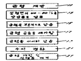
제 1 도는 본 발명의 방법을 수행하는데 있어서의 바람직한 단계들을 나타내는 흐름도.1 is a flow chart showing the preferred steps in carrying out the method of the present invention.
제 2a-c 도는 성형 공정의 여러가지 단계중에 있는 금형의 단면도.Sections 2a-c or cross sectional views of the mold during various stages of the molding process.
제 3 도는 하부 다이의 성형면 상에 장입물이 덮히는 것을 나타내는, 제 2a 도의 선 3-3을 따라 바라본 평면도이다.FIG. 3 is a plan view along line 3-3 of FIG. 2A showing that the charge is covered on the forming surface of the lower die.
[발명의 상세한 설명]Detailed description of the invention
[기술분야][Technical Field]
본 발명은 압출 성형법에 관한 것이며, 보다 더 상세하게는, 진공을 이용하여 장입물(charge)을 압축성형하는 기술에 관한 것이다.TECHNICAL FIELD The present invention relates to an extrusion method, and more particularly, to a technique for compression molding a charge using a vacuum.
[배경기술][Background]
압축 성형법은 금형 공동(空洞)을 형성하는 가열된 상부 및 하부 다이 부재들 사이에 장입물을 배치하여 부품을 성형하는 기술이다. 다음, 다이들은 폐쇄 위치로 이동되고 그 위치에서 다이들이 장입물을 압축함으로써, 장입물이 퍼져 금형 공동을 채우도록 해준다. 수지가 경화된 후, 금형을 열고 완성된 성형품을 꺼낸다.The compression molding method is a technique for forming a part by placing a charge between heated upper and lower die members forming a mold cavity. The dies are then moved to a closed position where the dies compress the charge, allowing the charge to spread to fill the mold cavity. After the resin has cured, the mold is opened and the finished molded product is taken out.
압축 성형기술은 외부 자동차 차체 패널과 같은, 비교적 편평한 표면을 가진 부품을 제조하는데 사용되어왔다. 그러한 부품을 제조하는데 사용되는 장입물은 각종 충전재 및 보강 섬유를 함유하는 열경화성 수지로 이루어지는 것이 보통이다. 종종 그 장입물들은, 당 분야에서 시이트 성형 화합물(SMC)이라 알려진 시이트로 되어 있다. 불행하게도, 유리섬유-보강 플라스틱(FRP)부품을 성형하여 이들이 매우 매끄러운 표면을 갖도록 하는 것은 매우 어려운 일이었다. 제조된 성형품의 표면은 종종 부플음을 갖거나 거칠거나 다공성이다. 그와같은 결함지역은 성형도중 장입물안에 잡힌 공기에 기인하는 것으로 통상 생각된다. 그와같은 포획 공기를 최소로 하기 위한 한가지 노력에 있어서, 비교적 작은 면적의 성형면을 덮는 비교적 두꺼운 장입물을 사용하여, 다이가 닫혀질때 장입물내의 공기를 압착하여 몰아내도록 하는 것이 통상적인 관례이다.Compression molding techniques have been used to make parts with relatively flat surfaces, such as exterior automotive body panels. The charges used to make such parts usually consist of thermosetting resins containing various fillers and reinforcing fibers. Often the contents are made of sheets known in the art as sheet molding compounds (SMC). Unfortunately, it has been very difficult to mold glass fiber-reinforced plastic (FRP) parts so that they have very smooth surfaces. The surface of the formed article is often swelling, rough or porous. Such defect areas are usually thought to be due to air trapped in the charge during molding. In one effort to minimize such trapping air, it is common practice to use a relatively thick charge that covers a relatively small area of the molding surface to squeeze out the air in the charge when the die is closed. .
성형품 표면의 결함 수를 줄이는데 있어서, 압축 성형 공정중에 진공을 이용하는 것이 유용할 수 있다고 인정되었다.[예컨대, 미합중국 특허 제3,840,239호 및 미합중국 특허출원 제488,194호(출원일 : 1993. 4. 25 : 본 출원의 출원인에 양도됨) 참조]. 하지만 그 결과들은 언제나 완전히 만족스러운 것은 아니었다. [고오서치 일행의 "진공 및 다른 성형 변수에 의해 영향을 받는 SMC 성형의 표면 다공성 및 평활도", 플라스틱 공업 협회, 보강 플라스틱/복합물 협의회, 제 33 회 연차 기술 회의(1978년) 9-F 섹숀, 1-7 페이지 참조].In reducing the number of defects on the surface of molded articles, it has been recognized that it may be useful to use a vacuum during the compression molding process. Assigned to the applicant). But the results were not always completely satisfactory. ["The Surface Porosity and Smoothness of SMC Moldings Affected by Vacuum and Other Forming Variables" by KohSearch Group, Plastics Industry Association, Reinforced Plastics / Composites Council, 33rd Annual Technical Conference (1978) 9-F Section, See page 1-7].
보다 더 최근에는, 상업상 허용되는 표면 평활도를 갖는 성형품을 제공하기 위하여 "금형내 코우팅(in-mold coating)"기술이라고 알려진 것이 이 공업분야에서 사용되어 왔다. 이같은 "금형내 코우팅" 기술은, 예컨대 미합중국 특허 제4,081,578호 개시되어 있다. 간단히 말하여, 이 방법은, 경화된 성형품을 금형안에 그대로 두고, 펼쳐져서 표면에 스며드는 조성물로 피복함으로써 그 표면에 있는 홈과 공간을 채우도록하는 추가 처리 단계를 이용한다.More recently, what is known in the art as the "in-mold coating" technique has been used to provide molded articles with commercially acceptable surface smoothness. Such “in-mold coating” techniques are disclosed, for example, in US Pat. No. 4,081,578. In short, the method utilizes an additional processing step that leaves the cured molded product in the mold and spreads and covers it with a composition that penetrates the surface to fill the grooves and spaces on the surface.
불행하게도, 이러한 기술은 몇가지 결점을 갖고 있다. 예컨대, 추가 피복 작동은 귀중한 시간을 소모하고 단일 금형으로부터 얻을 수 있는 생산량을 감소시킨다. 성형품 표면에 대한 피복을 조절하기 위하여 비교적 복잡하고 값비싼 기구들이 이용되어야 하며, 피복물이 성형품 표면에 적절하게 결합되도록 주의를 기울여야만 한다.Unfortunately, this technique has some drawbacks. For example, additional cladding operations consume valuable time and reduce the yield that can be obtained from a single mold. Relatively complex and expensive instruments should be used to control the coating to the molded surface, and care should be taken to ensure that the coating is properly bonded to the molded surface.
당분야에 통상의 지식을 가진자들은 "금형내 코우팅"공정의 사용에 연관된 다른 문제들을 잘 알고 있을 것이다. 그러나, 이같은 문제점들에도 불구하고, 적어도 외부 자동차 차체 패널용으로 상업상 허용되는 성형품을 제공하기 위하여 "금형내 코우팅'을 필요로 한다는 것이 당 공업분야에서는 일반적으로 받아 들여지고 있다.Those skilled in the art will be familiar with other issues related to the use of "in-mold coating" processes. However, in spite of these problems, it is generally accepted in the art that "in-mold coating" is required to provide at least commercially acceptable moldings for exterior automotive body panels.
[발명의 요약][Summary of invention]
본 발명에 따르면, 추가의 "금형내 코우팅"후처리 단계를 필요로 하지 않고서도, 극히 매끄러운 표면처리가된 성형품을 압축 성형시킬 수 있다.According to the present invention, molded articles with extremely smooth surface treatment can be compression molded without the need for additional "in-mold coating" post-treatment steps.
본 발명의 방법은 당 산업분야의 과거의 추세에서 벗어난 것이지만, 그 대신 압축성형 공정중 진공의 이용에 다시금 의존한다. 장입물이 미리 선택된 비율만큼의 금형 표면적을 덮도록 다이들중 어느 한 다이의 성형면위에 장입물을 올려놓음으로써, 완성된 성형품 표면의 거칠음과 요철이 예기치 않게 감소될 수 있다는 것이 밝혀졌다. 장입물은 상부 다이의 성형면과 협력하여 금형 공동을 형성시키는 하부 다이 성형면의 표면적의 40%-80%에 걸쳐 그 하부 다이의 성형면을 덮는 것이 바람직히다.The process of the present invention deviates from past trends in the industry, but instead relies on the use of vacuum during the compression molding process. It has been found that by placing the charge on the forming surface of either die of the die so that the charge covers the mold surface area in a preselected proportion, the roughness and irregularities of the finished molded article surface can be unexpectedly reduced. The charge preferably covers the forming surface of the lower die over 40% -80% of the surface area of the lower die forming surface in cooperation with the forming surface of the upper die.
바람직한 실시예에서는, 먼저, 협력하여 금형 공동을 형성하는 대향된 성형면들이 있는 상부 다이와 하부다이를 갖는 금형이 개방되어 장입물이 하부 다이위에 놓여지도록 한다. 그 장입물은 하부 다이의 성형면 표면적의 40%-80%를 덮도록 배치되는 하나 또는 그 이상의 시이트로 된 SMC 물질로 이루어진다. 다이들은, 금형 공동을 본질적으로 형성하지만 다른 다이가 장입물에서 떨어진채로 있게 되는 부분 폐쇄 위치에 이르도록 서로의 쪽으로 이동된다. 금형 공동은 10초 이하의 시간내에, 바람직하게는 적어도 10인치 Hg(절대)의 진공으로 되도록 배기된다. 금형 공동을 배기시킨 후에, 다이들을 서로의 쪽으로 더 이동시켜 장입물을 압축함으로써, 장입물이 퍼져 금형 공동을 채우도록 한다. 수지는 열과 압력하에서 경화되고, 그러한 경화후 금형을 열고 성형품을 꺼낸다.In a preferred embodiment, first, the mold with the upper die and the lower die with opposed forming surfaces that cooperate to form the mold cavity is opened so that the charge is placed on the lower die. The charge consists of SMC material of one or more sheets arranged to cover 40% -80% of the surface area of the forming surface of the lower die. The dies are moved towards each other to reach a partially closed position that essentially forms the mold cavity but leaves the other die away from the charge. The mold cavity is evacuated to a vacuum of no more than 10 seconds, preferably at least 10 inches of Hg (absolute). After evacuating the mold cavity, the dies are further moved toward each other to compress the charge, causing the charge to spread and fill the mold cavity. The resin is cured under heat and pressure, and after such curing, the mold is opened and the molded article is taken out.
표면의 결함을 제거하는데 있어서, 성형면 상에 장입물이 덮히는 정도가 왜 그렇게 중요한가에 대한 완전한 해석은 내려지지 않았다. 한가지 가능한 설명은, 다이의 성형물상의 장입물 피복정도가 약 40% 이하일 경우에는 두꺼운 장입물이 금형 다이들의 압착하에 퍼질때 유리 섬유가 붕괴되는 경향이 있다는 것이다. 그결과, 유리섬유는 결국 평탄지 않은 배치 또는 유리 밀도를 갖게 되는데, 이는 표면 불균일로 나타나게 된다. 또한, 장입물 피복정도가 너무 낮으면 성형품 둘레에 검은색 얼룩이 때때로 눈에 띤다. 약 80%를 초과하는 높은 피복정도는 유리 섬유 다발을 펴기 위해 요구되는 약간의 이동을 제공하는데 필요한 장입물의 충분한 펴짐을 가능케 하지 못하며, 그로인하여, 성형품이 통상의 페인트 시스템으로 페인트칠이 될 때 "겉으로 드러나는"지역들이 생겨난다. 또한, 성형 공정중에 진공을 이용하면, 붙잡힌 공기에 의해 야기되는 부플음과 홈의 발생이 더 줄어드는 경향이 있다.In removing the defects on the surface, no complete interpretation has been given as to why the extent of the charge on the forming surface is so important. One possible explanation is that if the charge coverage on the die's molding is about 40% or less, the glass fibers tend to collapse when the thick charge spreads under the compression of the mold dies. As a result, the glass fibers eventually have an uneven arrangement or glass density, which results in surface irregularities. In addition, if the coating coverage is too low, black spots sometimes appear around the molded part. Higher coatings, in excess of about 80%, do not allow for sufficient unfolding of the charges necessary to provide the slight movement required to unfold the glass fiber bundles, thereby, when the molding is painted with a conventional paint system. "Outside" areas arise. In addition, the use of vacuum during the molding process tends to further reduce the occurrence of bulging and grooves caused by trapped air.
여하튼, 본 발명의 방법을 이용함으써, 시간 소모를 요하지 않고서도, 그리고 종종, 조절하기 힘든 "금형내 코우팅"후처리 작업을 요하지 않고서도, 매우 매끄러운 표면을 가지는 성형품을 생산해낼 수 있다.In any case, using the method of the present invention, molded articles having very smooth surfaces can be produced without the need for time consuming, and often without the need for difficult to control "in-mold coating" post-treatment operations.
[발명의 최선 실시 형태]Best Mode of the Invention
제 1 도의 단계 11에 나타낸 첫번째의 일반적인 단계는 제 2a 도에 도시된 바와같이 압축 금형(12)을 여는 단계이다. 그 금형(12)은 상부 다이(14)와 하부 다이(16)를 갖는다. 하부 다이(16)는 고정대(도시되어있지 않음)상에 설치되어 있는 반면, 상부 다이(14)는 상하부 다이들 사이의 상대적 이동을 조절하기 위한 램(ram)(20)따위의 작용하에 작동하는 가동 가압판(18)에 연결되어 있다. 다이의 이동을 조절하는 방법은 이 분야에 통상의 지식을 가진자에게 잘 알려져 있는 것으므로 본 명세서에 상술할 필요가 없다.The first general step shown in step 11 of FIG. 1 is to open the compression mold 12 as shown in FIG. 2A. The mold 12 has an upper die 14 and a lower die 16. The lower die 16 is mounted on a fixture (not shown), while the upper die 14 operates under the action of a ram 20 to control the relative movement between the upper and lower dies. It is connected to the
상부 다이(14)는 암(famale) 성형면(22)을 갖는 반면, 하부 다이(16)는 수(male) 성형면(24)을 갖는다. 그 성형면들(22),(24)은 서로 협동하여, 만들어질 성형품의 원하는 모양에 상응하는 모양의 금형 공동을 형성한다. 물론 성형면의 모양은 최종 성형품의 형태에 따라 변경될 수 있다. 그러나, 본 발명은, 표면적이 2평방 피이트(0.186평방미터) 이상인 비교적 크고 일반적으로 편평한 표면의 성형품을 제조하기에 특히 적합한 것이다. 그러한 유형의 성형품에 대한 예로서는, 후드, 덱크 뚜껑, 지붕등과 같은 외부 자동차 차체 패널을 들수 있다. 제 3 도에는, 이러한 유형의 자동차 차체 패널을 성형하기 위해 설게된 하부 다이(16)의 성형면(24)의 윤곽이 도시되어 있다. 본 발명의 목적상, 성형면은 금형 공동을 형성하기 위해 다른쪽 다이 부재의 대향 표면과 협력하는 한쪽 다이 부재의 표면이다.The upper die 14 has a female forming surface 22, while the lower die 16 has a male forming surface 24. The forming surfaces 22, 24 cooperate with each other to form a mold cavity of a shape corresponding to the desired shape of the molded article to be made. Of course, the shape of the molding surface may be changed depending on the shape of the final molded product. However, the present invention is particularly suitable for producing molded articles of relatively large and generally flat surfaces having a surface area of at least two square feet (0.186 square meters). Examples of molded articles of that type include exterior automotive body panels such as hoods, deck lids, roofs, and the like. 3 shows the contour of the forming surface 24 of the lower die 16 designed to form this type of vehicle body panel. For the purposes of the present invention, the forming surface is the surface of one die member which cooperates with the opposing surface of the other die member to form a mold cavity.
열린 위치에서, 상하부 다이(14),(16)는 장입물(26)이 하부 다이(16)의 성형면(24)위에 올려지도록 하는 충분한 거리만큼 떨어져 있게 된다. 이것이 제 1 도에서 단계 13으로 표시되었다.In the open position, the upper and lower dies 14, 16 are spaced apart a sufficient distance to allow the charge 26 to be placed on the forming surface 24 of the lower die 16. This is indicated as step 13 in FIG.
본 발명의 목적상, "장입물(charge)"이라는 용어는, 단단한 고체상태로 경화되는 수지가 포함된 물질을 의미한다. 사용될 수 있는 수지는, 만들어질 복합 제품에 필요한 결합 및 강도를 제공해주는 어떠한 물질이라도 좋다. 대표적인 수지로는 폴리에스테르, 비닐에스테르, 노발락 및 에폭시가 있다. 바람직한 수지물질은 열경화되는 폴리에스테르 수지이다. 본 발명은 시이트 성형 화합물(SMC) 물질로된 하나 또는 그 이상의 시이트 형태로 된 장입물을 압축성형하는데 특히 유용하다. SMC(sheet molding compound) 물질로는, 원하는 모양으로 절단되고 금형내에 배치될 수 있는 반고체 시이트를 형성하기 위해 각종 충전재 및 보강섬유와 혼합된 열경화성 수지가 포함된다. 대표적인 섬유의 예로는, 폴리이미드 섬유, 폴리에스테르 섬유, 폴리아미드 섬유, 천연 섬유 및 금속 섬유가 있다. 바람직한 섬유는 유리섬유 사조(strand) 및 탄소 섬유 사조이다. 현재 가장 바람직한 것은 유리 섬유이다. 시판되고 있는 SMC 물질의 예로써, "A급 2000" SMC(제조원 : 버드 캄파니) ' "퍼미글라스" SMC(제조원 : 프리믹스 인코포레이티드) ; 및 "스무쓰 서페이스" SMC(제조원 : 오웬스 코우닝 파이버 글라스)가 있다.For the purposes of the present invention, the term "charge" means a material comprising a resin that is cured to a solid solid state. The resin that can be used may be any material that provides the necessary bonding and strength to the composite product to be made. Representative resins include polyesters, vinyl esters, Novalak and epoxy. Preferred resin materials are polyester resins which are thermoset. The present invention is particularly useful for compression molding charges in the form of one or more sheets of sheet molding compound (SMC) material. Sheet molding compound (SMC) materials include thermosetting resins mixed with various fillers and reinforcing fibers to form a semisolid sheet that can be cut into a desired shape and placed in a mold. Representative fibers include polyimide fibers, polyester fibers, polyamide fibers, natural fibers and metal fibers. Preferred fibers are glass fiber yarns and carbon fiber yarns. At present the most preferred are glass fibers. Examples of commercially available SMC materials include "Class A 2000" SMC (manufacturer: Bird Company) "Permiglass" SMC (manufacturer: Premix Incorporated); And "Smooth Surface" SMC (Owens Corning Fiberglass).
본 발명은 열경화성 SMC 물질을 사용하는 경우에 특히 적합한 것이지만, 벌크The invention is particularly suitable when using thermoset SMC materials, but in bulk
(bulk)성형 화합물, 두꺼운 성형 화합물 및 XMC 물질(연속섬유 SMC에 대한 "피피지 인더스트리즈"의 상표)과 같은 다른 유형의 장입물을 사용함으로써 우수한 결과가 얻어질 수 있다.Good results can be obtained by using other types of charges such as bulk molding compounds, thick molding compounds and XMC materials (trademark of "Fiji Fiji Industries" for continuous fiber SMC).
제 2a 도와 제 3 도에서, 장입물(26)은 SMC 물질로된 2개의 시이트(28),(32a and 3, the charge 26 is formed of two sheets 28, 3 of SMC material.
0)의 형태를 취한다. 본 발명에 따라, 시이트들(29),(30)은, 장입물이 성형면(24)의 전체 표면의 40%-80%를 덮도록 성형면(24)위에 배치된다. 앞서 기재했던 바와같이, 장입물이 성형면을 40%이하 또는 80%이상 덮는 경우에는 표면 기복이 바람직하지 못하게 증가되며 완성된 성형품은 결함을 갖게 된다. 대부분의 외부 자동차 차체 패널에 있어서, 장입물 피복의 바람직한 범위는 50%-75%이다. 당업자라면 잘 알수 있는 바와같이, 성형면 상의 장입물의 두께, 중량 및 배치는 최종 성형품의 형태에 따라 변경될 수 있다. 일반적으로, 장입물은, 한개 이상의 시이트가 사용되는 경우, 시이트(28),(30) 사이의 약간의 겹침으로 표현되는 바와같이, 개개의 시이트들 사이에 거의 또는 전혀 간격을 두지 않은채 대체로 중앙에 위치되어야 한다. 장입물(26)의 시이트들(28),(30) 각각은, 서로 중첩된 SMC 물질의 1-4매의 시이트(각 시이트의 두께는 약 1/8-1/4인치(0.32-0.64cm)로 구성됨이 바람직하다. 이것은, 6-10매의 시이트들이 표면적의 25%정도만을 덮는 훨씬 더 두꺼운 장입물을 이루는 종래의 몇몇 과정들과 대조되는 것이다.Takes the form 0). According to the invention, the sheets 29, 30 are arranged on the forming surface 24 such that the contents cover 40% -80% of the entire surface of the forming surface 24. As described above, if the charge covers less than 40% or more than 80% of the molded surface, surface relief is undesirably increased and the finished molded article is defective. For most exterior automotive body panels, the preferred range of charge coating is 50% -75%. As will be appreciated by those skilled in the art, the thickness, weight and placement of the charge on the molding surface may vary depending on the shape of the final molded article. Generally, the charge is generally centered with little or no spacing between the individual sheets, as represented by a slight overlap between sheets 28 and 30 when more than one sheet is used. Should be located at The sheets 28 and 30 of the charge 26 each comprise one to four sheets of SMC material superimposed on each other (the thickness of each sheet is about 1 / 8-1 / 4 inch (0.32-0.64 cm). This is in contrast to some of the conventional processes in which 6-10 sheets form a much thicker charge covering only about 25% of the surface area.
단계 15에 표시된 바와같이, 그 다음의 일반적인 단계는 금형을 제 2b 도에서와 같이 부분 폐쇄위치로 이동시키는 것이다. 부분 폐쇄위치에서, 금형 공동(32)은 상하부 다이들에 의해 그 경계가 본질적으로 정해지지만 상부 다이(14)는 장입물(26)로부터 떨어져 유지된다. 또한, 상부 밀봉 호스(40)가 하부 밀봉 링(52)에 접촉될 때, 금형 공동(32)을 둘러싸는 밀폐된 진공실(34)이 형성된다. 부분 폐쇄위치에서 상하부 다이들 사이의 간격은, 진공으로 배기되어야 할 체적을 최소화하기 위하여 가능한한 작게 유지되어야 한다. 수 인치정도의 간격이면 대체로 만족스럽다.As indicated in step 15, the next general step is to move the mold to the partially closed position as in Figure 2b. In the partially closed position, the mold cavity 32 is essentially bounded by upper and lower dies but the upper die 14 is kept away from the charge 26. In addition, when the upper sealing hose 40 is in contact with the lower sealing ring 52, a sealed vacuum chamber 34 surrounding the mold cavity 32 is formed. The spacing between the upper and lower dies in the partially closed position should be kept as small as possible to minimize the volume to be evacuated to vacuum. Intervals of several inches are generally satisfactory.
바람직한 성형 장치에서는 상부 다이(14)를 둘러싸는 환형 링(36)이 포함된다. 이 실시예에서, 환형 링(36)은 그의 아래분분에 일반적으로 수평의 편평한 표면(38)을 가지는 직사각형의 금속관 형태를 취한다. 가요성의 상부 밀봉 호스(40)가 그 표면(38)에 붙어있다. 환형 링(36)은 공기압에 의해 또는 수압에 의해 작용되는 다수의 실린더의 작용하에 상부 다이(14)에 대하여 자유로이 움직인다. 두개의 실린더(42),(44)가 도면에 도시되어 있다. 금형이 열려질때 실린더는 제 2a 도에 점선으로 나타낸 바와같이 신장되는 것이 보통이다. 가요성의 격막 또는 벨로우(bellow)(46)가 그의 안쪽 가장자리에서 플랜지 부재(48)를 통해 상부 다이(14)의 둘레에 단단히 연결되어 있는 한편, 벨로우(46)의 바깥쪽 가장자리는 환형 링(36)으로부터 연장되어 있는 플랜지(50)에 연결되어 있다.In a preferred molding apparatus an annular ring 36 is enclosed surrounding the upper die 14. In this embodiment, the annular ring 36 takes the form of a rectangular metal tube having a generally flat flat surface 38 at its bottom. A flexible top seal hose 40 is attached to its surface 38. The annular ring 36 is free to move relative to the upper die 14 under the action of a plurality of cylinders acted by air pressure or by hydraulic pressure. Two cylinders 42, 44 are shown in the figure. When the mold is opened, the cylinder is usually stretched as indicated by the dashed line in Figure 2a. A flexible diaphragm or bellows 46 is securely connected around the upper die 14 via the flange member 48 at its inner edge, while the outer edge of the bellows 46 is annular ring 36. It is connected to the flange 50 extended from).
제 2b 도에 도시된 위치에 도달하기 위하여, 램(20)이 작동되어 상부 밀봉 호스(40)가 하부 밀봉 링(52)에 접촉되는 부분 폐쇄위치로 상부 다이(14)를 이동시킨다. 그리하여, 진공실(34)은 상부 다이(14), 벨로우(46), 환형 링(36), 압축 시일(seal)로 작용하는 상부 밀봉 호스(40), 중공의 관(54) 및 하부 다이(16)에 의하여 경계가 정해진다. 실린더(42),(44)에 의해 제공된 아래로 향하는 힘은, 금형 공동(32)둘레가 일관되게 잘 밀봉되도록 작용해준다. 또한, 실린더를 사용하여 상부 다이(14)에 대하여 환형 링(36)을 위쪽으로 이동시킴으로써(제 2a 도에 도시되어 있음), 세척 및 설치를 위한 목적으로 그리고 용이한 접근이 요구되는 다른 이유로 인하여 상부 다이에 손쉽게 접근할 수 있게 해줄 수 있다.To reach the position shown in FIG. 2B, the ram 20 is actuated to move the upper die 14 to a partially closed position where the upper sealing hose 40 contacts the lower sealing ring 52. Thus, the vacuum chamber 34 includes an upper die 14, a bellows 46, an annular ring 36, an upper sealing hose 40 acting as a compression seal, a hollow tube 54 and a lower die 16. Is bounded by The downward force provided by the cylinders 42 and 44 acts to seal the mold cavity 32 consistently well. In addition, by using the cylinder to move the annular ring 36 upward relative to the upper die 14 (shown in FIG. 2A), for cleaning and installation purposes and for other reasons that require easy access. This allows for easy access to the upper die.
진공실(34)이 밀봉된 후, 제 1 도의 단계 17에 표시된 바와같이 금형 공동을 배기시키는 단계가 수행된다. 만족스러운 결과는, 금형 공동(32)속의 진공을 10초 이하의 시간내에 적어도 10인치 Hg(절대)로 만듦으로써 얻어질 수 있다. 그러나, 다이들이 그들의 부분 폐쇄위치에 도달한 후, 5초 이내에 5인치 Hg의 진공으로 만드는 것이 바람직하다. 이것은, 밸브(62)를 통하여 진공실(34)에 연결되어 있는 진공원(60)에 의하여 달성될 수 있다. 진공원(60)은 진공실(34)에 연속적으로 연결되어 있는 다수의 미리 배기된 탱크(도시되어 있지 않음)로 구성되는 것이 바람직하다. 비교적 큰 파이프(64)가 하부 밀봉 링(52)의 내측 표면 부위상에 다수의 구멍(66)을 가지는 중공의 관(54)에 연결된다. 따라서 진공 탱크와 진공실(34)사이에서 유체 소통이 이루어진다. 중공의 관(54)을 진공 밀봉 구조물의 일부로서 사용하고 진공을 끌어내기 위한 비교적 큰 도관으로서 사용하는 이중 용도는 특히 유익하다.After the vacuum chamber 34 is sealed, the step of evacuating the mold cavity is performed as indicated in step 17 of FIG. Satisfactory results can be obtained by making the vacuum in the mold cavity 32 at least 10 inches Hg (absolute) in less than 10 seconds. However, after the dies have reached their partially closed position, it is desirable to make a vacuum of 5 inches Hg within 5 seconds. This may be accomplished by the vacuum source 60 being connected to the vacuum chamber 34 via the valve 62. The vacuum source 60 preferably consists of a number of pre-vented tanks (not shown) that are continuously connected to the vacuum chamber 34. A relatively large pipe 64 is connected to the hollow tube 54 having a plurality of holes 66 on the inner surface portion of the lower seal ring 52. Thus, fluid communication occurs between the vacuum tank and the vacuum chamber 34. The dual use of using hollow tubes 54 as part of the vacuum sealing structure and as a relatively large conduit for drawing vacuum is particularly advantageous.
금형 공동이 배기된 후, 상부 다이를 다이들의 완전 폐쇄위치를 향해 이동시킨다. 금형 폐쇄 단계중에, 상부 다이가 장입물(26)과 접촉함으로써 장입물이 퍼져 금형 공동(34)을 채우게 된다. 상부 다이가 밑으로 이동하는 중에 부분 폐쇄위치에서 완전히 정지할 필요가 없는데, 왜냐하면, 그러한 것은 대형 프레스에서는 실용적일 수 없기 때문이다. 필요한 것은, 상부 다이가 장입물과 접촉하기 전에 진공실이 밀봉되고 배기되는 것뿐이다. 장입물(26)내의 수지가 열경화성 타입인 경우에는, 상하부 다이를 가열하기 위한 수단(도시되어 있지 않음)이 제공된다. 대표적인 SMC 장입물의 경우, 다이는 140-160℃로 가열되어야 하는데, 이때 다이들은 500-1500psi의 성형압력을 제공한다.After the mold cavity is evacuated, the upper die is moved towards the fully closed position of the dies. During the mold closing step, the upper die contacts the charge 26 to spread the charge to fill the mold cavity 34. It is not necessary to stop completely in the partially closed position while the upper die is moving down, because such may not be practical in large presses. All that is needed is for the vacuum chamber to be sealed and evacuated before the upper die contacts the charge. When the resin in the charge 26 is of the thermosetting type, a means (not shown) for heating the upper and lower dies is provided. For a typical SMC charge, the die should be heated to 140-160 ° C. where the dies provide a forming pressure of 500-1500 psi.
금형이 일단 제 2c 도에 도시된 바와같은 완전 폐쇄위치에 도달되면, 금형 공동은 대기압으로 복귀될 수 있다. 이는, 밸브(62)를 폐쇄하고 대기압에 연결되어 있는 밸브(72)를 개방시킴으로써 달성될 수 있다. 밸브(62)가 닫힌때 진공 펌프에 의하여 진공 탱크가 배기되어 다음번 성형 주기의 준비를 시작할 수 있다.Once the mold has reached the fully closed position as shown in Figure 2c, the mold cavity can be returned to atmospheric pressure. This can be accomplished by closing the valve 62 and opening the valve 72 which is connected to atmospheric pressure. When the valve 62 is closed, the vacuum tank is evacuated by the vacuum pump to begin preparation for the next molding cycle.
수지가 일단 경화되면, 금형을 열어 성형품을 꺼낸다(제 1 도의 단계 23). SMC 장입물의 경우, 경화시간은 성형품의 두께 각 1/8인치(0.32cm)에 대하여 1-3분인 것이 전형적이다.Once the resin has cured, the mold is opened to remove the molded article (step 23 in FIG. 1). For SMC charges, the cure time is typically 1-3 minutes for each 1/8 inch (0.32 cm) of thickness of the molded article.
본 발명에 따라 제조된 성형품은 현저한 표면 평활도를 나타냄과 동시에, 일반적으로 허용되는 성형품을 제공하기 위하여 "금형내 코우팅"단계의 사용을 필요로 하지 않는 정도로까지 홈과 부플음이 최소화된다. 따라서, 금형내 코우팅 공정에 관련된 추가의 비용과 난점들이 배제될 수 있다.Molded articles made in accordance with the present invention exhibit significant surface smoothness, while at the same time minimizing grooves and bulging to the extent that they do not require the use of an "in-mold coating" step to provide acceptable moldings. Thus, additional costs and difficulties associated with in-mold coating processes can be eliminated.
Claims (6)
Applications Claiming Priority (3)
| Application Number | Priority Date | Filing Date | Title |
|---|---|---|---|
| US06/640,470 US4612149A (en) | 1983-04-25 | 1984-08-13 | Compression molding a charge using vacuum |
| US640470 | 1984-08-31 | ||
| PCT/US1985/001438 WO1986001148A1 (en) | 1984-08-13 | 1985-07-31 | Compression molding a charge using vacuum |
Publications (2)
| Publication Number | Publication Date |
|---|---|
| KR860700233A KR860700233A (en) | 1986-08-01 |
| KR920004045B1 true KR920004045B1 (en) | 1992-05-23 |
Family
ID=24568393
Family Applications (1)
| Application Number | Title | Priority Date | Filing Date |
|---|---|---|---|
| KR1019860700205A KR920004045B1 (en) | 1984-08-13 | 1985-07-31 | Composition molding a charge using vacuum |
Country Status (11)
| Country | Link |
|---|---|
| US (1) | US4612149A (en) |
| EP (1) | EP0189471B1 (en) |
| JP (1) | JPS61502951A (en) |
| KR (1) | KR920004045B1 (en) |
| AU (1) | AU564887B2 (en) |
| BR (1) | BR8506876A (en) |
| CA (1) | CA1254712A (en) |
| DE (1) | DE3580466D1 (en) |
| ES (1) | ES8703327A1 (en) |
| MX (1) | MX166834B (en) |
| WO (1) | WO1986001148A1 (en) |
Cited By (1)
| Publication number | Priority date | Publication date | Assignee | Title |
|---|---|---|---|---|
| KR101156900B1 (en) * | 2010-10-26 | 2012-06-21 | 금호타이어 주식회사 | semi curing processing device for body sheet in tire manufacturing process |
Families Citing this family (36)
| Publication number | Priority date | Publication date | Assignee | Title |
|---|---|---|---|---|
| CA1267763A (en) * | 1986-03-19 | 1990-04-17 | Kenneth A. Iseler | Vacuum compression molding method using preheated charge |
| US4867924A (en) * | 1988-04-22 | 1989-09-19 | The Budd Company | Method and apparatus for compression molding under vacuum |
| JPH069828B2 (en) * | 1988-08-26 | 1994-02-09 | 三ツ星ベルト株式会社 | Method for manufacturing power transmission belt and vulcanizing flexible jacket used in the method |
| US5001000A (en) * | 1988-09-26 | 1991-03-19 | E. I. Du Pont De Nemours And Company | Process for forming a composite structure of thermoplastic polymer and sheet molding compound |
| US4959189A (en) * | 1988-09-26 | 1990-09-25 | E. I. Du Pont De Nemours And Company | Process for forming a composite structure of thermoplastic polymer and sheet molding compound |
| US5000997A (en) * | 1989-02-06 | 1991-03-19 | The Budd Company | Method for making a painted part and part made thereby |
| US5188783A (en) * | 1990-02-20 | 1993-02-23 | Hughes Aircraft Company | Method of making articles containing an ion-conductive polymer |
| US5268400A (en) * | 1990-07-19 | 1993-12-07 | The Budd Company | Flexible sheet molding compound and method of making the same |
| US5100935A (en) * | 1990-07-19 | 1992-03-31 | The Budd Company | Flexible sheet molding compound and method of making the same |
| US5298212A (en) * | 1991-01-16 | 1994-03-29 | Surface Technologies, Inc. | Method for forming a laminated substrate |
| GB2272397A (en) * | 1992-10-14 | 1994-05-18 | Lotus Car | Moulding method and apparatus |
| ES2108602B1 (en) * | 1994-01-19 | 1998-07-16 | Hispano Mecano Electrica Sa | IMPROVEMENTS IN THE PROCEDURES FOR MOLDING POLYESTER AND SIMILAR. |
| JP3423766B2 (en) * | 1994-03-11 | 2003-07-07 | Towa株式会社 | Resin encapsulation molding method and mold device for electronic components |
| US6106274A (en) * | 1995-08-30 | 2000-08-22 | The Budd Company | Molding apparatus with charge overflow |
| US5753164A (en) * | 1995-08-30 | 1998-05-19 | The Budd Company | Automated thermoset molding method |
| US5853857A (en) * | 1997-02-20 | 1998-12-29 | The Budd Company | Windshield frame |
| US6146578A (en) * | 1997-10-09 | 2000-11-14 | Lear Corporation | Method for molding headliners |
| US6103150A (en) * | 1998-03-11 | 2000-08-15 | The Budd Company | Molding overflow feedback method |
| US6264454B1 (en) | 1998-03-11 | 2001-07-24 | The Budd Company | Wrapped SMC charge method and apparatus |
| US6103032A (en) * | 1998-04-24 | 2000-08-15 | The Budd Company | Sheet molding compound manufacturing improvements |
| US6119750A (en) * | 1998-04-24 | 2000-09-19 | The Budd Company | Sheet molding compound manufacturing improvements |
| US6533976B1 (en) * | 2000-03-07 | 2003-03-18 | Northrop Grumman Corporation | Method of fabricating ceramic matrix composites employing a vacuum mold procedure |
| KR100356860B1 (en) * | 2000-09-05 | 2002-10-18 | 현대자동차주식회사 | manufacturing method for door latch plate |
| US6805546B2 (en) * | 2001-10-24 | 2004-10-19 | Thyssenkrupp Budd Company | Vacuum assisted molding apparatus |
| US20050182205A1 (en) * | 2004-02-17 | 2005-08-18 | Guha Probir K. | Polymeric thickener for molding compounds |
| US7829637B2 (en) * | 2004-02-17 | 2010-11-09 | Continental Structural Plastics | Polymeric thickener for molding compounds |
| US8127691B2 (en) * | 2004-03-03 | 2012-03-06 | Fitzpatrick Technologies, Llc | SMC pallet |
| US20060081158A1 (en) * | 2004-10-19 | 2006-04-20 | Fitzpatrick Technologies, L.L.C. | Pultrusion pallet |
| US20060220273A1 (en) * | 2005-03-29 | 2006-10-05 | Armstrong Bradford D | Process for compression moulding liquid resins with structural reinforcements |
| US20070017423A1 (en) * | 2005-07-19 | 2007-01-25 | Ingham Terry L | Pallet With Recycled Components |
| US20070017422A1 (en) * | 2005-07-19 | 2007-01-25 | Fitzpatrick Technologies, Llc | Pallet with composite components |
| US8261673B2 (en) * | 2007-09-26 | 2012-09-11 | Fitzpatrick Technologies | Pallet with lead board |
| CN103965792B (en) * | 2013-01-29 | 2018-11-09 | 康廷南拓结构塑料有限公司 | Air adhering method |
| CN103963318B (en) | 2013-01-29 | 2019-08-09 | 康廷南拓结构塑料有限公司 | The vacuum forming method of thermosetting property sheet-like article |
| CH712377B1 (en) | 2016-04-20 | 2019-10-15 | Primcut Ag | Banderole for baked goods. |
| GB201610865D0 (en) * | 2016-06-22 | 2016-08-03 | Composite Tech And Applications Ltd | An apparatus for manufacturing a composite component |
Family Cites Families (8)
| Publication number | Priority date | Publication date | Assignee | Title |
|---|---|---|---|---|
| US3957943A (en) * | 1971-11-09 | 1976-05-18 | Nippon Gakki Seizo Kabushiki Kaisha | Method for producing glass fiber reinforced plastic molded articles with decorative patterns and article produced thereby |
| US3840239A (en) * | 1972-10-26 | 1974-10-08 | Gen Tire & Rubber Co | Compression molding in a vacuum and seal for use therein |
| US4081578A (en) * | 1974-06-27 | 1978-03-28 | The General Tire & Rubber Company | In-mold coating composition and method of applying same |
| US4081548A (en) * | 1975-11-18 | 1978-03-28 | Merck & Co., Inc. | Antibiotics |
| US4353857A (en) * | 1980-02-01 | 1982-10-12 | Ford Motor Company | Method for making plastic panel and panel |
| JPS581522A (en) * | 1981-06-25 | 1983-01-06 | Sekisui Chem Co Ltd | Preparation of frp |
| JPS6036417Y2 (en) * | 1982-11-22 | 1985-10-29 | 株式会社内藤製作所 | Vulcanization molding equipment |
| US4488862A (en) * | 1983-04-25 | 1984-12-18 | The Budd Company | Compression molding apparatus having vacuum chamber |
-
1984
- 1984-08-13 US US06/640,470 patent/US4612149A/en not_active Expired - Lifetime
-
1985
- 1985-07-18 CA CA000487067A patent/CA1254712A/en not_active Expired
- 1985-07-31 KR KR1019860700205A patent/KR920004045B1/en not_active IP Right Cessation
- 1985-07-31 EP EP85903947A patent/EP0189471B1/en not_active Expired - Lifetime
- 1985-07-31 JP JP60503439A patent/JPS61502951A/en active Granted
- 1985-07-31 AU AU46385/85A patent/AU564887B2/en not_active Ceased
- 1985-07-31 BR BR8506876A patent/BR8506876A/en not_active IP Right Cessation
- 1985-07-31 WO PCT/US1985/001438 patent/WO1986001148A1/en active IP Right Grant
- 1985-07-31 DE DE8585903947T patent/DE3580466D1/en not_active Expired - Fee Related
- 1985-08-12 ES ES546075A patent/ES8703327A1/en not_active Expired
- 1985-08-13 MX MX206271A patent/MX166834B/en unknown
Cited By (1)
| Publication number | Priority date | Publication date | Assignee | Title |
|---|---|---|---|---|
| KR101156900B1 (en) * | 2010-10-26 | 2012-06-21 | 금호타이어 주식회사 | semi curing processing device for body sheet in tire manufacturing process |
Also Published As
| Publication number | Publication date |
|---|---|
| JPH0329576B2 (en) | 1991-04-24 |
| AU564887B2 (en) | 1987-08-27 |
| EP0189471A1 (en) | 1986-08-06 |
| ES546075A0 (en) | 1987-02-16 |
| BR8506876A (en) | 1986-12-09 |
| WO1986001148A1 (en) | 1986-02-27 |
| JPS61502951A (en) | 1986-12-18 |
| AU4638585A (en) | 1986-03-07 |
| KR860700233A (en) | 1986-08-01 |
| ES8703327A1 (en) | 1987-02-16 |
| EP0189471A4 (en) | 1987-10-27 |
| CA1254712A (en) | 1989-05-30 |
| EP0189471B1 (en) | 1990-11-07 |
| US4612149A (en) | 1986-09-16 |
| DE3580466D1 (en) | 1990-12-13 |
| MX166834B (en) | 1993-02-08 |
Similar Documents
| Publication | Publication Date | Title |
|---|---|---|
| KR920004045B1 (en) | Composition molding a charge using vacuum | |
| US5130071A (en) | Vacuum compression molding method using preheated charge | |
| US4855097A (en) | Compression molding a charge using vacuum | |
| US4488862A (en) | Compression molding apparatus having vacuum chamber | |
| US4551085A (en) | Compression molding apparatus having vacuum chamber | |
| CA2170106C (en) | Resin transfer molding process | |
| US5526767A (en) | Method of manufacturing a boat hull | |
| US4267142A (en) | Reinforced resin molding method and apparatus | |
| US3135640A (en) | Process of and an apparatus for manufacturing hollow articles from reinforced synthetic resins | |
| AU636418B2 (en) | Reaction injection molding apparatus for forming fiber-resin forced molded article | |
| US4946640A (en) | Method for forming preformed material | |
| CA1128846A (en) | Reinforcing a layer of plastics material | |
| US3140325A (en) | Manufacture of molded bodies | |
| US8118961B2 (en) | Method of manufacturing a Z-section component from composite material | |
| GB2432336A (en) | Production of composite mouldings | |
| US3368239A (en) | Apparatus for molding impregnated glass fiber articles | |
| US3272672A (en) | Method and apparatus for pressure laminating tape wound articles | |
| EP0431729A2 (en) | Panels faced with glass reinforced plastics | |
| CA1217018A (en) | Compression molding apparatus having vacuum chamber | |
| JP3050700B2 (en) | Method of manufacturing box-shaped resin molded product | |
| ATE29424T1 (en) | METHOD OF MAKING HIGH PRESSURE COMPOSITE RING FLANGES AND THE PRODUCT PRODUCED. | |
| GB1584687A (en) | Production of articles moulded from plastics | |
| CN110722815A (en) | Modularized forming process of light high-strength carbon fiber portable box | |
| GB2272397A (en) | Moulding method and apparatus |
Legal Events
| Date | Code | Title | Description |
|---|---|---|---|
| A201 | Request for examination | ||
| E902 | Notification of reason for refusal | ||
| G160 | Decision to publish patent application | ||
| E701 | Decision to grant or registration of patent right | ||
| GRNT | Written decision to grant | ||
| FPAY | Annual fee payment |
Payment date: 20000518 Year of fee payment: 9 |
|
| LAPS | Lapse due to unpaid annual fee |