KR920002608B1 - Audio reproduction device with head base moving mechanism - Google Patents
Audio reproduction device with head base moving mechanism Download PDFInfo
- Publication number
- KR920002608B1 KR920002608B1 KR1019890003253A KR890003253A KR920002608B1 KR 920002608 B1 KR920002608 B1 KR 920002608B1 KR 1019890003253 A KR1019890003253 A KR 1019890003253A KR 890003253 A KR890003253 A KR 890003253A KR 920002608 B1 KR920002608 B1 KR 920002608B1
- Authority
- KR
- South Korea
- Prior art keywords
- gear
- lever
- cam
- pose
- head base
- Prior art date
Links
Images


Classifications
-
- G—PHYSICS
- G11—INFORMATION STORAGE
- G11B—INFORMATION STORAGE BASED ON RELATIVE MOVEMENT BETWEEN RECORD CARRIER AND TRANSDUCER
- G11B15/00—Driving, starting or stopping record carriers of filamentary or web form; Driving both such record carriers and heads; Guiding such record carriers or containers therefor; Control thereof; Control of operating function
- G11B15/675—Guiding containers, e.g. loading, ejecting cassettes
- G11B15/67502—Details
- G11B15/67505—Servo control
-
- G—PHYSICS
- G11—INFORMATION STORAGE
- G11B—INFORMATION STORAGE BASED ON RELATIVE MOVEMENT BETWEEN RECORD CARRIER AND TRANSDUCER
- G11B15/00—Driving, starting or stopping record carriers of filamentary or web form; Driving both such record carriers and heads; Guiding such record carriers or containers therefor; Control thereof; Control of operating function
- G11B15/18—Driving; Starting; Stopping; Arrangements for control or regulation thereof
- G11B15/1883—Driving; Starting; Stopping; Arrangements for control or regulation thereof for record carriers inside containers
-
- G—PHYSICS
- G11—INFORMATION STORAGE
- G11B—INFORMATION STORAGE BASED ON RELATIVE MOVEMENT BETWEEN RECORD CARRIER AND TRANSDUCER
- G11B15/00—Driving, starting or stopping record carriers of filamentary or web form; Driving both such record carriers and heads; Guiding such record carriers or containers therefor; Control thereof; Control of operating function
- G11B15/18—Driving; Starting; Stopping; Arrangements for control or regulation thereof
- G11B15/44—Speed-changing arrangements; Reversing arrangements; Drive transfer means therefor
- G11B15/442—Control thereof
-
- G—PHYSICS
- G11—INFORMATION STORAGE
- G11B—INFORMATION STORAGE BASED ON RELATIVE MOVEMENT BETWEEN RECORD CARRIER AND TRANSDUCER
- G11B25/00—Apparatus characterised by the shape of record carrier employed but not specific to the method of recording or reproducing, e.g. dictating apparatus; Combinations of such apparatus
- G11B25/06—Apparatus characterised by the shape of record carrier employed but not specific to the method of recording or reproducing, e.g. dictating apparatus; Combinations of such apparatus using web-form record carriers, e.g. tape
- G11B25/063—Apparatus characterised by the shape of record carrier employed but not specific to the method of recording or reproducing, e.g. dictating apparatus; Combinations of such apparatus using web-form record carriers, e.g. tape using tape inside container
-
- G—PHYSICS
- G11—INFORMATION STORAGE
- G11B—INFORMATION STORAGE BASED ON RELATIVE MOVEMENT BETWEEN RECORD CARRIER AND TRANSDUCER
- G11B5/00—Recording by magnetisation or demagnetisation of a record carrier; Reproducing by magnetic means; Record carriers therefor
- G11B5/48—Disposition or mounting of heads or head supports relative to record carriers ; arrangements of heads, e.g. for scanning the record carrier to increase the relative speed
- G11B5/54—Disposition or mounting of heads or head supports relative to record carriers ; arrangements of heads, e.g. for scanning the record carrier to increase the relative speed with provision for moving the head into or out of its operative position or across tracks
Abstract
내용 없음.No content.
Description
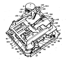
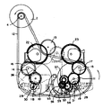
제1도는 본 발명에 의한 음향재생장치의 사시도.1 is a perspective view of a sound reproducing apparatus according to the present invention.
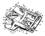
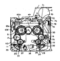
제2도는 다른 방향에서 본 사시도.2 is a perspective view from another direction.
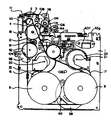
제3도는저부 커버를 제거한 상태의 저면도.3 is a bottom view with the bottom cover removed.
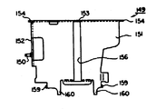
제4도는 이젝트 완료상태를 나타낸 평면도.4 is a plan view showing the completion state of the eject.
제5도는 이젝트 동작전의 상태를 나타낸 평면도.5 is a plan view showing a state before an ejection operation.
제6도는 제5도의 측면도.6 is a side view of FIG.
제7도는 제4도의 측면도.7 is a side view of FIG.
제8도 내지 제10도는 구동모터의 전달 경로부분을 설명하는 것으로서, 제8도는 구동모터가 반시계 회전 방향에서의 파워 어시스트 동작을 나타낸 요부 저면도.8 to 10 illustrate the transmission path portion of the drive motor, and FIG. 8 is a bottom view of the main part of the drive motor in which the power assist operation in the counterclockwise rotation direction is shown.
제9도는 구동모터가 시계회전 방향에서의 파워 어시스트 동작을 나타내는 요부 저면도.Fig. 9 is a bottom view of the main part of the drive motor in which the power assist operation in the clockwise direction is shown;
제10도는 구동모터와 랙이 전달상태에 있는 요부 저면도.10 is a bottom view of the main part in which the drive motor and the rack are in a delivered state.
제11도 및 제12도는 셀렉트레버가 우위치 혹은 좌위치에 있는 상태를 나타낸 요부 저면도.11 and 12 are bottom views showing the main parts of the select lever in a right position or a left position.
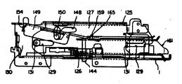
제13도 내지 제16도는 이젝트동작에 있어서의 헤드베이스의 후퇴 동작을 설명하는 것으로서, 제13도는 FWD주행에서의 플레이(PLAY)상태를 나타낸 요부 평면도.13 to 16 illustrate the retraction operation of the head base in the eject operation, and FIG. 13 is a plan view of the main portion showing the play state in the FWD driving.
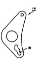
제14도는 이젝트 동작의 도중을 나타낸 요부 평면도.14 is a plan view of the main portion showing the middle of the eject operation;
제15도는 이젝트완료상태를 나타낸 요부 평면도.Figure 15 is a plan view of the main part showing the ejection completion state.
제16도는 제13도의 상태로부터 키이오프(KEY OFF)되었을 때의 요부 평면도.FIG. 16 is a plan view of the principal parts when the key is turned off from the state shown in FIG.
제17도는 FWD주행에 있어서의 플레이 상태를 나타낸 요부 평면도.Fig. 17 is a plan view showing the principal parts of the play state in FWD driving.
제18도는 헤드베이스를 후퇴시킨 상태를 나타낸 요부평면도.18 is a plan view of the main portion showing the state in which the head base is retracted.
제19도는 FF동작을 설명하기 위한 요부 평면도.19 is a plan view of principal parts for explaining the FF operation.
제20도는 RWD주행에 있어서의 플레이 상태를 나타낸 요부 평면도.Fig. 20 is a plan view showing the principal parts of the play state in the RWD driving.
제21도는 샤시의 저면도.21 is the bottom view of the chassis.
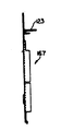
제22도는 포즈레버의 정면도.22 is a front view of a pose lever.
제23도는 유성기어를 설치한 회동편의 정면도.23 is a front view of a pivoting piece provided with planetary gears.
제24도는 핀치레버의 정면도.24 is a front view of the pinch lever.
제25는 셀렉트레버의 정면도.25th is a front view of a select lever.
제26도는 제1의 서브베이스의 정면도.26 is a front view of the first sub-base.
제27도는 제2의 서브베이스의 정면도.27 is a front view of the second sub-base.
제28도는 헤드베이스의 정면도.28 is a front view of the head base.
제29도 및 제30도는 측판의 평면도 및 측면도.29 and 30 are plan and side views of the side plates;
제31도는 클러치레버의 정면도.31 is a front view of the clutch lever.
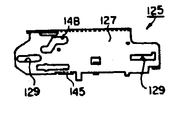
제32도 및 제33도는 이젝트레버의 측면도 및 평면도.32 and 33 are side and plan views of the eject lever.
제34도는 플레이트 베이스의 평면도.34 is a top view of the plate base.
제35도 및 제36도는 홀더 프레임의 평면도 및 측면도.35 and 36 are top and side views of the holder frame.
제37도 내지 제40도는 카세트 홀더의 평면도, 정면도 및 좌우 측면도.37 to 40 are top, front and left and right side views of the cassette holder.
제41도 및 제42도는 저부카버의 저면도 및 측면도.41 and 42 are bottom and side views of the bottom cover.
제43도 및 제44도는 제1 및 제2의 이젝트아암의 조립상태를 나타낸 평면도 및 측면도이다.43 and 44 are plan and side views showing the assembled state of the first and second ejector arms.
* 도면의 주요부분에 대한 부호의 설명* Explanation of symbols for main parts of the drawings
1 : 샤시 2 : 구동모터1: Chassis 2: Drive motor
4 : 풀리 5 : 소기어4: pulley 5: small gear
6, 7 : 캡스턴축 8, 9 : 플라이 휠6, 7:
10, 11 : 기어 12 : 벨트10, 11: gear 12: belt
14, 15 : 핀치레버 16, 17 ; 기어14, 15: pinch levers 16, 17; Gear
18, 19 : 캠구멍 22, 23 : 릴 기어18, 19:
26, 27 : 핀치롤러 30, 31 : 회동축26, 27:
36 : 셀렉트레버 37, 38 ; 이접 캠구멍36:
53 : 셀렉트핀 54 : 회동편53: select pin 54: rotating part
55 : 기어 56 : 소기어55: gear 56: small gear
58 : 유성기어 59 : 호상기어58: planetary gear 59: whistle gear
62 : 자기헤드 63 : 헤드베이스62: magnetic head 63: head base
63a : FF록용 구멍 63d : 솔레노이드레버63a: hole for FF
63f : 솔레노이드 68, 69 : 삽통구멍63f:
70 : 롤러 72 : 제1의 서브베이스70: roller 72: first sub-base
74 : 제2의 서브베이스 75 : 가이트핀74: second subbase 75: guide pin
78 : 코일스프링 82 : 소기어78: coil spring 82: small gear
83 : 포즈레버 89 : 스토퍼편83: pose lever 89: stopper
91 : 기어 84 : 요동치차91: gear 84: swing gear
86, 87 : 단연(端緣) 92 : 포즈기어86, 87: by far 92: pose gear
95 : 계지 캠 97 : 단부(段部)95: locking cam 97: end
98 : 플레이레버 99 : 스토퍼 래치(凡)98: play lever 99: stopper latch (凡)
105 : 솔레노이드 106 : 클러치레버105: solenoid 106: clutch lever
110 : 이젝트 솔레노이드 120 : 록레버110: eject solenoid 120: lock lever
124 : 랙구동용 소기어 125 : 이젝트레버124: small gear for driving the rack 125: eject lever
126 : 랙 136 : 제1의 이젝트아암126: rack 136: first ejection arm
138 : 제2의 이젝트아암 146 : 후퇴 캠138: second ejector arm 146: retraction cam
149 : 프레이트베이스 161 : 카세트 홀더149: plate base 161: cassette holder
166 : 창부(窓部)166: window
본 발명은 음향재생장치에 관한 것으로, 특히 오토리버스 기구를 구비한 음향재생장치에 관한 것이다.The present invention relates to a sound reproducing apparatus, and more particularly, to a sound reproducing apparatus having an autoreverse mechanism.
일반적으로, 승용차 등의 차량에 탑재되어 있는 음향재생장치는, 테이프 카세트를 절반 정도만 삽입하기만 하면 카세트가 자동적으로 연주위치에 세트되어 연주상태가 된다. 그리고 테이프가 종단이 오면, 자동적으로 테이프의 종단을 검출하여 지금까지의 캡스턴축에 테이프를 압접하고 있던 핀치롤러를 떨어지게 하고, 역전하고 있는 다른 캡스턴축에 다른 핀치롤러를 압접시켜, 이들의 사이에 테이프를 끼워넣어 이 테이프를 역송하여, 그 연주를 계속시키는 소위 오토리버스 기구를 구비하고 있다.In general, in a sound reproducing apparatus mounted on a vehicle such as a passenger car, the cassette is automatically set at the playing position and enters the playing state only by inserting the tape cassette about halfway. When the tape comes to an end, the end of the tape is automatically detected and the pinch roller that has been press-bonded to the capstan shaft so far falls, and another pinch roller is pressed against another inverted capstan shaft, The so-called autoreverse mechanism which inserts a tape and conveys this tape and continues the performance is provided.
또, 캡스턴축과 핀치롤러의 압점을 떨어지게 하고 릴기구의 회전을 빠르게 하여 테이프를 권취하는 빠른 이송(FF)동작 및 되감기(REW)동작, 혹은 재생음을 내면서 빠른 이송을 하는 빠른 이송재생(REVEW)동작등이 행해지게 되어 있다. 그리고, 이들의 기구 및 동작은 일방향으로만 회전하는 구동모터의 회전을 여러가지의 기어기구, 캠기구 등의 수단을 구비함으로써 행해지도록 구성되어 있었다.In addition, the rapid feed (FF) and rewind (REW) motions of winding the tape by reducing the pressure point of the capstan shaft and the pinch roller and speeding up the reel mechanism, or the rapid feed playback (REVEW) for fast feed with a reproducing sound. Actions are to be performed. In addition, these mechanisms and operations were configured to include rotation of the drive motor which rotates in only one direction by means of various gear mechanisms and cam mechanisms.
그런데, 상기 종래 기술에서는, 구동모터가 일방향으로 밖에 회전되지 아니하므로, 각종 동작을 행하는데 여러가지의 기어 및 캠기구가 필요하고 필연적으로 구조가 복잡하게 되어, 제조, 조립이 곤란하고, 제조 가격이 높아졌었다. 또, 기구가 복잡하기 때문에 고장을 일으킬 염려도 있고 보수비도 높아졌다. 그러므로, 본 발명은 상기 종래 기술의 문제점을 감안하여, 이것을 해결하기 위하여 이루어진 것으로서, 그 목적은, 구동모터를 정역전 가능하게 하고, 동작기구를 간소화하여 제조 가격을 저감할 수 있는 음향재생장치를 제공하는데 있다.However, in the prior art, since the drive motor is rotated only in one direction, various gears and cam mechanisms are necessary to perform various operations, and inevitably become complicated in structure, making manufacturing and assembly difficult, It was high. In addition, because of the complexity of the mechanism, there is a risk of failure and maintenance costs are high. Therefore, the present invention has been made in view of the above-mentioned problems of the prior art, and an object thereof is to provide an acoustic reproducing apparatus capable of reversing the driving motor, simplifying the operation mechanism, and reducing the manufacturing cost. To provide.
상기 목적을 달성하기 위하여, 본 발명은 정회전 혹은 역회전 가능한 모터와, 그 모터에 의하여 동작되고, 자기헤드를 설치한 헤드베이스를 전진시키는 자기헤드 전진기구와, 전진한 자기헤드를 플레이 위치에서 유지하는 유지기구와, 그유지기구를 록하는 스토퍼기구부와, 상기 헤드베이스와의 사이에 배치한 탄성부재와, 카세트의 이젝트 동작시에 상기 헤드베이스에 계합되어 강제 후퇴시키는 후퇴캠 기구를 구비한 것을 구성으로 하고 있다.In order to achieve the above object, the present invention provides a motor capable of forward or reverse rotation, a magnetic head advance mechanism which is operated by the motor, and advances a head base provided with a magnetic head, and an advanced magnetic head in a play position. And a retaining mechanism for holding, a stopper mechanism for locking the holding mechanism, an elastic member disposed between the head base, and a retracting cam mechanism for engaging with the head base and forcibly retreating when the cassette is ejected. It is made a thing.
상기 수단에 의하여, 카세트의 이젝트 동작시에 헤드베이스를 강제 후퇴시키므로 이젝트 동작시에 헤드베이스가 전진되어 있어도 후퇴되어, 카세트에 자기헤드가 닿아 손상되는 일이 없이, 확실하게 카세트의 이젝트가 행해진다. 그리하여 구동모터가 정회전 혹은 역회전 가능한 것이더라도 이젝트 동작을 행할 수 있으므로, 동작기구가 간소화되어 제조가격을 저감할 수가 있다.By means of the above means, the head base is forcibly retracted during the ejection operation of the cassette, so that the headbase is retracted even if the headbase is advanced during the ejection operation, and the cassette is ejected reliably without touching and damaging the magnetic head. . Thus, even if the drive motor is capable of forward rotation or reverse rotation, the ejection operation can be performed, thereby simplifying the operation mechanism and reducing the manufacturing cost.
이하, 본 발명의 일실시예를 도면을 참조하면서 상세하게 설명한다.Hereinafter, an embodiment of the present invention will be described in detail with reference to the drawings.
상기 도면에 있어서, 1은 샤시이고, 이 샤시(1)에는 구동모터(2)가 설치되고, 그 회전축(3)은 샤시(1)의 이면측에 돌출되고, 그 회전축(3)에는 풀리(4) 및 소기어(5)가 설치되어 있다. 이 샤시(1)에는 2개의 캡스턴축(6,7)이 도시되지 않은 베어링에 의하여 회전 자유롭게 설치되고, 이 캡스턴축(6,7)에는 플라이 휠(8, 9) 및 기어(10, 11)가 설치되어 있다. 이 플라이 휠(8,9)의 의주와 상기 폴리(4)에는 벨트(12)가 걸쳐지고, 벨트(12)에 장력을 가하는 장력 폴리(13)가 샤시(1)에 설치되어 있다.In the drawing, 1 is a chassis, and a
또, 캡스턴축(6,7)에는 핀치레버(14,15)가 각각 회전 자재롭게 설치되고, 이 핀치레버(14,15)의 일단에는 상기 기어(10, 11)와 맞물리는 기어(16,17)가 설치되고, 타단에는 굴곡된 캠구멍(18, 19)이 천설되어 있다.In addition, the pinch levers 14 and 15 are rotatably provided on the
이 핀치레버(14, 15)의 기어(16,17)은 샤시(1)에 설치된 회동축(20, 21)에 회동 자유롭게 설치된 릴기어(22, 23)에 이접(離接)되고, 이회동축(20, 21)에는 릴기구(24,25)가 설치되어 있다.The
한편, 캡스턴축(6, 7)에는 핀치롤러(26, 27)가 이접되도록 되어 있고, 이 핀치롤러(26, 27)는 핀치롤러레버(28, 29)에 회동축(30, 31)을 거쳐 회동자유롭게 설치되어 있다. 이 핀치롤러레버(28, 29) 및 회동축(30, 31)은 지지부재를 구성하고 있다. 이 핀치롤러레버(28, 29)는 샤시(1)에 입설(立設)된 축(32, 33)에 회동자재롭게 설치되고, 또, 스프링(34, 35)에 의하여 핀치롤러(26, 27)는 캡스턴축(6,7)에 압접하는 방향으로 가세되어 있다. 이 핀치롤러(26, 27)의 회동축(30, 31)의 일단은 상기 핀치레버(14, 15)의 캠구멍(18, 19)에 삽입되고, 또 셀렉트레버(36)에 설치된 이접(離接) 캠구멍(37, 38)에 삽입되어 있다.On the other hand, the
이 셀렉트레버(36)는 그 양단에 가이드 구멍(39, 40)이 2개의 캡스턴축(6,7)을 연결하는 선방향에 따라 천설되고, 이 가이드 구멍(39, 40)에 상기 축(32, 33)이 삽입되어 셀렉트레버(36)는 슬라이드 하도록 되어 있다.The
셀렉트레버(6)의 캠구멍(37, 38)은 그 내연(內緣)측에 향하여 테이퍼 상으로 형성되어 양 연부(緣部)가 압접캠부(43), 이간(離間) 캠부(44)에 각각 형성되어 있다. 이 압접캠부(43)에 핀치롤러(26), 혹은 (27)의 회동축(30 혹은 31)이 위치되어 있는 경우, 핀치롤러(26 또는 27)는 캡스턴축(6) 또는 (7)에 스프링(34, 35)에 의하여 압접되어 있다.The cam holes 37 and 38 of the
또, 이간 캠부(44)에 핀치롤러(26) 또는 (27)의 회동축(30, 31)이 위치되어 있는 경우, 핀치롤러(26, 27)는 스프링(34, 35)의 가세력에 대항하여 캡스턴축(6)(7)으로부터 이간됨과 동시에, 이 이간캠부(44)에는 클릭용요(凹)부가 있으므로, 클릭감을 발생하여 셀렉트레버(36)가 위치 결정된다.Moreover, when the
또, 셀렉트레버(36)에는 후술하는 자기헤드를 테이프 이송방향의 변환에 대하여 적정위치에 수정하는 캠(45)을 동작하는 캠구멍(46)이 설치되고, 이 캠구멍(46)의 근방에는 상기 가이드 구멍(39, 40)과 직행하는 방향으로 셀렉트핀용 삽입구멍(47)이 천설되어 있다. 또, 셀렉트레버(36)의 중앙으로부터 상기 릴기구(24, 25) 사이에 중앙편(片)(48)이 연장 설치되고, 이 중앙 편(48)이 선단에는 회전검출용 기어(49)가 회동 자유롭게 설치되어 있다. 이 회전 검출용기어(49)의 일면에는 반사판을 설치함과 동시에 반경 방향으로 소용돌이 형상이 슬릿이 설치되고, 이 반사판에 대항하여 광센서가 샤시(1)에 부착된 기판에 설치되어 있다. 또 회전 검출용 기어(49)는 릴기구(24, 25)의 테이프 권취축(卷,取, 軸)과 함께 회전하는 기어(50, 51)에 이접된다.In addition, the
52는 셀렉트레버(36)에 천설된 광센서용 검출창이다. 이 셀렉트레버(36)의 셀렉트핀용 삽입구멍(47)에 삽입된 셀렉트핀(53)은, 샤시(1)에 회동 자유롭게 설치된 회동편(54)에 돌설되어 있다.52 is a detection window for an optical sensor mounted on the
이 회동편(54)의 회동중심이 동일하고, 일체 형성된 기어(55) 및 소기어(56)가 회동 자유롭게 설치되고, 이 기어(55)가 감속기어 (57)를 거쳐 상기 기어(11)에 맞물려 있다.The rotation center of this
한편, 소기어(56)는 회동편(54)의 유단(遊端)에 설치된 유성기어(58)를 거쳐 호상(弧狀) 기어(59)에 맞물려져 있다. 이 호상기어(59)의 양단에는 절결(60, 61)이 형성되어 유성기어(58)의 재 맞물림이 용이하게 되어있다.On the other hand, the
또, 회동편(54)의 회동범위의 종단은, 셀렉트레버(36)의 슬라이드 범위의 종단이고, 이때 핀치롤러(26)또는 (27)의 회동축(30) 혹은 (31)이 셀렉트레버(36)의 이접캠부(44)에 위치되고, 이 이접캠부(44)의 클릭 작용에 의하여 셀렉트레버(36)가 바깥쪽으로 약간 슬라이드 됨으로써, 유성기어(58)와 호상기어(59)의 맞물림이 완전히 이탈된다.In addition, the end of the rotation range of the
한편, 셀렉트레버(36)의 상면측에는 자기헤드(62)가 설치된 헤드베이스(63)이 배설되고, 이 헤드베이스(63)는 상기 축(32, 33)에 가이드부(65)가 가이드되어 셀렉트레버(36)의 슬라이드 방향과 직행하는 방향으로 슬라이드 된다. 이 헤드베이스(63)는 4각 프레임 형상으로 형성되고, 그 창부내를 릴 기구(24, 25)가 배설되어 있다.On the other hand, a
또 헤드베이스(63)는 헤드위치 수정용 캠(45)이 회동축(66)에 지지되고, 자기헤드(62)가 회동축(67)에 지지된 자기헤드 지지체에 설치되어 있다. 또 헤드베이스(63)에는 핀치롤러(26, 27)의 회동축(30, 31)의 삽통되는 삽통구멍(68, 69)이 천설되고, 헤드베이스(63)의 후퇴 이동에 의하여 핀치롤러(26, 27)의 회동축(30, 31)에 계합될 수 있다. 또, 헤드베이스(63)의 전변(前邊) 모서리에는 FF록용 구멍(63a)이 천설되어 있다.The
이 FF록용 구멍(63a)은 돌기(63b) 및 단부(段部)(63c)가 설치되고, 이 돌기(63b)에 FF록용 구멍(63a)에 삽입된 솔레노이드레버(63d)의 돌출편(63c)이 계합되어 솔레노이드레버(63d)가 회동되어 단부(63c)에 솔레노이드레버(63d)의 돌출편(63e)이 당접되어 헤드베이스(63)는 약간 후퇴한 위치에 록 된다.This
이 솔레노이드레버(63d)는 일단이 솔레노이드(63f)의 구동축(63b)에 피보팅(軸支)되고, 타단에는 L자 형상의 굴곡편(63h)가 형성되고, 이 굴곡편(63h)이 샤시(1)에 첨설된 계합구멍(63i)에 계합되고, 또 솔레노이드레버(63d)에는 샤시(1)의 면을 섭동하는 섭동핀(63j)이 굴곡 형성되고, 이들에 의하여 솔레노이드레버(63d)는 3점 지지되면서 회동되도록 이루어져 있다.One end of the
또, 헤드베이스(63)에는, 후술하는 후퇴캠에 계합하는 롤러(70)가 축(71)에 지지되고, 이 축(71)에는 제1의 서브베이스(72)가 계합되어 있다. 이 축(71)은 샤시(1)의 장공(長孔)에 계합하여 요동된다. 이 제1의서브베이스(72)는 헤드베이스(63)의 슬라이드 방향과 동일방향으로 장공(長孔)(73, 73)이 천설되고, 이 장공(73, 73)에 제2의 서브베이스(74)에 상하로 돌설된 가이드핀(75, 75)의 상부가 삽입되어 있다.Moreover, the
이가이드핀(75, 75)의 하부는 샤시(1)에 천설된 가이드 구멍(76, 76)에 끼워 넣어져 제2의 서브베이스(74)는 헤드베이스(63)와 동일방향으로 슬라이드 된다. 이 제2의 서브베이스(74)에는 걸림레치(掛凡)(77)가 설치되고, 이 걸림래치(77)에 코일스프링(78)의 일단이 걸려 멈추어짐과 동시에 코일스프링(78)의 타단이 제1의 서브베이스(72)에 설치된 걸림래치(79)에 걸어 멈추어져 있다.Lower portions of the guide pins 75 and 75 are fitted into the guide holes 76 and 76 installed in the
한편, 상기 구동모터(2)의 소기어(5)에는 샤시(1)에 돌설된 지지축(80)에 회전 자유롭게 지지된 기어(81)가 맞물려져 있다. 이 기어(81)의 샤시(1)측에는 소기어(82)가 일체적으로 설치되고, 또, 이소기어(82)와 샤시(1)간에는 지지축(80)에 회동 자유롭게 설치된 포즈레버(83)가 개재되고, 이 포즈레버(83)에 피보트된 요동치차(84)에 상기 소기어(82)가 맞물려져 있다.On the other hand, a
또 포즈레버(83)에는 회동범위를 규제하기 위한 절결(85)이 형성되고, 이 절결(85)의 양단연(86, 87)이 샤시(1)에 굴곡 형성한 스토퍼편(89)에 계합된다. 이 포즈레버(83)의 요동기어(84)는 한쪽의 단연(86)이 스토퍼편(89)에 계합된 위치에서 샤시(1)에 돌설된 지지축(90)에 피보팅된 기어(91)에 맞물린다.The
또, 포즈레버(83)의 다른쪽의 단연(87)이 스토퍼편(89)에 계합된 위치에서는 요동기어(84)는 상기 기어(91)와 직접 맞물리지 않고 중간기어(91a)를 거쳐 기어(91)에 맞물려 있다. 이 기어(91)는 포즈기어(92)에 맞물려 있고, 이 포즈기어(92)는 샤시(1)에 돌설된 지지축(93)에 회전 자유롭게 지지되고, 그 외주의 일부에는 절결되어 결치부(缺齒部)(94)가 설치된 결치기어로 형성되어 있다.In addition, in the position where the
또, 포즈기어(92)의 일면에는 중앙부분에 계지캠(95)이 설치되고, 이 계지캠(95)에 상기 제2의 서브베이스(74)의 가이드핀(75)의 하나가 계지되어 제2의 서브베이스(74)는 계지 위치에 록된다. 이 계지위치에 있어서, 기어(91)는 포즈기어(92)의 결치부(94)에 위치하도록 계지캠(95)은 설정되고, 또 계지에 의하여 생기는 포즈기어(92)의 회동력은 스토퍼 기구에 의하여 저지되어 있다. 이 스토퍼 기구는 포즈기어(92)의 일면에 회동축을 중심으로 하여 호상돌기(96)가 설치되고, 이 호상돌기(96)의 외주면에 단부(97)가 설치되고, 이 단부(97)에 구동레버에 의하여 형성된 플레이레버(8)의 스토퍼 래치(99)가 계지된다. 이 플레이레버(98)는 샤시(1)에 돌설된 지지축(100)에 지지되고, 이 플레이레버(98)에 플레이레버(98)의 회동 동작에 의하여 호상돌기(96)의 외주면에 이접되는 당접부(10)가 설치되어 있다. 또 플레이레버(98)에는 절결홈부(102)가 설치되고, 이 절결홈부(102)의 양 연부에 위치 결정용 돌기(103, 103, 103)이 돌기되고, 이들 돌기(103…) 사이에 4각통 형상의 작동부(104)가 협지되어 설치되어 있다.In addition, a locking
이 작동부(104)는 샤시(1)에 설치된 솔레노이드(105)의 여자에 의하여 밀착 유지되도록 되어있다. 또 솔레이노이드(105)의 여자를 중지하면, 포즈기어(92)의 계지캠(92)에 제2의 서브스페이스(74)의 가이드핀(75)이 계지되어 포즈기어(92)가 반시계 회전방향(제8도)으로 가세되어 있으므로, 포즈기어(92)는 플레이레버(98)의 스토퍼 래치(99)를 누르면서 단부(97)와 떨어져 회동되고, 플레이레버(98)는 작동부(104)가 솔레노이드(105)로부터 떨어지는 방향으로 회동된다. 그리고, 당접부(101)가 호상돌기(96)의 단부 가까이의 외주면에 당접된다.This operating
또, 상기 포즈레버(83)에 접하는 소기어(82)에는 클러치레버(106)에 회전 자유롭게 설치된 소기어(107)가 맞물리도록 되어 있다. 이 클러치레버(106)는 샤시(1)에 돌설된 지지축(108)에 의하여 회동 자유롭게 지지되고, 이 클리치레버(106)의 일단에는 절결부(109)가 형성되어 일단이 삽입되어 있다. 이 작동편(111)은 그 중앙부를 샤시(1)로부터 절결형성된 지점(112)에 의하여 지지되고, 작동편(111)의 타단은 이젝트 솔레노이드(110)의 작동축(112)에 계합되어 있다. 또 이 클러치레버(106)에는 상기 소기어(107)에 맞물린 소기어(113)가 피보팅되고, 이 소기어(113)에 맞물린 기어(114)가 클러치레버(106)에 돌설된 지지축(115)에 지지되고, 이 기어(114)는 랙구동용 기어(116)에 맞물려져 있다.In addition, the
이 클러치레버(106)에는 샤시(1)에 굴곡형성한 걸림래치(掛凡)(117)와의 사이에 인장스프링(118)이 팽팽하게 설치되어 클러치레버(106)의 제8도에 있어서 반시계 회전 방향으로 가세되고, 이 인장스프링(118)의 스프링 힘에 대항하여 이젝트 솔레노이드(110)의 여자에 의하여 작동편(111)을 거쳐 클러치레버(106)가 시계 회전 방향으로 회동된다.The
이들의 동작에 의하여 클러치레버(106)의 소기어(107)는 상기소기어(82)와 맞물리거나 또는 맞물리지 않는 상태가 된다. 또, 클러치레버(106)의 상기 절결부(109)와 반대의 단부에는 반침편부(119)가 굴곡 형성되고, 이 받침편부(119)에는 샤시(1)에 피보팅된 록레버(120)의 록편부(121)이 계합되도록 되어 있다. 이 록레버(120)의 회동동작에 의하여 검출스위치(122)는 온ㆍ오프 조작된다.By these operations, the
한편, 상기 랙구동용 기어(116)는 제41도 및 제42도에 나타낸 저부카버(167)에 설치된 지지축(123)에 지지되고, 이 지지축(133)에는 랙구동용 기어(116)와 일체 성형된 랙구동용 소기어(124)가 지지되어 있고, 이 랙구동용 소기어(124)는 샤시(1)를 관통하여 표면측에 배설되어 있다. 이 랙구동용 소기어(124)는 이젝트레버(125)에 설치된 랙(126)에 맞물려 있다. 이 이젝프레버(125)는 제32도 및 제33도에 나타낸 바와 같이 측면부(127)와 그 측면부(127)의 상연부에 연속되어 굴곡형성된 평면부(128)로 이루어지고, 이 측면부(127)에는 장공(129, 129)이 형성되고,이 장공(129, 129)에는 샤시(1)에 입설된 측편(13a)의 측면으로부터 돌설된 가이드 돌출부(131, 131)가 삽입되고, 이젝트레버(125)는 카세트 삽탈(揷脫) 방향으로 가이드되도록 되어 있다.On the other hand, the
또, 이젝트레버(125)의 평면부(128)에도 장공(132)이 천설되고, 이 장공(132)에는 측판(130)의 상연(上緣)에 굴곡형성된 굴곡핀(133)에 돌설된 핀(134)이 삽입되어 있다. 또한 이 핀(134)을 축받이 하는 제1의 이젝트아암(136)의 베어링부(136a)가 장공(132)에 삽입되어 이젝트레버(125)는 요동하지 않도록 가이드되어 있다. 이 제1의 이젝트아암(136)의 베어링부(136a)에는 제2의 이젝트아암(138)이 제34도 및 제44도에 나타낸 바와 같이 감합되어 회동 자유롭게 일체화 되어 있다.In addition, a
또, 이젝트레버(125)의 평면부(128)에는 L자 형상의 슬릿(135)이 천설되고, 이 슬릿(135)에는 상기 핀(134)에 희동 자유롭게 지지된 제1의이젝트아암(136)의 돌기(137)가 삽입되고, 또 핀(134)을 중심으로 하여 제2의 이젝트아암(138)도 회동되도록 되어 있다. 이 제2의 이젝트아암(138)과 제1의 이젝트아암(136)과의 사이에는 인장스프링(139)이 장설되고, 제2의 이젝트아암(138)은 제1의 이젝트아암(136)의 돌기(137)에 당접되어 일정한 스프링 힘이 유지되도록 되어 있다. 이 제2의 이젝트아암(138)에는 카세트 삽입 검출용 캠(140)이 설치되고, 이 캠(140)에 검출용 레버(141)의 돌기(141a)가 삽입되어 있다.In addition, an L-shaped
이 검출용레버(141)는 샤시(1)에 피보팅되고, 이 레버(141)의 회동동작에 의하여 샤시(1)에 설치된 카세트 삽입 검출용스위치(142)가 온ㆍ오프된다. 즉, 이 캠(140)은 제2의 이젝트아암(138)이 제4도의 상태로부터 약간 반시계 회전 방향으로 회동(일점쇄선으로 나타낸 위치)되면 검출용 레버(141)가 회동되도록 핀(143)로부터의 반경이 다른 호상부가 연속하여 형성되어 있다.The
또, 제2의 이젝트아암(138)의 회동단에는 후술하는 카세트 인입용 슬라이더가 설치되는 장공(143)이 천설되어 있고, 이 장공(143)은 핀(134)을 중심으로 하여 원근(遠近)방향으로 형성되어 있다. 상기 이젝트레버(125)의 측면부(127)의 하연(下緣) 중앙에는 돌기편(144)이 샤시(1)에 천설된 슬라이더용 장공을 관통하여 연설(延設)되고, 이 돌출편(144)은 상기 록레버(120)에 계합되도록 되어 있다. 또, 이젝트레버(125)의 측면부(127)의 하연(下緣)에는 링편(145)이 굴곡 형성되고, 이 링편(145)에는 상기 헤드베이스(53)를 후퇴시키는 후퇴캠(146)의 계지편(146a)이 계지되고, 후퇴캠은 이젝트레버(125)와 함께 슬라이드 동작된다.In addition, a
이 후퇴캠(146)은 샤시(1)의 핀(147, 147)에 의하여 슬라이드 자유롭게 지지디고, 이 후퇴캠(146)에 롤러(70)가 당접됨으로서 헤드베이스(63)가 후퇴동작한다. 또, 이젝트레버(125)의 측면부(127)에는 카세트 홀더 상하 이동용 캠(148)이 설치되고, 이 캠(148)에 플레이트베이스(149)의 핀(150)이 삽입되어 있다. 이 플레이트베이스(149)는 제34도에 나타낸 바와 같이 평판부(151) 및 평판부(151)의 인접변에 굴곡 형성된 굴곡판(152, 153)으로 이루어지고, 이 굴곡판(152)에 상기 핀(150)이 돌설됨과 동시에 굴곡판(152, 153)에 회동축(154, 154)이 연설되고 이 회동축(154, 154)이 측판(130) 및 샤시(1)에 설치된 홀더 프레임(155)에 지지되어 있다.The
또, 플레이트베이스(149)의 평판부(151)에는 카세트 삽입방향에 따라 슬라이드용 슬릿(156)이 형성되고, 이 슬릿(156)에 카세트 인입용 슬라이더(157)가 슬라이드 자유롭게 감입되어 있다. 이 슬라이더(157)의 돌기(158)가 상기 제2의 이젝트아암(138)의 장공(143)에 슬라이드 자유롭게 감입되어 있다.In addition, a
또, 플레이트베이스(149)의 평판부(151)의 회동단에는 돌기편(159) 및 들어올림편(160)이 연장 설치되고, 이 돌기편(159)은 카세트 홀더(161)에 계합되어 있다. 이 카세트 홀더(161)는 제37도 내지 제40도에 나타낸 바와 같이 윗판(162) 및 윗판(162)의 양측 연부에 굴곡형성된 연설판(延設板)(163, 163)으로 이루어지고, 이 카세트 삽입구에는 바깥쪽으로 구부려 가이드편(164…)이 형성되어 있다.Moreover, the
또, 카세트 홀더(161)의 윗판(162)에는 상기 돌기편(159)이 계합되는 계합구멍(165)이 형성되고, 이 윗판(162)의 하면에 플레이트베이스(149)의 들어올림편(160)이 배설되어 있다. 또, 윗판(162)에는 자기헤드(62)를 청소하기 위한 창부(166)가 형성되어 있고, 이 창부(166)에 의하여 카세트를 장전하지 않은 상태에서 플레이 위치에 자기헤드(62)를 음향재생장치의 전면으로부터 크리닝할 수 있게 되어 있다. 이 카세트홀더(161)는 플레이트베이스(149)의 회동동작에 의하여 상위치 및 하위치를 홀더 프레임(155)에 가이드되어 이동되도록 되어 있다.The
다음에 상기와 같이 구성된 실시예의 구성에 대하여 설명한다.Next, the structure of the Example comprised as mentioned above is demonstrated.
[카세트 삽입 동작][Insert cassette operation]
제4도의 이젝트 완료 상태로부터, 카세트를 카세트홀더(161)에 삽입하면, 카세트 인입용 슬라이더(157)에 당접하여 슬라이더(157)를 누름과 동시에 슬라이더(157)는 카세트의 리일구멍에 걸린다. 그리고, 이 슬라이더(157)가 안으로 슬라이드되면, 제2의 이젝트레버(138)가 인장스프링(139)의 스프링 힘에 대항하여 반시계 회전 방향으로 회동된다. 이때, 제2의 이젝트레버(138)(제4도에서 일점쇄선)의 위치에서 검출레버(141)의 돌기(141a)는 제2의 이젝트레버(138)의 카세트 삽입검출용 캠(140)에 따라 이동되고, 검출레버(141)로 회동하여 카세트 삽입검출용 스위치(142)가 온된다. 이 스위치(142)의 온에 의하여 구동모터(2)가 구동되어, 제10도에 나타낸 소기어(5), 기어(81), 소기어(82), 소기어(107, 113), 기어(114), 랙구동용 기어(116) 및 랙구동용 소기어(124)를 거쳐 랙(126)이 제4도에 있어서 좌측으로 이동한다.When the cassette is inserted into the
그리고 이젝트레버(125)도 함께 아래로 움직여, 제1의 이젝트아암(138)의 돌기(137)가 슬릿(135)의 단부에 당접되어 제1의 이젝트아암(136)은 핀(134)을 중심으로 하여 반시계 회전 방향으로 회동된다.Then, the
다시 제5도에 나타낸 바와 같이 돌기(137)에 의하여 제2의 이젝트아암(138)이 동일방향으로 회동됨으로써, 카세트 인입용 슬라이더(157)가 슬라이더용 슬릿(156)에 따라 안쪽으로 슬라이드되어, 카세트가 인입된다. 또, 이젝트레버(125)의 이동에 의하여 제7도의 상태로부터 측면부(127)의 카세트 홀더 상하 이동용 캠(148)에 따라 플레이트베이스(149)의 핀(150)이 상위치로부터 하위치가 되고, 플레이트베이스(149)가 회동축(154)을 중심으로 하여 아래쪽으로 회동되어 카세트홀더(161)가 제6도에 나타낸 바와 같이 하위치에 떨어져 들어간다. 이 상태에서, 이젝트레버(125)의 측면부(127)의 돌기편(144)과 록레버(120)와의 계합이 해제되어, 클러치레버(106)는 인장스프링(118)에 의하여 반시계 회전 방향으로 회동되어 소기어(107)는 소기어(82)와의 맞물림이 해제되어 카세트 삽입동작이 종료된다.Again, as shown in FIG. 5, the
[재생동작][Playback Action]
상기 카세트 삽입동작전, 헤드베이스(63)는 제15도에 나타낸 바와 같이 후퇴캠(146)에 의하여 후퇴되어 있다. 그리하여, 상기 카세트 삽입동작에 있어서, 이젝트레버(125)의 이동과 함께 후퇴캠(146)의 좌방향으로 이동된다.Before the cassette insertion operation, the
이때 헤드베이스(63)는 롤러(70)가 후퇴캠(146)에 압접되어 있으나, 헤드베이스(63)는 전진 가능상태가 되게 된다. 한편 제2의 서브베이스(74)는 제15도의 이젝트 완료시에 있어서의 후퇴측에 있고, 구동모터(2)가 제8도에 나타낸 바와 같이 CCW 회전하면, 소기어(5)에 의하여 기어(81)에 전달되어 소기어(82)는 시계방향으로 회전한다.At this time, the
이때, 소기어(82)에 섭접되고 있는 포즈레버(83)도 시계 회전 방향으로 회동하여 스토퍼편(89)에 당접되어 정지한다. 이 위치에서 요동치차(84)는 기어(91)와 직접 맞물려져 있어 기어(91)는 시계 회전 방향으로 회전하고 있다. 이때, 기어(91)와 포즈기어(92)와는 맞물려져 있으므로, 포즈기어(92)는 반시계 회전 방향으로 회전되고, 계지캠(95)이 제2의 서브베이스(74)의 가이드핀(75)에 당접되어 코일스프링(78)에 대항하여 상방향으로 밀어 올려진다.At this time, the
그리고, 제8도에 나타낸 바와 같이 계지캠(95)에 가이드핀(75)이 계지되어 제2의 서브베이스(74)는 계지상태가 된다. 이때, 포즈기어(92)는 솔레노이드(105)의 여자에 의하여 플레이레버(98)의 스토퍼 래치(99)가 단부(97)에 계합되어 회전 저지되고 있다. 또, 이 상태에 있어서, 기어(91)는 포즈기어(92)의 결치부(94)에 위치되어 구동력은 전달되지 않는다. 이와같이하여, 파워 어시스트 동작이 행해지고, 제2의 서브베이스(74)가 전진 위치에 계지되어 코일스프링(78)의 스프링 힘이 제1의 서브베이스(72) 및 헤드베이스(63)의 전진력으로서 작용하여, 헤드베이스(74)가 확실하게 전진된다.As shown in FIG. 8, the
한편, 구동모터(2)가 제9도에 나타낸 바와 같이 시계 회전 방향으로 회전하는 경우, 소기어(82)는 반시계 회전 방향으로 회전되어 포즈레버(83)도 같은 방향으로 회동된다. 그러면, 요동기어(84)는 중간기어(91a)를 거쳐 기어(91)에 맞물리므로, 기어(91)의 회전방향은 상기 경우와 마찬가지로 시계 회전 방향이 되어, 상기 파워 어시스트 동작이 된다. 이와 같이 구동모터(2)가 정전 혹은 여전의 어느쪽이더라도 헤드베이스(63)는 전진되도록 되어 있다.On the other hand, when the
[오토리버스 동작][Otori bus operation]
이 오토리버스 동작 즉, 테이프의 주행방향이 역방향이 될때에는, 헤드베이스(63)는 후퇴하여 전진하는 동작, 소위 포즈동작이 반드시 행해지도록 되어 있다. 이에 의하여 캡스턴축(6, 7)과 핀치롤러(26, 27)는 테이프 주행방향 역전시에 반드시 떨어진다.When the autoreverse operation, that is, the running direction of the tape is in the reverse direction, the
먼저, FWD주행시, 즉 제11도에 나타낸 바와 같이 구동모터(2)가 시계 회전 방향으로 회전되고 있는 경우, 풀리(4)에 걸쳐진 벨트(12)에 의하여 플라이 휠(8, 9)이 시계 회전 방향으로 회전한다. 그리고, 기어(11)에 맞물림 감속기어(57)를 거쳐 기어(55) 및 소기어(56)가 시계 회전 방향으로 회전된다. 그리고, 이 소기어(56)에 맞물려 있는 유성기어(58)가 반시계 회전 방향으로 회전되고, 유성기어(58)는 호상기어(59)와 맞물리므로 회동편(54)는 시계회전 방향으로 회동되어 제11도의 상태가 된다. 이 회동편(54)의 회동에 의하여 셀렉트핀(53)이 이동되어 셀렉트레버(36)가 이동된다.First, when driving the FWD, that is, when the driving
이 셀렉트레버(36)의 이동에 의하여 한쪽의 핀치롤러(27)는 이접 캠구멍(38)의 압접캠부(43)에 위치되고, 핀치롤러(27)는 스프링(35)에 의하여 캡스턴축(7)에 압접된다. 한쪽의 핀치롤러(26)는 이간캠부(44)에 위치되어 스프링(34)에 대항하여 캡스턴축(6)으로부터 떨어져 있다.By moving the
이때, 이간캠부(44)에는 클릭작용을 가지고 있기 때문에, 셀렉트레버(36)가 약간 좌측으로 이동되어, 셀렉트핀(53)에서 계합된 회동편(54)도 시게회전방향, 즉 유성기어(58)와 호성기어(59)의 맞물림이 완전히 해제되고 또 셀렉트레버(36)는 좌단에서 위치 결정된다.At this time, since the
또, 핀치롤러(26, 27)의 회동축(30, 31)은 핀치레버(14, 15)의 캠구멍(18, 19)에 삽입되어 있고, 캠스턴축(7)에 압접되어 있는 핀치롤러(27)의 회동축(31)에 의하여 핀치레버(15)는 시계 회전 방향으로 회동되어 기어(17)가 릴기어(23)에 맞물려져 있다. 한쪽 캡스턴축(6)으로 이간되어 있는 핀치롤러(26)의 회동축(30)에 의하여 핀치레버(14)는 시계 회전 방향으로 회동되어 기어(16)와 릴기어(22)와의 맞물림이 해제되어 있다.Moreover, the
이에 의하여, 구동모터(2)의 시계 회전 방향의 회전이 벨트(12), 플라이 휠(9), 기어(11), 기어(17)을 거쳐 릴기어(23)가 시계 회전 방향으로 회전되고, 다시 릴기구(25)가 동작되어 장전된 카세트의 테이프가 권취된다.As a result, the clockwise rotation of the
한편, RWD주행시, 즉 제12도에 나타낸 바와 같이 구동모터(2)가 반시계 방향으로 회전되고 있는 경우, 풀리(4)로부터 벨트(12)를 거쳐 플라이 휠(8, 9)이 반시계 방향으로 회전된다. 그리고 기어(11)의 회전은 감속기어(57), 기어(55) 및 소기어(56)을 거쳐 유성기어(58)를 시계 회전방향으로 회전시킨다.On the other hand, when driving the RWD, that is, when the driving
이것에 의하여 회동편(54)은 반시계 회전 방향으로 회동되어, 셀렉트핀(53)과 계합되어 있는 셀렉트레버(36)가 우방향으로 이동된다. 이 셀렉트레버(36)의 이동에 의하여 FWD주행시와는역으로 핀치롤러(270)는 캡스턴축(7)으로부터 떨어지고, 핀치롤러(26)는 캡스턴축(6)에 압접된다.As a result, the rotating
또 상기한 바와 같이 이간캠부(44)의 클릭 작용에 의하여 유성기어(58)와 호상기어(59)의 맞물림의 완전히 해제되고, 또, 셀렉트레버(36)는 우단에서 위치 결정된다.As described above, the engagement between the
또, 이 상태에 있어서, 핀치레버(14, 15)는 각각 반시계 회전방향으로 회동되고 있고, 핀치레버(15)의 기어(17)는 릴기어(23)와의 맞물림이 해제되고, 한편, 핀치레버(14)의 기어(16)는 릴기어(22)와 맞물려져 있다.In this state, the pinch levers 14 and 15 are rotated in the counterclockwise rotation, respectively, and the
이에 의하여, 릴 기구(24)가 동작되어 카세트 테이프가 감기게 된다.As a result, the reel mechanism 24 is operated to wind the cassette tape.
한편, 셀렉트레버(36)의 중앙 편(48)에 설치된 회전 검출용 기어(49)는 FWD주행시에 릴기구(24)의 기어(50) 즉 권취측의 기어와 맞물려져 있다. 그리고 테이프가 종단에 이르러 테이프가 정지하면, 릴기구(24, 25)에 연동된 기어(50, 51)는 회전이 정지되고, 회전검출기어(49)도 회전이 정지된다. 이 기어(49)의 정지는 광센서에 의하여 검출되고 이 검출신호에 의하여 솔레노이드(105)의 여자가 정지되어 후술하는 포즈동작이 행해진다. 그리고, 구동모터(2)는 정지전의 회전방향과 역정 구동되어 상기 재생동작이 행해진다. 이와 같이 오토리버스 동작이 행해진다.On the other hand, the
[FF/REW 및 QUE/REVEW 동작][FF / REW and QUE / REVEW Actions]
제7도에 나타낸 FWD주행 상태로부터 FF로 절환되는 경우, 솔레노이드(105)의 여자가 정지되면, 제2의 서브베이스(74)가 인장스프링(139)에 의하여 후퇴방향으로 가세되므로, 제2의 서브베이스(74)의 가이드핀(75)에 의하여 포즈기어(92)의 계지캠(95)을 거쳐 포즈기어(92)가 반시계 회전 방향으로 회전됨과 동시에 , 스토퍼 래치(99)가 단부(97)로부터 이탈한다.In the case of switching from the FWD running state shown in FIG. 7 to FF, when the excitation of the
이에 의하여, 인장스프링(139)에 의하여 제2의 서브베이스(74)의 가이드핀(75)는 제10도에 나타낸 위치로 후퇴되고, 또 포즈기어(92)의 회동에 의하여 포즈기어(92)는 기어(91)와 맞물림 상태가 되고, 다시 구동모터(2)가 회전되었을때에 파워 어시스트 동작이 행해지도록 되어 있다. 그리고 헤드베이스(63)는 상기 스프링(34, 35)에 의하여 제18도에 나타낸 위치로 후퇴하게 된다.As a result, the
이 포즈상태에서 헤드베이스(63)의 FF록용 구멍(63a)에 삽입되어 있는 솔레노이드레버(63d)의 돌편(63e)이 돌기(63d)에 계합되고, 솔레노이드레버(63d)는 솔레노이드(63f)에 밀착 상태가 된다. 그리고 솔레노이드(63f)가 여자되면 솔레노이드레버(63d)는 밀착 상태를 유지하게 되고, 상기 파워 어스시트 동작에 의하여 헤드베이스(63)가 전진 동작되면, 헤드베이스(63)는 그 단부(63c)에 솔레노이드레버(63d)의 돌편(63e)이 제19도에 나타낸 바와 같이 계진된다.In this pause state, the
또한, 제18도의 포즈상태에서는 헤드베이스(63)의 후퇴이동에 의하여, 핀치롤러(26, 27)는 캡스턴축(6, 7)으로부터 이반됨과 동시에, 핀치롤러(26, 27)의 회동축(30, 31)의 후퇴이동에 의하여 핀치레버(14, 15)의 캠구멍(18, 19)의 관계에 의하여 핀치레버(14, 15)는 그 기어(16, 17)이 릴기어(22, 23)로부터 이반되는 방향으로 각각 회동되고, 릴기구(24, 25)에는 동력이 전달되지 않고 있다.18, the
한편, 제19도의 FF상태에서는 핀치롤러(26, 27)는 캡스턴축(6, 7)과 이반되어 있으나, 한쪽의 핀치레버(15)의 기어(17)는 릴기어(23)에 맞물려지고, 릴기구(25)에 의하여 카세트 테이프는 권취된다. 이때 마이컴(도시생략)에 의하여 구동모터(2)의 조속기는 벗겨져 구동모터(2)의 회전속도는 중대되어, 권취측이 되는 릴기구(25)의 정(定)각속도 회전이 벗어난 상태에서는 FF상태가 된다.On the other hand, in the FF state of FIG. 19, the
또, REW동작도, 릴기구(24)측에서 상기 FF동작과 마찬가지로 행해진다. 또 QUE/REW동작은 상기 FF/REW동작에 있어서의 구동모터(2)의 조석기를 걸어 행해지는 것으로, 정각속도 회전이 행해진다.The REW operation is also performed on the reel mechanism 24 in the same manner as the FF operation. In addition, the QUE / REW operation is performed by applying the tidal phase of the
[포즈 동작][Pose Action]
FWD주행에 있어서의 플레이(PLAY)상태로부터 다음의 모드에 이행할때에, 구동모터(2)가 RWD주행시와 역의 방향으로 회전하는 동작에 들어가는 경우, 핀치롤러(26) 또는 (27)은 캡스턴축(6) 또는 (7)과의 접촉이 해제되는 포즈동작이 행해지도록 되어있다. 즉, 제17도에 나타낸 FWD주행에 있어서의 플레이상태로 부터 제20도에 나타낸 RWD주행을 행하는 경우, 제10도에 나타낸 솔레노이드(105)의 여자가 정지되고, 플레이레버(98)는 회동되어 스토퍼 래치(99)가 단부(97)로부터 이탈된다.When the
이에 의하여, 포즈기어(92)는 회전 가능하게 되고 제2의 서브베이스(74)의 가이드핀(75)이 포즈기어(92)의 계지캠(95)을 좌측으로 밀어 벗겨지고, 제2의 서브베이스(74)는 인장스프링(139)에 의하여 후퇴방향으로 이동한다. 그리고, 헤드베이스(63)는 스프링(34, 35)에 의하여 후퇴되고, 헤드베이스(63)에 계합되는 핀치롤러(26, 27)의 회동축(30, 31)이 후퇴 동작되고, 핀치롤러(26, 27)는 캡스턴축(6, 7)으로부터 이반되는 포즈상태가 된다.As a result, the
그후, 구동모터(2)가 역적되어 다음 모드, 예를 들면, REW동작이 행해진다. 이와 같이 하여, 테이프의 주행방향이 역전될때, 핀치롤러(26, 27)와 캡스턴축(6, 7)과의 접촉을 해제함으로써 권취방향이 다름에 의하여 생기는 테이프의 캡스턴축(6, 7)에의 감김을 방지할 수 있다.Thereafter, the
[이젝트 동작][Eject Action]
제13도에 나타낸 FWD주행에 있어서의 플레이 상태로부터 이젝트 동작을 개시한다. 제10도에 나타낸 바와 같이 이젝트 솔레노이드(110)가 여자되면, 작동편(111)을 거쳐 클러치레버(106)는 지지축(108)을 중심으로 하여 시계 회전 방향으로 회동되어, 소기어(107)가 소기어(82)에 맞물린다. 그리고, 구동모터(2)가 반시계 회전 방향으로 구동되면, 소기어(5), 기어(81), 소기어(82), 소기어(107, 113), 기어(114)를 거쳐 랙구동용 기어ㆍ소기어(116)ㆍ(114)가 시계 회전 방향으로 회전된다.The eject operation is started from the play state in the FWD run shown in FIG. As shown in FIG. 10, when the
그리고, 랙구동용 소기어(124)는 제5도에 나타낸 바와 같이 랙(126)에 맞물려져 있고, 랙(126)은 우측으로 이동된다. 이 랙(126)이 설치된 이젝트레버(125)도 우측으로 이동되고, 이젝트레버(125)의 카세트 홀더 상하동용 캠(148)에 따라 플레이트베이스(149)의 핀(150)이 하위치로부터 상위치로 이동하여 플레이트베이스(149)가 회동축(154)를 중심으로 하여 상방으로 회동되어 카세트홀더(161)가 상위치로 상승한다.And the rack drive
또, 슬릿(135)의 단부에 의하여 제1의 이젝트아암(136)의 돌기(137)가 위쪽으로 이동한다. 그리고, 제1의 이젝트아암(136)은 핀(134)을 중심으로 하여 시계 히전 방향으로 회동되어 제4도와 같이 된다.Moreover, the
이때, 록레버(120)는 제10도에 나타낸 바와 같이 돌출편(144)에서 록되고, 클러치레버(106)의 소기어(107)와 소기어(82)의 맞물림이 유지된다. 또, 제1의 이젝트아암(136)과 인장스프링(139)에 의하여 장가(張架)되어 있는 제2의 이젝트아암(138)이 인장스프링(139)의 스프링 힘에 의하여 인장되어, 제2의 이젝트아암(138)은 시계 회전 방향으로 회동된다.At this time, the
그리고, 이 제2의 이젝트아암(138)에 계합되어 있는 카세트 인입용 슬라이더(157)가 슬라이더용 슬릿(156)에 따라 전방으로 슬라이드 되어, 카세트가 배출된다.Then, the
또, 이젝트레버(125)의 상기 이동에 의하여 후퇴캠(146)도 이동하여, 제13도와 같이 전진되어 있는 헤드베이스(63)의 롤러(70)에 후퇴캠(146)이 당접되고, 헤드베이스(63)는 제15도에 나타낸 바와 같이 후퇴된다. 이 상태에서, 헤드베이스(63)는 후퇴캠(146)에 의하여 전진하지 않도록 록되게 된다. 이 헤드베이스(63)의 후퇴 동작은 제1의 서브베이스(72)와 제2의 서브베이스(74)와의 사이에 인장설치된 코일스프링(78)의 신축에 의하여 가능하게 되어있다.In addition, the
또, 제13도의 상태로부터 전원을 차단했을 경우, 상기 파워 어스시티 기구의 솔레노이드(105)의 여자도 정지되므로, 제2의 서브베이스(74)의 핀(75)에 대한 포즈기어(92)의 계지캠(95)의 록이 해제되고, 제2의 서브베이스(74)는 후퇴 이동된다.In addition, when the power supply is cut off from the state shown in FIG. 13, the excitation of the
이와 같이 구성된 상기 실시예에 있어서는, 구동모터(2)가 정전 또는 역전 어느 경우에도 유기 기구에 의하여 헤드베이스(63)는전진 유지된다. 그리고, 동일 구동모터(2)를 사용하여 이젝트 동작이 행해지나, 이 이젝트 동작시의 이젝트레버(125)의 이동과 함께 후퇴캠(146)이 이동하고, 이 후퇴캠(146)이 헤드베이스(63)의 롤러(70)에 계합되고, 헤드베이스(63)가 후퇴된다.In the above-described embodiment, the
이때, 헤드베이스(제1의 서브베이스(72))와 제2의 서브베이스(74)와의 사이에는 코일스프링(78)이 장설(張設)되어 있기 때문에, 전진 위치에 있는 제2의 서브베이스(74)에 대하여 헤드베이스(63)는 후퇴할 수 있다. 이와 같이 하여, 카세트에 자기 헤드가 닿아 손상되는 일이 없고, 확실하게 이젝트를 할 수가 있다.At this time, since the
또, 구동모터(2)가 정전 혹은 역전되는 것으로, 이젝트 동작을 행해지므로, 전체의 동작 기구가 간소화되어 제조가격을 저감할 수가 있다.In addition, since the ejection operation is performed when the driving
이상 설명한 바와 같이, 본 발명에 의하면, 구동모터가 정전 혹은 역전하는 것에 있어서도 카세트의 이젝트 동작이 확실하게 행해질 수 있다. 이에 의하여, 동작기구가 간소화 되어, 제조가격이 저감된다.As described above, according to the present invention, the ejection operation of the cassette can be reliably performed even when the driving motor is blackouted or reversed. As a result, the operating mechanism is simplified, and the manufacturing price is reduced.
Claims (4)
Applications Claiming Priority (3)
| Application Number | Priority Date | Filing Date | Title |
|---|---|---|---|
| JP1988046692U JPH087540Y2 (en) | 1988-04-06 | 1988-04-06 | Sound reproduction device |
| JP?63-46692 | 1988-04-06 | ||
| JP88-46692 | 1988-04-26 |
Publications (2)
| Publication Number | Publication Date |
|---|---|
| KR890016533A KR890016533A (en) | 1989-11-29 |
| KR920002608B1 true KR920002608B1 (en) | 1992-03-30 |
Family
ID=12754435
Family Applications (1)
| Application Number | Title | Priority Date | Filing Date |
|---|---|---|---|
| KR1019890003253A KR920002608B1 (en) | 1988-04-06 | 1989-03-16 | Audio reproduction device with head base moving mechanism |
Country Status (3)
| Country | Link |
|---|---|
| US (1) | US5018032A (en) |
| JP (1) | JPH087540Y2 (en) |
| KR (1) | KR920002608B1 (en) |
Families Citing this family (4)
| Publication number | Priority date | Publication date | Assignee | Title |
|---|---|---|---|---|
| US5189573A (en) * | 1989-02-15 | 1993-02-23 | U.S. Philips Corporation | Magnetic tape cassette apparatus with a drive mechanism which serves for playing magnetic tape cassettes |
| JP2657562B2 (en) * | 1990-02-14 | 1997-09-24 | アルプス電気株式会社 | Eject device for tape player |
| JP3063573B2 (en) * | 1995-06-02 | 2000-07-12 | 松下電器産業株式会社 | Cassette loading device |
| JPH09259486A (en) * | 1996-03-22 | 1997-10-03 | Asahi Corp:Kk | Device for driving cassette tape |
Family Cites Families (7)
| Publication number | Priority date | Publication date | Assignee | Title |
|---|---|---|---|---|
| JPS6134595Y2 (en) * | 1979-12-06 | 1986-10-08 | ||
| JPS56163547A (en) * | 1980-05-16 | 1981-12-16 | Mitsubishi Electric Corp | Tape recorder |
| GB2079514B (en) * | 1980-06-20 | 1985-01-16 | Tanashin Denki Co | An auto-reverse device for a two-reel type tape recorder |
| JPS5736453A (en) * | 1980-08-12 | 1982-02-27 | Sanyo Electric Co Ltd | Reciprocating magnetic sound recording and reproducing device |
| EP0093984B1 (en) * | 1982-04-30 | 1987-03-11 | Kabushiki Kaisha Toshiba | Tape recorder |
| JPS60109056A (en) * | 1983-11-18 | 1985-06-14 | Sony Corp | Cassette type tape recorder |
| JPS6142761A (en) * | 1984-08-02 | 1986-03-01 | Matsushita Electric Ind Co Ltd | Recording medium driver |
-
1988
- 1988-04-06 JP JP1988046692U patent/JPH087540Y2/en not_active Expired - Lifetime
-
1989
- 1989-03-03 US US07/318,749 patent/US5018032A/en not_active Expired - Lifetime
- 1989-03-16 KR KR1019890003253A patent/KR920002608B1/en not_active IP Right Cessation
Also Published As
| Publication number | Publication date |
|---|---|
| JPH087540Y2 (en) | 1996-03-04 |
| US5018032A (en) | 1991-05-21 |
| KR890016533A (en) | 1989-11-29 |
| JPH01151433U (en) | 1989-10-19 |
Similar Documents
| Publication | Publication Date | Title |
|---|---|---|
| KR920002605B1 (en) | Audio reproduction device | |
| KR920002608B1 (en) | Audio reproduction device with head base moving mechanism | |
| JP3033225B2 (en) | Tape player | |
| JP3273637B2 (en) | Mode switching mechanism for recording / reproducing device | |
| JPH0150983B2 (en) | ||
| JPH0145149B2 (en) | ||
| KR860001255B1 (en) | Tape recorder | |
| JPH082818Y2 (en) | Sound reproduction device | |
| EP0045328B1 (en) | A loading mechanism for a cassette tape recorder | |
| JP3044809B2 (en) | Tape player | |
| JP2677896B2 (en) | Sound reproduction device | |
| JPH0422421Y2 (en) | ||
| JPH0422422Y2 (en) | ||
| JPH03245355A (en) | Front cover opening/closing device | |
| CA1161163A (en) | Loading change-over mechanism for a video tape recorder | |
| JP2893987B2 (en) | Tape player | |
| JP3567650B2 (en) | Recording and / or playback device | |
| JP3575191B2 (en) | Recording and / or playback device | |
| JP3008528B2 (en) | Tape player | |
| JP2667843B2 (en) | Tape recorder | |
| JP3575192B2 (en) | Recording and / or playback device | |
| JPH0422420Y2 (en) | ||
| CA1161162A (en) | Loading mechanism for a video tape recorder | |
| JP2527178Y2 (en) | Sound reproduction device | |
| JPH0648595Y2 (en) | Tape guide positioning device |
Legal Events
| Date | Code | Title | Description |
|---|---|---|---|
| A201 | Request for examination | ||
| G160 | Decision to publish patent application | ||
| E701 | Decision to grant or registration of patent right | ||
| GRNT | Written decision to grant | ||
| FPAY | Annual fee payment |
Payment date: 20030219 Year of fee payment: 12 |
|
| LAPS | Lapse due to unpaid annual fee |