KR920002401B1 - Method of and apparatus for tubularly drawing thermoplastic resin - Google Patents
Method of and apparatus for tubularly drawing thermoplastic resin Download PDFInfo
- Publication number
- KR920002401B1 KR920002401B1 KR1019880011502A KR880011502A KR920002401B1 KR 920002401 B1 KR920002401 B1 KR 920002401B1 KR 1019880011502 A KR1019880011502 A KR 1019880011502A KR 880011502 A KR880011502 A KR 880011502A KR 920002401 B1 KR920002401 B1 KR 920002401B1
- Authority
- KR
- South Korea
- Prior art keywords
- fabric
- tubular
- pinch roll
- thermoplastic resin
- pinch
- Prior art date
Links
- 229920005992 thermoplastic resin Polymers 0.000 title claims description 22
- 238000000034 method Methods 0.000 title claims description 16
- 239000004744 fabric Substances 0.000 claims description 118
- 230000008961 swelling Effects 0.000 claims description 6
- 238000005538 encapsulation Methods 0.000 claims description 2
- 238000000926 separation method Methods 0.000 claims 1
- 238000010438 heat treatment Methods 0.000 description 6
- 238000003780 insertion Methods 0.000 description 5
- 230000037431 insertion Effects 0.000 description 5
- 239000003381 stabilizer Substances 0.000 description 5
- 238000002347 injection Methods 0.000 description 4
- 239000007924 injection Substances 0.000 description 4
- 230000000052 comparative effect Effects 0.000 description 3
- 230000006835 compression Effects 0.000 description 3
- 238000007906 compression Methods 0.000 description 3
- 230000037303 wrinkles Effects 0.000 description 3
- RYGMFSIKBFXOCR-UHFFFAOYSA-N Copper Chemical compound [Cu] RYGMFSIKBFXOCR-UHFFFAOYSA-N 0.000 description 2
- 239000004677 Nylon Substances 0.000 description 2
- 238000007796 conventional method Methods 0.000 description 2
- 229910052802 copper Inorganic materials 0.000 description 2
- 239000010949 copper Substances 0.000 description 2
- 239000000463 material Substances 0.000 description 2
- 229920001778 nylon Polymers 0.000 description 2
- -1 polypropylene Polymers 0.000 description 2
- 238000003825 pressing Methods 0.000 description 2
- 239000004952 Polyamide Substances 0.000 description 1
- 239000004743 Polypropylene Substances 0.000 description 1
- 229920001328 Polyvinylidene chloride Polymers 0.000 description 1
- 238000013459 approach Methods 0.000 description 1
- 150000001732 carboxylic acid derivatives Chemical class 0.000 description 1
- 238000010586 diagram Methods 0.000 description 1
- 230000000694 effects Effects 0.000 description 1
- 239000005038 ethylene vinyl acetate Substances 0.000 description 1
- 238000002474 experimental method Methods 0.000 description 1
- 239000012634 fragment Substances 0.000 description 1
- 238000002844 melting Methods 0.000 description 1
- 230000008018 melting Effects 0.000 description 1
- 239000002184 metal Substances 0.000 description 1
- 229910052751 metal Inorganic materials 0.000 description 1
- 229920002647 polyamide Polymers 0.000 description 1
- 229920001155 polypropylene Polymers 0.000 description 1
- 239000005033 polyvinylidene chloride Substances 0.000 description 1
- 229920005989 resin Polymers 0.000 description 1
- 239000011347 resin Substances 0.000 description 1
- 238000007789 sealing Methods 0.000 description 1
- 238000005507 spraying Methods 0.000 description 1
- 238000012546 transfer Methods 0.000 description 1
Images


Classifications
-
- B—PERFORMING OPERATIONS; TRANSPORTING
- B29—WORKING OF PLASTICS; WORKING OF SUBSTANCES IN A PLASTIC STATE IN GENERAL
- B29C—SHAPING OR JOINING OF PLASTICS; SHAPING OF MATERIAL IN A PLASTIC STATE, NOT OTHERWISE PROVIDED FOR; AFTER-TREATMENT OF THE SHAPED PRODUCTS, e.g. REPAIRING
- B29C53/00—Shaping by bending, folding, twisting, straightening or flattening; Apparatus therefor
- B29C53/02—Bending or folding
- B29C53/10—Bending or folding of blown tubular films, e.g. gusseting
-
- B—PERFORMING OPERATIONS; TRANSPORTING
- B29—WORKING OF PLASTICS; WORKING OF SUBSTANCES IN A PLASTIC STATE IN GENERAL
- B29C—SHAPING OR JOINING OF PLASTICS; SHAPING OF MATERIAL IN A PLASTIC STATE, NOT OTHERWISE PROVIDED FOR; AFTER-TREATMENT OF THE SHAPED PRODUCTS, e.g. REPAIRING
- B29C48/00—Extrusion moulding, i.e. expressing the moulding material through a die or nozzle which imparts the desired form; Apparatus therefor
- B29C48/001—Combinations of extrusion moulding with other shaping operations
- B29C48/0022—Combinations of extrusion moulding with other shaping operations combined with cutting
-
- B—PERFORMING OPERATIONS; TRANSPORTING
- B29—WORKING OF PLASTICS; WORKING OF SUBSTANCES IN A PLASTIC STATE IN GENERAL
- B29C—SHAPING OR JOINING OF PLASTICS; SHAPING OF MATERIAL IN A PLASTIC STATE, NOT OTHERWISE PROVIDED FOR; AFTER-TREATMENT OF THE SHAPED PRODUCTS, e.g. REPAIRING
- B29C48/00—Extrusion moulding, i.e. expressing the moulding material through a die or nozzle which imparts the desired form; Apparatus therefor
- B29C48/03—Extrusion moulding, i.e. expressing the moulding material through a die or nozzle which imparts the desired form; Apparatus therefor characterised by the shape of the extruded material at extrusion
- B29C48/09—Articles with cross-sections having partially or fully enclosed cavities, e.g. pipes or channels
- B29C48/10—Articles with cross-sections having partially or fully enclosed cavities, e.g. pipes or channels flexible, e.g. blown foils
-
- B—PERFORMING OPERATIONS; TRANSPORTING
- B29—WORKING OF PLASTICS; WORKING OF SUBSTANCES IN A PLASTIC STATE IN GENERAL
- B29C—SHAPING OR JOINING OF PLASTICS; SHAPING OF MATERIAL IN A PLASTIC STATE, NOT OTHERWISE PROVIDED FOR; AFTER-TREATMENT OF THE SHAPED PRODUCTS, e.g. REPAIRING
- B29C49/00—Blow-moulding, i.e. blowing a preform or parison to a desired shape within a mould; Apparatus therefor
- B29C49/071—Preforms or parisons characterised by their configuration, e.g. geometry, dimensions or physical properties
-
- B—PERFORMING OPERATIONS; TRANSPORTING
- B29—WORKING OF PLASTICS; WORKING OF SUBSTANCES IN A PLASTIC STATE IN GENERAL
- B29C—SHAPING OR JOINING OF PLASTICS; SHAPING OF MATERIAL IN A PLASTIC STATE, NOT OTHERWISE PROVIDED FOR; AFTER-TREATMENT OF THE SHAPED PRODUCTS, e.g. REPAIRING
- B29C55/00—Shaping by stretching, e.g. drawing through a die; Apparatus therefor
- B29C55/22—Shaping by stretching, e.g. drawing through a die; Apparatus therefor of tubes
- B29C55/26—Shaping by stretching, e.g. drawing through a die; Apparatus therefor of tubes biaxial
-
- B—PERFORMING OPERATIONS; TRANSPORTING
- B29—WORKING OF PLASTICS; WORKING OF SUBSTANCES IN A PLASTIC STATE IN GENERAL
- B29C—SHAPING OR JOINING OF PLASTICS; SHAPING OF MATERIAL IN A PLASTIC STATE, NOT OTHERWISE PROVIDED FOR; AFTER-TREATMENT OF THE SHAPED PRODUCTS, e.g. REPAIRING
- B29C2793/00—Shaping techniques involving a cutting or machining operation
- B29C2793/0063—Cutting longitudinally
-
- B—PERFORMING OPERATIONS; TRANSPORTING
- B29—WORKING OF PLASTICS; WORKING OF SUBSTANCES IN A PLASTIC STATE IN GENERAL
- B29C—SHAPING OR JOINING OF PLASTICS; SHAPING OF MATERIAL IN A PLASTIC STATE, NOT OTHERWISE PROVIDED FOR; AFTER-TREATMENT OF THE SHAPED PRODUCTS, e.g. REPAIRING
- B29C48/00—Extrusion moulding, i.e. expressing the moulding material through a die or nozzle which imparts the desired form; Apparatus therefor
- B29C48/001—Combinations of extrusion moulding with other shaping operations
- B29C48/0018—Combinations of extrusion moulding with other shaping operations combined with shaping by orienting, stretching or shrinking, e.g. film blowing
-
- B—PERFORMING OPERATIONS; TRANSPORTING
- B29—WORKING OF PLASTICS; WORKING OF SUBSTANCES IN A PLASTIC STATE IN GENERAL
- B29C—SHAPING OR JOINING OF PLASTICS; SHAPING OF MATERIAL IN A PLASTIC STATE, NOT OTHERWISE PROVIDED FOR; AFTER-TREATMENT OF THE SHAPED PRODUCTS, e.g. REPAIRING
- B29C48/00—Extrusion moulding, i.e. expressing the moulding material through a die or nozzle which imparts the desired form; Apparatus therefor
- B29C48/001—Combinations of extrusion moulding with other shaping operations
- B29C48/0019—Combinations of extrusion moulding with other shaping operations combined with shaping by flattening, folding or bending
-
- B—PERFORMING OPERATIONS; TRANSPORTING
- B29—WORKING OF PLASTICS; WORKING OF SUBSTANCES IN A PLASTIC STATE IN GENERAL
- B29K—INDEXING SCHEME ASSOCIATED WITH SUBCLASSES B29B, B29C OR B29D, RELATING TO MOULDING MATERIALS OR TO MATERIALS FOR MOULDS, REINFORCEMENTS, FILLERS OR PREFORMED PARTS, e.g. INSERTS
- B29K2101/00—Use of unspecified macromolecular compounds as moulding material
- B29K2101/12—Thermoplastic materials
-
- B—PERFORMING OPERATIONS; TRANSPORTING
- B29—WORKING OF PLASTICS; WORKING OF SUBSTANCES IN A PLASTIC STATE IN GENERAL
- B29L—INDEXING SCHEME ASSOCIATED WITH SUBCLASS B29C, RELATING TO PARTICULAR ARTICLES
- B29L2023/00—Tubular articles
Abstract
내용 없음.No content.
Description
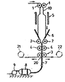
제1도는 본 발명에 관한 장치의 한실시예의 개략구성도.1 is a schematic structural diagram of an embodiment of an apparatus according to the present invention.
제2도는 그 주요부분 확대 사시도.2 is an enlarged perspective view of the main part thereof.
제3도는 제1도중 Ⅲ-Ⅲ선에 잇따른 화살표 단면도.3 is a cross-sectional view taken along the line III-III of FIG. 1.
제4도는 제1도중 Ⅳ-Ⅳ선에 잇따른 화살표 단면도.4 is a cross-sectional view taken along the line IV-IV in FIG.
제5a-b도는 본 발명에 관한 방법을 설명하는 도면.5a-b illustrate a method of the present invention.
* 도면의 주요부분에 대한 부호의 설명* Explanation of symbols for main parts of the drawings
1 : 제1핀치로울(Pinch roll) 2 : 제핀치 로울1: Pinch roll 1: 2 pinch roll
3 : 제핀치 로울 4 : 중간핀치로울3: zepinch roll 4: middle pinchroll
7 : 노즐 10 : 원단7: nozzle 10: fabric
10A, 10B, 10C, 10D : 대상편(帶狀片) 11 : 절단칼10A, 10B, 10C, 10D: Target piece 11: Cutting knife
12 : 홈 20 : 원단개구부12: groove 20: fabric opening
본 발명은 열가소성수지의 튜우브 형상원단을 튜우불러법에 따라 2축 연신하는 방법 및 그 장치에 관한 것으로 더욱 상세히 말하면, 튜우 형상 원단에 기체를 주입하는 방법 및 그 장치의 개량에 관한 것이다.The present invention relates to a method and a device for biaxially stretching a tubular fabric of a thermoplastic resin according to the tubular method, and more particularly, to a method for injecting gas into a tubular fabric and an improvement of the apparatus.
종래부터, 열가소성수지의 튜우브형상원단을 튜우불러법, 즉 튜우브형상원단을 각기 쌍을 이루는 제1핀치로울 및 제2핀치로울 사이에 삽통함과 동시에 기체를 봉입하여 가열 연신함에 따라 2축 연신시켜서 필름을 제조하는 것은 공지되어 있다.2. Description of the Related Art [0002] Conventionally, a tubular fabric of a thermoplastic resin is inserted into a tubular method, that is, a tube is inserted between a first pinch roll and a second pinch roller which make up a pair of tubular fabrics. It is known to draw and produce a film.
동 튜우브형상원단내에 기체를 주입하는 종래기술로서, 제2핀치로울으로부터 하류측에 출입할 수 있도록 설치된 회전불능의 1개의 고정커터로 튜우브형상원단을 선상으로 절단하고, 이렇게 절단한 부분을 넓혀서 노즐을 삽입하여 원단내에 공기를 주입하는 것(일본국 특공소 59-8341호 : 종래예 1)을 말한다.As a conventional technique of injecting gas into the tubular fabric, the tubular fabric is cut in a line with one non-rotating fixed cutter installed to enter the downstream side from the second pinch roller. It means widening and inserting a nozzle to inject air into the fabric (Japanese Patent Application No. 59-8341: Conventional Example 1).
또, 그밖의 종래 기술로서, 제1핀치로울, 제2핀치로울 및 1-10mm의 극간을 지닌 제3핀치로울 또는 둘레방향으로 다수의 홈을 지닌 제3핀치로울 사이에 튜우브형상원단을 삽통함과 동시에 튜우브형상원단의 단부로부터 기체를 주입하는 것(일본국 특공소 57-21450호 : 종래예 2)이 있다.In addition, as another conventional technique, a tubular fabric is inserted between a first pinch roll, a second pinch roll and a third pinch roll having a gap of 1-10 mm, or a third pinch roll having a plurality of grooves in the circumferential direction. At the same time, gas is injected from the end of the tubular fabric (Japanese Laid-Open Patent Application No. 57-21450: Conventional Example 2).
그런데, 전술한 종래기술중에서 종래예 1에 있어서는, 튜우브형상원단을 한개의 칼로 선상으로 절단하므로 두꺼운 원단을 반드시 충분히 절단할 수 없기 때문에 원단내에 기체를 반드시 확실하게 주입할 수 있다고는 할 수 없으며, 또 절단된 부분을 넓혀서 노즐을 삽입하지 않으면 아니되므로, 노즐을 원단안으로의 장착이 용이하지 않아서 작업하기 좋지 않아서, 장착할 수 있는 노즐의 사이즈에 제한이 있어서, 대형, 대구경화, 고속화된 튜우불러연신장치에는 부적합하다고 하는 문제점이 있었다.By the way, in the above-mentioned prior art, in the conventional example 1, since the tubular fabric is cut linearly with one knife, it cannot be said that gas can be certainly injected into the fabric because thick fabric cannot be cut sufficiently. In addition, the nozzle must be widened to insert the nozzle, so that the nozzle is not easy to mount into the fabric, and thus it is not easy to work, and there is a limit to the size of the nozzle that can be mounted. There was a problem that the stretching apparatus was unsuitable.
나아가서, 원단의 절단부분을 넓힘으로 해서 원단에 새로 연신방향으로의 파열이나, 주름이 발생하여 이러한 점으로 부터도 고정커터에 의한 원단의 원활한 절단을 할 수 없다고 하는 문제점이 있었다.Furthermore, there was a problem that the cutting part of the fabric was made wider, so that the fabric was ruptured in the stretching direction or wrinkled in the stretching direction, so that the fabric could not be cut smoothly by the fixed cutter.
또, 종래예 2에 있어서는, 이송되는 원단의 단부로부터 기체를 주입하기 때문에 소형설비로는 튜우브형상원단을 팽창시킬 수 있다고 하지만, 작업성이 낮고, 또 대형설비로는 원단의 팽창에 필요한 기체의 량을 충분히 주입할 수 없으므로, 작업하기 좋지 않을뿐 아니라, 실용화할 수 없다고 하는 문제점이 있었다.In addition, in the conventional example 2, since the gas is injected from the end of the fabric to be conveyed, the tubular fabric can be expanded with the small equipment, but the workability is low, and the gas required for the expansion of the fabric is large with the large equipment. Since it is impossible to inject a sufficient amount, there is a problem that not only it is not easy to work but also cannot be put into practical use.
여기에서, 본 발명의 목적은 튜우브형상원단내에 기체를 확실하게 주입할 수 있음과 동시에 주입할때의 작업성이 좋고, 적용할 수 있는 튜우브형상원단의 사이즈를 제한하지 않는 열가소성수지의 튜우불러연신방법 및 그 장치를 제공함에 있다.Here, the object of the present invention is to inject a gas into the tubular fabric reliably and at the same time have good workability when injecting the tubular of the thermoplastic resin which does not limit the size of the tubular fabric to be applied. The present invention provides a method and apparatus for stretching.
본 발명의 방법은, 열가소성수지의 튜우브형상원단을 각기 쌍을 이루는 제1핀치로울 및 제2핀치로울 사이에 삽통함과 동시에 기체를 봉입하여 가열연신하는 열가소성수지의 튜우불러연신장치에 있어서, 제2핀치로울의 하류측에서 튜우브형상원단을 원단이송방향으로 잇따라서 여러개의 대상편을 형성하도록 절단하고, 이러한 대상편중 1장의 대상편과 나머지 대상편을 분리하여 원단개구부를 형성한 다음, 동 원단개구부로부터 기체를 주입하여 일정한 부품음이 형성된 다음에 기체를 시일링하는 것을 특징으로 한다.In the method of the present invention, in the tubular stretching apparatus of a thermoplastic resin, the tubular fabric of the thermoplastic resin is inserted between each of the first pinch rolls and the second pinch rolls, which are paired with each other, and the gas is sealed and heated. On the downstream side of the second pinch roller, the tubular fabric is cut in succession to form the fabric piece, and one piece of the object piece and the other object piece are separated to form a fabric opening. Injecting gas from the distal end of the copper fabric is characterized by sealing the gas after a certain component sound is formed.
또, 본 발명의 장치는, 열가소성수지의 튜우브형상원단을 각기 쌍을 이루는 제1핀치로울 및 제2핀치로울 사이에 삽통함과 동시에 기체를 봉입하여 가열 연신하는 열가소성수지의 튜우불러연신장치에 있어서, 제2핀치로울의 하류측에, 여러개의 절단칼을 지닌 절단로울을 구비하여 제2핀치로울에서 이송되는 튜우부형상원단을 원단이송방향에 잇따라서 띠모양으로 절단하는 제3핀치로울과 튜우부형상원단내에 기체를 주입하는 노즐등을 배치하고, 동 노즐을 제3핀치로울에 따라 여러개의 대상편을 형성하도록 절단된 1장의 대상편과 나머지 대상편을 분리하여 형성된 원단개구부로부터 원단내에 전진후퇴할 수 있도록 설치하며, 제3핀치로울에는, 노즐삽통부가 형성된 것을 특징으로 한다.In addition, the apparatus of the present invention is inserted into a tubular stretching apparatus of a thermoplastic resin which inserts a tubular fabric of a thermoplastic resin between a pair of first pinch rollers and a second pinch roller, and simultaneously seals and heats a gas. In the downstream side of the second pinch roll, the third pinch roll for cutting the tub-shaped fabric conveyed from the second pinch roll in a strip shape in a direction of the fabric feed direction provided with a cutting roll having a plurality of cutting knives; A nozzle for injecting gas into the tubular shape fabric is placed, and the nozzle is separated from the fabric opening formed by separating one object piece and the other object piece cut to form a plurality of object pieces according to the third pinch roller. It is installed to retreat forward, and characterized in that the nozzle pinch portion is formed in the third pinch roll.
이에 따라, 본 발명은 제1핀치로울 및 제2핀치로울에 삽통된 튜우부형상원단을 제3핀치로울의 절단칼을 사용하여 띠모양으로 절단하고, 이렇게 띠모양으로 절단된 1장의 원단과 나머지 원단을 분리하여 원단개구부를 형성함과 동시에, 동원단개구부로부터 노즐을 원단내에 진입시켜서 원단내에 기체를 주입하므로써 원단이 팽창하여 일정한 크기의 부풀은 상태로 되어서 원단이 충분히 늘어나면, 노즐을 원단내에서 끌어냄에 따라 전술한 목적을 달성하려 한다.Accordingly, the present invention cuts the tubular fabric inserted into the first pinch roll and the second pinch roll into a strip shape using a cutting knife of the third pinch roll, and thus, the one piece of fabric and the rest cut into the strip shape. When the fabric is separated and the fabric opening is formed, the fabric is expanded by injecting gas into the fabric from the mobilization end opening, and the fabric expands and becomes a swelling state of a certain size. It is intended to achieve the aforementioned purpose by drawing from.
다음에 본 발명의 한 실시예를 도면에 따라서 설명한다. 먼저, 본 발명장치의 개략적인 구성을 나타낸 제1도에서, 각 한쌍의 제1핀치로울 및 제2핀치로울(2)이 상하방향으로 배치되었으며, 이것들 제1 및 제2핀치로울(1), (2)에는, 도면에 없는 압출기로부터 이송되는 튜우브형상의 원단(10)이 삽통되어 있다.Next, an embodiment of the present invention will be described with reference to the drawings. First, in FIG. 1 showing a schematic configuration of the apparatus of the present invention, each pair of first pinch rolls and second pinch rolls 2 are arranged in the vertical direction, and these first and second pinch rolls 1, In (2), the tubular
여기에서, 동원단(10)은 예컨대 폴리프로필렌, 폴리에틸렌, 에틸렌-초산비닐공중합체, 폴리염화비니리덴계수지등의 단층 또는 다층의 열가소성수지, 혹은 불포화카르복시산 또는 그 유도체에 의하여 변성된 열가소성수지를 사용한 다층의 재료로 되어 있다.Here, the
제1 및 제2핀치로울(1), (2) 사이에는 가열로(5) 및 대략 V자형으로 형성된 2장의 판으로 된 안정판(6)이 각기 배치되어 있다. 이때 제1핀치로울(1)은 원단(10)의 이송속도와 대략 동일한 주속으로 회전되고, 또 제2핀치로울(2)의 주속은 제1핀치로울 (1)에 비하여 빨라지도록 설정되어, 이에 따라 원단(10)이 가열로(5)에 의한 가열과 협동하여 원단이송방향(세로방향)으로 연신되도록 되어 있다.Between the first and
또, 원단(10)은, 공기의 봉입과 가열로(5)에 의한 가열에 따라서 팽창하고, 원단(10)의 부품은 상태로 되어서 가로방향으로 연신되도록 되어 있으며, 원단(10)은 2축방향으로 일정배율로 연신된 필름제품으로서 제조된다. 더욱이, 연신개시점에는 에어링(도면에 없음)으로 공기를 분무함에 따라 연신할때의 부풀어남의 안정을 도모할 수 있다.In addition, the
안정판(6)에 따라 부품은 형상으로 형성된 원단(10) (필름)이 점차로 편평하게 되도록 되어 있으며, 제2핀치로울(2)은, 서로 근접, 이반(離反)함에 따라 개폐되고, 또 안정판(6)은 제2핀치로울(2)와 연동하여 2장의 판이 서로 근접, 이반하여 상대거리를 조정할수 있도록 되어 있다.According to the
제2도에도 나타낸 바와 같이 제2핀치로울(2)의 하류측에는 제2핀치로울(2)와 같은 주속의 제3핀치로울(3)이 배치되어 있다. 제3핀치로울(3)은 제4도 나타낸 바와 같이, 착탈할 수 있는 2개의 절단칼(11) 및 이것들 절단칼(11)사이의 주면에 형성된 노즐삽통부를 형서하는 홈(12)을 지닌 고무제품의 절단로울(31)와, 2개의 절단칼 (11)을 각기 받는 2개소의 홈형상의 자인(紫刃)(13) 및 이것들 자인(13)사이의 주면에 형성되어 절단로울(31)의 홈(12)과 함께 노즐삽통부를 형성하는 홈(12)을 지닌 금속제의 받침로울(32)등으로 구성되었으며, 이것들 로울(31), (32)사이에 튜우브형상원단(10)를 삽통하면, 원단(10)을 원단이송방향에 잇따라서 띠모양으로 2장 겹친 상태에서 절단하도록 되어 있다.As shown in FIG. 2, the
여기에서, 원단(10)은 제1대상편(10A)과 제2-제4대상편(10B)(10C)(10 D)등으로 각기 절단되도록 되어 있으며, 제1대상편(10A)과 제3대상편이 단편으로서, 또 제2, 제4의 대상편(10B), (10D)의 2장 겹친상태에서 각기 분리할 수 있도록 되어 있다.Here, the
제3핀치로울(3)을 경과한 다음의 제1대상편(10A)은 제1도중 좌측의 드럼(21 )에 의하여 감겨지고, 한편 제2-제4대상편(10B)-(10D)은 제1도중 우측의 드럼 (22)에 의하여 감겨졌으며, 이에 따라 원단(10)은 제1대상편(10A)과 나머지 대상편 (10B)-(10D)이 분리되는 부분에 원단개구부(20)가 형성되도록 되어 있다.The
제3도에도 나타낸 바와 같이, 제2핀치로울(2) 및 제3핀치로울(3) 사이에는 제2핀치로울(2)에서 이송되는 원단(10)을 끌어잡아서 제3핀치로울(3)에 이송함과 동시에, 제2핀치로울(2)와 같은 주속도의 중간핀치로울(4)을 배치하고 있다. 중간핀치로울(4)은 중앙부에 압축부(15)를 각각 지닌 한쌍의 예컨대 고무제품의 로울으로 되어 있다. 원단(10)내에는 제3핀치로울(3)의 홈(12) 및 중간핀치로울(4)의 압축부(15)를 통과하여 막대형상의 노즐(7)이 진퇴할 수 있도록 되어 있다. 노즐(7)은 제1도에 나타낸 바와 같이, 압축가스를 대량으로 저장하는 탱크(8) 및 콤프레서(9)에 접속됨과 동시에 테이프(taper)형상으로 형성된 선단으로부터 원단(10)내에 진입하여 기체를 주입하도록 되어 있다.As also shown in FIG. 3, between the
다음에, 이와 같이 구성된 장치를 사용하여 열가소성수지의 원단(10)을 연신하는 방법에 대하여 제5도에 따라서 설명한다. 우선, 제5a도에 나타낸 바와 같이 도면에 없는 압출기로부터 이송된 편평튜우브형상의 원단(10)을 제1핀치로울(1), 제2핀치로울(2), 중간핀치로울(4) 및 제3핀치로울(3)의 순으로 삽통하여, 제3핀치로울(3)으로부터 이송된 원단(10)을 일정한 장력으로서 도면중 우측의 하나의 드럼(22)으로 감는다.Next, a method of stretching the
이러한 경우, 제3핀치로울(3)의 절단로울(31)에 미리 절단칼(11)을 장착하여 두어, 편평튜우브형상원단(10)을 제3핀치로울(3)으로 누르면서 2장 겹친상태에서 띠모양으로 절단한다. 그런다음, 제5b도에 나타낸 바와 같이, 2장을 겹친 띠모양의 원단(10)중의 1장, 즉 대상편(10A)을 일정한 장력으로서 다른 드럼(21)으로 감는다. 이에따라, 원단(10)이 제1대상편(10A)과 제2-제4대상편(10B)-(10D)으로 분리되어 제3핀치로울(3)의 근방에 원단개구부(20)가 형성된다.In this case, the cutting
나아가서, 제1핀치로울(2) 및 서로 격리하여 개방함과 동시, 안정판(6)을 제2핀치로울(2)에 연동시켜서 2장의 판사이를 넓힌 다음, 제5c도에 나타낸 바와 같이 원단개구부(20)로부터 원단(10)내에 제3핀치로울(3)의 홈(12) 및 중간핀치로울(4)의 압축부(15)를 통과하여 제2핀치로울(2)의 아래쪽 근방까지 노즐(7)을 진입시켜 탱크 (8) 및 콤프레서(9)에 의하여 노즐(7)의 선단으로부터 원단(10)내에 기체를 주입한다.Further, the
그런 다음, 가열로(5)로 가열된 원단(10)은, 기체의 주입과 함께 팽창하여 부풀음을 형성하여, 원단(10)이 가로방향으로 연신되고, 나아가서 제1핀치로울(1)와 제2핀치로울(2)의 주속차에 따라 원단(10)이 세로방향으로 연신된다. 원단(10)의 부풀은 지름이 일정한 크기로 되면, 제2핀치로울(2)을 서로 근접하여 폐쇄함과 함께 안정판 (6)을 제2핀치로울(2)와 연동시켜서 판사이의 거리를 짧게한 다음, 노즐(7)을 밀어내도록 하고, 다시금 절단로울(31)을 받침로울(32)에서 떨어지게 하여 절단칼 (11)을 제거한다.Then, the
그런 다음, 제5d도에 나타낸 바와 같이 제1핀치로울(1) 및 제2핀치로울(2) 사이의 튜우브형상원단(10)에 기체를 밀봉한 상태에서 원단(10)을 종횡방향, 결국 2축방향으로 연신시키면서 드럼(22)으로 필름을 감는다. 이와 같은 본 실시예에 의하면, 튜우브형상원단(10)을 2장의 절단칼(11)로 띠모양이 되게 절단하므로 두꺼운 원단이라도 충분히 절단할 수 있어서 원단(10)내에 기체를 확실하게 주입할 수 있을뿐 아니라 또한, 띠모양으로 절단하여 형성되는 제1대상편(10A)과 나머지 대상편(10B) - (10D)을 분리하여 형성된 원단개구부(10)로부터 노즐(7)을 원단(10)내에 진입시키고, 또 제3핀치로울(3)을 구성하는 각 로울(31), (32)에 홈(12)을 설치하였기 때문에, 노즐(7)의 원단(10)내로의 장착이 용이하게 되어서 작업성이 향상함과 동시에, 노즐 (7)의 사이즈가 한정되지 않는다.Then, as shown in FIG. 5D, the
노즐(7)의 사이즈가 한정되지 않음으로 하여, 튜우불러연신장치가 대형화, 고속화되어도 적용할 수 있다. 바꾸어 말하면, 본 실시예에 의하면 연신하는 튜우브형상원단(10)의 사이즈는 한정되지 않는다. 그뿐만 아니라 튜우브형상원단(10)을 전술한 종래예(1)와 같이 절단부분으로부터 넓히는 일이 없다는 사실 및 제3핀치로울(3)으로 누르면서 원단(10)을 절단하는 사실로부터, 원단(10)에 세로방향의 균열이나 주름이 발생하는 일이 없다. 따라서, 이러한 것에 기인하여 원단(10)의 절단이 충분히 할 수 없다거나, 절단칼의 파손을 방지할 수 있어 파손등에 따른 안전성을 감소하는 것을 회피할 수 있다. 또, 본 실시예에서는 제2, 3핀치로울(2), (3) 사이에 중간핀치로울(4)을 배치하였으므로 제2, 3핀치로울(2), (3)와 함께 원단(10)을 세로방향으로 충분히 연신력을 확보할 수 있다.Since the size of the
나아가서, 원단(10)내에 기체를 주입할 때, 제3핀치로울(3)뿐 아니라, 2장의 판으로 된 안정판(6)도 서로 근접, 격리할 수 있도록 하였으므로, 이것들을 각기 격리할 경우에는 기체가 원단(11)내에 주입하기 쉬워짐과 동시에 각기 근접할 경우에는 원단(필름)을 충분히 편평하게 한 상태에서 끌어당길 수 있다. 또, 절단칼(11)을 구비한 절단로울(31)와 쌍을 이루는 받침로울(32)에 홈형상의 자인(13)을 형성하였으므로, 튜우브형상원단(10)을 확실하게 절단할 수 있다.Furthermore, when injecting gas into the
나아가서, 노즐(7)의 선단을 테이퍼형상으로 형성하였으므로, 튜우브형상원단(10)내로의 노즐(7)의 진입이 원활하게 이루어져 이러한 점에서도 작업성을 향상시킬 수 있다.Further, since the tip of the
다음에 본 실시예의 효과를 확인하기 위하여 실험예 및 비교예에 대하여 설명한다.Next, an experimental example and a comparative example are demonstrated in order to confirm the effect of a present Example.
[실험예]Experimental Example
튜우브형상원단(10) : 상대점도 3.75(우베나일론 1024)의 폴리아미드(나일론)원료를 용융온도 250℃에서 압출기로부터 압출한 두께 120μm, 폭 500mm의 수냉원단 제1핀치로울과 제2핀치로울(2) 사이의 속도비(세로방향의 연신율) : 3 가로방향의 연신율 : 3Tube-shaped fabric (10): 120 μm thick, 500 mm wide water-cooled fabric with a polyamide (nylon) material having a relative viscosity of 3.75 (uben nylon 1024) extruded from an extruder at a melting temperature of 250 ° C., the first and second pinch rolls. (2) Speed ratio between (Elongation in the vertical direction): 3 Elongation in the horizontal direction: 3
이상의 조건하에서, 전술한 실시예의 방법에 따라서 공기를 주입하여 부풀음을 형성하고, 연신을 개시하여 튜우브형상원단(10)을 연신하였던 결과 튜우브형상원단 (10)의 흔들림도 없고, 1회의 조작에 따라서 폭 1500mm의 연신필름을 제조할 수 있었다.Under the above conditions, air was injected in accordance with the method of the above-described embodiment to form a swelling, and the stretching started and the
[비교예 1]Comparative Example 1
실험예와 마찬가지 원단(10)을 사용하여, 기체주입조작을 함에 있어, 종래예 1과 마찬가지로 고정커터로 튜우브형상원단(10)을 선상으로 절단하여 노즐을 장착하였다. 이때, 회전할 수 없는 고정커터로서 OLFA 커터(상품명)을 사용하였던바, 공기가 주입되기전, 즉 튜우브형상원단(10)이 가로방향(폭방향)으로 아직 연신하지 않은 상태에서는 커터로 원단(10)을 충분히 절단할 수 있으나, 원단(10)내에의 기체의 주입에 따라서 원단(10)의 폭을 넓히면, 연신도중의 원단(10)에 주름이 발생하기 쉬워져서, 주름섞임의 원단(10)에 따라 OLFA 커터의 칼이 접어져 버려서, 연속하여 기체를 원단(10)내에 주입할 수 없게 되었다.In the gas injection operation using the
이와 같은 연신조작을 여러번 반복하였으나 어느것도 원단(10)내에 기체를 충분히 주입할 수 없었다.This stretching operation was repeated several times, but none of them could sufficiently inject gas into the
[비교예 2]Comparative Example 2
실험예와 마찬가지의 원단을 사용하여 종래예(2)와 같이, 커터로 원단(10)을 절단하지 않고 원단(10)의 단부로부터 기체를 주입하였다. 이때, 이동하는 원단(10)의 단부로부터 노즐을 삽입하고, 원단(10)과 함께 이동하는 노즐으로부터 원단(10)내에 기체를 주입하였으나, 목적하는바 필름의 폭을 얻을 수 없었다. 구체적으로는, 연신하기전의 원단(10)의 폭을 실험예와 마찬가지로 500mm로 하였으나, 연신후의 필름폭은 1100mm을 한도로 가로방향의 연신율이 3배로 되는 1500mm에서는 여러번 연신조작을 하여서도 달성할 수 없었다.Using the same fabric as in Experimental Example, gas was injected from the end of the
더욱이, 전술한 실시예에서는, 제2 및 제3핀치로울(2), (3) 사이에 중간핀치로울(4)을 배치하기로 하였으나, 본 발명에서는 반드시 중간핀치로울(4)을 배치하는 것을 필요로 하지 않는다. 또, 제3핀치로울(3)에 설치된 절단칼(11)은 여러개이면 좋고 실험예와 같이 2장으로 한정되는 것은 아니다.Moreover, in the above-described embodiment, the intermediate pinch rolls 4 are arranged between the second and third pinch rolls 2 and 3, but in the present invention, it is necessary to arrange the intermediate pinch rolls 4 in the present invention. I don't need it. In addition, the cutting
또, 절단개소도 실시예에 한정하는 것은 아니다. 나아가서, 제3핀치로울(3)의 절단로울은 고무제품에 한정되는 것은 아니고, 또 받침로울(32)에 반드시 자인(13)을 형성하는 것을 필요로 하지 않는다. 또, 실시예에서는 노즐 삽통부를 홈(12)으로 하였으나, 본 발명의 노즐삽통부는, 예컨대 제3핀치로울(3)의 2장의 절단칼(11)사이의 일정위치에서 2개로 분할된 로울사이의 스페이스등, 제3핀치로울의 절단로울(31) 및 받침로울(32)을 폐쇄한 상태에서 노즐(7)을 원단(10)내에 삽입할 수 있는 구조라면 어떤 것이라도 좋다.In addition, a cutting point is not limited to an Example. Further, the cutting roller of the
또, 절단칼(11)의 둘레방향에는 적당한 커버를 설치하여 위험방지를 도모할 수도 있다. 전술한 바와같은 본 발명에 의하면, 튜우브형상원단내에 기체를 확실하게 주입할 수 있음과 동시에, 주입할때의 작업성이 좋고, 적용할 수 있는 튜우브형상원단의 사이즈가 제한되지 않는다고 하는 효과가 있다.In addition, an appropriate cover may be provided in the circumferential direction of the cutting
Claims (14)
Applications Claiming Priority (3)
| Application Number | Priority Date | Filing Date | Title |
|---|---|---|---|
| JP227786 | 1987-09-11 | ||
| JP62227786A JPS6471727A (en) | 1987-09-11 | 1987-09-11 | Method and device for tubular orientation of thermoplastic resin |
| JP62-227786 | 1987-09-11 |
Publications (2)
| Publication Number | Publication Date |
|---|---|
| KR890004849A KR890004849A (en) | 1989-05-10 |
| KR920002401B1 true KR920002401B1 (en) | 1992-03-23 |
Family
ID=16866362
Family Applications (1)
| Application Number | Title | Priority Date | Filing Date |
|---|---|---|---|
| KR1019880011502A KR920002401B1 (en) | 1987-09-11 | 1988-09-06 | Method of and apparatus for tubularly drawing thermoplastic resin |
Country Status (5)
| Country | Link |
|---|---|
| US (1) | US4869863A (en) |
| EP (1) | EP0306958B1 (en) |
| JP (1) | JPS6471727A (en) |
| KR (1) | KR920002401B1 (en) |
| DE (1) | DE3885982T2 (en) |
Families Citing this family (9)
| Publication number | Priority date | Publication date | Assignee | Title |
|---|---|---|---|---|
| US4983337A (en) * | 1987-11-12 | 1991-01-08 | Kohjin Co., Ltd. | Method and apparatus for producing stretched film |
| US5541011A (en) | 1991-10-28 | 1996-07-30 | Idemitsu Petrochemical Co., Ltd. | Oriented film easy to split |
| CA2077941C (en) * | 1992-07-07 | 2000-06-20 | John Louis Varadi | Automatic bubble blower for orientation film lines |
| CA2166680C (en) * | 1993-07-06 | 2002-03-05 | Kjell Sand | Apparatus for applying fibres during production of fibre reinforced products |
| US6395210B1 (en) | 1999-05-12 | 2002-05-28 | A&P Technology, Inc. | Pultrusion method and device for forming composites using pre-consolidated braids |
| NL1031597C2 (en) * | 2006-04-13 | 2007-10-16 | Fuji Seal Europe Bv | Device for manufacturing sleeve-shaped foil envelopes from a strip of sleeve-like foil material. |
| CN103203879B (en) * | 2013-04-17 | 2015-03-11 | 常熟市冠日新材料有限公司 | Method for preparing polyvinylidene fluoride film |
| CN107263559B (en) * | 2017-08-07 | 2018-11-23 | 胡海明 | A kind of waste plastic bottle regeneration system band device |
| CN107214740B (en) * | 2017-08-07 | 2018-10-16 | 胡海明 | A kind of waste plastic bottle regeneration selt-locking wrapping tape manufacture device |
Family Cites Families (13)
| Publication number | Priority date | Publication date | Assignee | Title |
|---|---|---|---|---|
| US2779973A (en) * | 1952-12-24 | 1957-02-05 | American Viscose Corp | Method and apparatus for forming continuous strips of sheet material from tubing |
| NL207418A (en) * | 1955-06-03 | 1900-01-01 | ||
| US3482280A (en) * | 1967-03-16 | 1969-12-09 | Cupples Container Co | Method and apparatus for producing polymeric sheet |
| US3661482A (en) * | 1968-08-28 | 1972-05-09 | Stuart L Brown Jr | Apparatus for manufacturing biaxially oriented film with dimensional stability |
| GB1282062A (en) * | 1969-03-08 | 1972-07-19 | Showa Denko Kk | A method and apparatus for manufacturing a biaxially oriented cylindrical film |
| JPS55100124A (en) * | 1979-01-27 | 1980-07-30 | Chisso Eng Kk | Startup of bi-axial stretching for plastic tube and its apparatus |
| JPS55150326A (en) * | 1979-05-14 | 1980-11-22 | Asahi Chem Ind Co Ltd | Automatic blow-up device for resin tube |
| JPS5658831A (en) * | 1979-10-19 | 1981-05-22 | Polymer Processing Res Inst | Biaxial stretching apparatus of tubular film |
| JPS57163532A (en) * | 1981-04-01 | 1982-10-07 | Polymer Processing Res Inst | Method for orienting film to traverse direction mainly |
| DE3119006C2 (en) * | 1981-05-13 | 1983-09-01 | Windmöller & Hölscher, 4540 Lengerich | Device for injecting air or gas into a tubular film web |
| JP3301087B2 (en) * | 1991-04-26 | 2002-07-15 | 松下電器産業株式会社 | Charging circuit |
| JPH05210155A (en) * | 1992-01-30 | 1993-08-20 | Canon Inc | Camera |
| JPH05216582A (en) * | 1992-02-04 | 1993-08-27 | Fujitsu Ltd | Command selection system |
-
1987
- 1987-09-11 JP JP62227786A patent/JPS6471727A/en active Granted
-
1988
- 1988-08-31 US US07/238,922 patent/US4869863A/en not_active Expired - Lifetime
- 1988-09-06 KR KR1019880011502A patent/KR920002401B1/en not_active IP Right Cessation
- 1988-09-08 DE DE88114704T patent/DE3885982T2/en not_active Expired - Fee Related
- 1988-09-08 EP EP88114704A patent/EP0306958B1/en not_active Expired - Lifetime
Also Published As
| Publication number | Publication date |
|---|---|
| KR890004849A (en) | 1989-05-10 |
| JPS6471727A (en) | 1989-03-16 |
| EP0306958A2 (en) | 1989-03-15 |
| JPH052498B2 (en) | 1993-01-12 |
| US4869863A (en) | 1989-09-26 |
| EP0306958A3 (en) | 1989-12-20 |
| EP0306958B1 (en) | 1993-12-01 |
| DE3885982T2 (en) | 1994-03-24 |
| DE3885982D1 (en) | 1994-01-13 |
Similar Documents
| Publication | Publication Date | Title |
|---|---|---|
| KR920002401B1 (en) | Method of and apparatus for tubularly drawing thermoplastic resin | |
| DE2245198C3 (en) | Bag making machine | |
| US3762250A (en) | Method of and apparatus for handling material | |
| US3283672A (en) | Bag | |
| US20220193973A1 (en) | Transporting a film tube, blown film line and method for producing a film | |
| US4434128A (en) | Method and apparatus for stretching thermoplastic polymer films | |
| US4490207A (en) | Transverse severing apparatus for webs | |
| KR910016570A (en) | Packing machine | |
| US3960062A (en) | Method of making a band of plastic bags | |
| DE1933667B2 (en) | MACHINE FOR THE INTERMITTING BLOW MANUFACTURING OF HOLLOW BODIES IN A DIVIDED HOLLOW FORM | |
| GB1162677A (en) | Process for making Isotropic Polymeric Film | |
| US5605502A (en) | Heat-shrinkable tubular film material | |
| US20160318638A1 (en) | Apparatus and Method of Using an Apparatus for Controlling a Film | |
| CN107161763B (en) | Material sheet position control device | |
| DE1504481C3 (en) | Method and device for the production of biaxially stretched flat films made of thermoplastic material | |
| EP3520989A1 (en) | Method and device for manufacturing a plastic film | |
| US7708921B2 (en) | Solution film-forming method | |
| US3695969A (en) | Plastics web slitting and sealing | |
| US4265616A (en) | Process for producing a heat-weakened strip in polyolefin film | |
| DE2602024A1 (en) | METHOD AND EQUIPMENT FOR MANUFACTURING LAMINATED THERMOPLASTIC FOAM SHEETS | |
| JP2012061843A (en) | Solution film forming method | |
| US20230100811A1 (en) | Device and method for deaerating a flattened tubular film | |
| AU619992B2 (en) | Improvements in or relating to heat-shrinkable tubular film material | |
| US20150053698A1 (en) | Cooling Film Wrapped Articles | |
| JPS637939B2 (en) |
Legal Events
| Date | Code | Title | Description |
|---|---|---|---|
| A201 | Request for examination | ||
| G160 | Decision to publish patent application | ||
| E701 | Decision to grant or registration of patent right | ||
| GRNT | Written decision to grant | ||
| FPAY | Annual fee payment |
Payment date: 20050309 Year of fee payment: 14 |
|
| LAPS | Lapse due to unpaid annual fee |