KR910009324B1 - 전환 어댑터 커넥터 조립체 - Google Patents
전환 어댑터 커넥터 조립체 Download PDFInfo
- Publication number
- KR910009324B1 KR910009324B1 KR1019850006884A KR850006884A KR910009324B1 KR 910009324 B1 KR910009324 B1 KR 910009324B1 KR 1019850006884 A KR1019850006884 A KR 1019850006884A KR 850006884 A KR850006884 A KR 850006884A KR 910009324 B1 KR910009324 B1 KR 910009324B1
- Authority
- KR
- South Korea
- Prior art keywords
- circuit board
- terminals
- header
- assembly
- connector assembly
- Prior art date
Links
Images


Classifications
-
- H—ELECTRICITY
- H01—ELECTRIC ELEMENTS
- H01R—ELECTRICALLY-CONDUCTIVE CONNECTIONS; STRUCTURAL ASSOCIATIONS OF A PLURALITY OF MUTUALLY-INSULATED ELECTRICAL CONNECTING ELEMENTS; COUPLING DEVICES; CURRENT COLLECTORS
- H01R12/00—Structural associations of a plurality of mutually-insulated electrical connecting elements, specially adapted for printed circuits, e.g. printed circuit boards [PCB], flat or ribbon cables, or like generally planar structures, e.g. terminal strips, terminal blocks; Coupling devices specially adapted for printed circuits, flat or ribbon cables, or like generally planar structures; Terminals specially adapted for contact with, or insertion into, printed circuits, flat or ribbon cables, or like generally planar structures
- H01R12/70—Coupling devices
- H01R12/77—Coupling devices for flexible printed circuits, flat or ribbon cables or like structures
- H01R12/78—Coupling devices for flexible printed circuits, flat or ribbon cables or like structures connecting to other flexible printed circuits, flat or ribbon cables or like structures
-
- H—ELECTRICITY
- H01—ELECTRIC ELEMENTS
- H01R—ELECTRICALLY-CONDUCTIVE CONNECTIONS; STRUCTURAL ASSOCIATIONS OF A PLURALITY OF MUTUALLY-INSULATED ELECTRICAL CONNECTING ELEMENTS; COUPLING DEVICES; CURRENT COLLECTORS
- H01R31/00—Coupling parts supported only by co-operation with counterpart
- H01R31/02—Intermediate parts for distributing energy to two or more circuits in parallel, e.g. splitter
-
- H—ELECTRICITY
- H01—ELECTRIC ELEMENTS
- H01R—ELECTRICALLY-CONDUCTIVE CONNECTIONS; STRUCTURAL ASSOCIATIONS OF A PLURALITY OF MUTUALLY-INSULATED ELECTRICAL CONNECTING ELEMENTS; COUPLING DEVICES; CURRENT COLLECTORS
- H01R12/00—Structural associations of a plurality of mutually-insulated electrical connecting elements, specially adapted for printed circuits, e.g. printed circuit boards [PCB], flat or ribbon cables, or like generally planar structures, e.g. terminal strips, terminal blocks; Coupling devices specially adapted for printed circuits, flat or ribbon cables, or like generally planar structures; Terminals specially adapted for contact with, or insertion into, printed circuits, flat or ribbon cables, or like generally planar structures
- H01R12/50—Fixed connections
- H01R12/59—Fixed connections for flexible printed circuits, flat or ribbon cables or like structures
- H01R12/61—Fixed connections for flexible printed circuits, flat or ribbon cables or like structures connecting to flexible printed circuits, flat or ribbon cables or like structures
-
- H—ELECTRICITY
- H01—ELECTRIC ELEMENTS
- H01R—ELECTRICALLY-CONDUCTIVE CONNECTIONS; STRUCTURAL ASSOCIATIONS OF A PLURALITY OF MUTUALLY-INSULATED ELECTRICAL CONNECTING ELEMENTS; COUPLING DEVICES; CURRENT COLLECTORS
- H01R12/00—Structural associations of a plurality of mutually-insulated electrical connecting elements, specially adapted for printed circuits, e.g. printed circuit boards [PCB], flat or ribbon cables, or like generally planar structures, e.g. terminal strips, terminal blocks; Coupling devices specially adapted for printed circuits, flat or ribbon cables, or like generally planar structures; Terminals specially adapted for contact with, or insertion into, printed circuits, flat or ribbon cables, or like generally planar structures
- H01R12/70—Coupling devices
- H01R12/71—Coupling devices for rigid printing circuits or like structures
- H01R12/712—Coupling devices for rigid printing circuits or like structures co-operating with the surface of the printed circuit or with a coupling device exclusively provided on the surface of the printed circuit
-
- H—ELECTRICITY
- H01—ELECTRIC ELEMENTS
- H01R—ELECTRICALLY-CONDUCTIVE CONNECTIONS; STRUCTURAL ASSOCIATIONS OF A PLURALITY OF MUTUALLY-INSULATED ELECTRICAL CONNECTING ELEMENTS; COUPLING DEVICES; CURRENT COLLECTORS
- H01R12/00—Structural associations of a plurality of mutually-insulated electrical connecting elements, specially adapted for printed circuits, e.g. printed circuit boards [PCB], flat or ribbon cables, or like generally planar structures, e.g. terminal strips, terminal blocks; Coupling devices specially adapted for printed circuits, flat or ribbon cables, or like generally planar structures; Terminals specially adapted for contact with, or insertion into, printed circuits, flat or ribbon cables, or like generally planar structures
- H01R12/70—Coupling devices
- H01R12/77—Coupling devices for flexible printed circuits, flat or ribbon cables or like structures
- H01R12/79—Coupling devices for flexible printed circuits, flat or ribbon cables or like structures connecting to rigid printed circuits or like structures
-
- H—ELECTRICITY
- H01—ELECTRIC ELEMENTS
- H01R—ELECTRICALLY-CONDUCTIVE CONNECTIONS; STRUCTURAL ASSOCIATIONS OF A PLURALITY OF MUTUALLY-INSULATED ELECTRICAL CONNECTING ELEMENTS; COUPLING DEVICES; CURRENT COLLECTORS
- H01R13/00—Details of coupling devices of the kinds covered by groups H01R12/70 or H01R24/00 - H01R33/00
- H01R13/62—Means for facilitating engagement or disengagement of coupling parts or for holding them in engagement
- H01R13/621—Bolt, set screw or screw clamp
Landscapes
- Coupling Device And Connection With Printed Circuit (AREA)
- Details Of Connecting Devices For Male And Female Coupling (AREA)
- Arrangements For Transmission Of Measured Signals (AREA)
Abstract
내용 없음.
Description
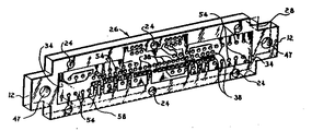
제1도는 0.125인치×0.250인치 간격으로부터 0.100인치×0.100인치간격으로 전환하는 어댑터 커넥터조립체의 분해 사시도.
제2도는 커넥터 조립체와 그에 결합하는 전형적인 리본 케이블커넥터의 사시도.
제3도는 전환 어댑터 커넥터 조립체에 부착되는 리본 케이블 커넥터의 사시도.
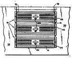
제4도는 굴곡 단자의 삽입을 위한 구멍이 있는 회로판의 제1측면의 확대도.
제5도는 제4도에 도시된 것과 다른 배열의 접지선이 있는 회로판의 확대도.
제6도는 종래 기술의 회로판 커넥터 조립체의 사시도.
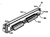
제7도는 초소형의 D형 헤더가 있는 다른예의 커넥터 조립체의 사시도.
제8도는 볼트로 패널상에 장착된 커넥터 조립체의 정면도.
제9도는 패널상에 미끄러질 수 있게 장착된 커넥터 조립체의 정면도이다.
* 도면의 주요부분에 대한 부호의 설명
12 : 회로판 14 : 유전체 하우징
16 : 신속 제거 헤더 18 : 덮개
20 : 장착 클립 22 : 단자 수용 채널
26 : 회로판의 제2측면 28 : 회로판의 제1측면
30 : 사각형 핀(단자) 32 : 굴곡 단자
40 : 걸쇠
본 발명은 서로 다른 전기 장치들 사이의 입출력 인터페이스용 전기 커넥터에 관한 것으로, 더 구체적으로는, 서로 다른 전기 장치들 사이를 상호연결하도록 회로판을 이용하는 전환 입출력 어댑터 커넥터(transition input/output adapter connector)조립체에 관한 것이다.
미국 특허 제4,331,370호는 집적된 다층 인쇄 회로판에 입출력 통로를 제공하는 장치를 기술하고 있다. 도금된 관통 구멍이 있는 커넥터용의 한쌍의 카드와 절연물질로 이루어진 한쌍의 모듈이 인쇄 회로판내에 입출력 신호 경로를 제공한다. 이러한 한쌍의 모듈과 카드의 필요성은 오늘날의 소형화 추세에 비추어 전자장치가 너무 커지게 한다.
미국 특허 제4,440,463호는 금속화되어 있는 플라스틱제 접지 삽입체(인서어트)를 가진 전기 커넥터를 기술하고 있다. 이러한 형태의 커넥터는 외부 쉘 커넥터(shell connector)에 연결된 접점들중 적어도 몇 개의 접점의 전극 부분을 전기적으로 접지시키는 수단을 제공한다. 이 수단은 비록 접지 방법으로서는 가치가 있을지라도 어떤 간격의 전자 장치로부터 다른 간격의 장치로 전환하는 데에는 사용될 수 없다.
본 발명은 IBM 360 및 370 컴퓨터, 플러그 겸용주 프레임, 및 관련 주변 장치의 입출력 인터페이스를 제공하는 커넥터 조립체에 관한 것이다.
또한, 이 조립체는 대개 0.100인치(2.54mm)×0.100인치(2.54mm)의 중심 격자 간격의 암(female) 커넥터를 끝에 가지는 고속, 고성능 케이블 장치를 위한 인터페이스를 제공한다. 본 발명은 0.125인치(3.175mm)×0.250인치(6.35mm)중심간격의 IBM 입출력 장치로부터 어떤 소망의 격자 크기, 예를 들어, 0.100×0.100인치의 표준 격자 또는 군용 D-형 초소형으로 사용되는 것과 같은 다른 표준 격자들로의 격자 크기 전환장치를 제공한다. 이러한 커넥터는 유사한 기능을 갖는 다른 형태의 장치보다 적은 수의 케이블과 커넥터를 사용하고, 이러한 커넥터는 신호 경로에서의 변화부와 단락부가 적으며 융통성이 높다.
이러한 커넥터는 0.125인치×0.250인치의 중심 간격의 격자로부터 표준 격자로 전환하는 격자 장치를 제공하도록 관통 구멍이 있는 인쇄회로판을 이용한다. 이것은 회로판의 신호 경로를 전환 기구로 사용함으로써 달성된다. 간격의 수와 크기는 사용자가 원하는 바대로 변경될 수 있고 적절한 접지 장치가 삽입될 수 있다. 대표적인 예의 이 조립체는 한쪽 측면에 굴곡(서펜트)단자를 이용하고, 다른 측면에는 회로판을 통과하는 사가형 핀을 이용한다. 굴곡 단자들은 열가소성 물질의 하우징내에 수용되고, 이 하우징은 금속제 장착 클립에 의해 회로판의 한쪽 측면에 고정된다. 회로판의 다른 측면에는, 2×25개 위치들을 가진 헤더(header)가 핀들에 끼워져 결합되고, 덮개가 헤더 둘레에 설치되어 간결한 조립체를 형성한다.
제1도에 도시된 입축력 어댑터 커넥터 조립체는 여러 부분들로 이루어져 있다. 그 한 부분은 단자들이 끼워지는 여러개의 관통 구멍들을 가진 회로판(12)이다. 그 단자는 각 측면상에서 어떠한 형태의 전기 접속부도 가질 수 있다.
그러나, 제1도에 있어서는 , 그러한 단자들로서, 사각형핀(30)이 회로판(12)의 제2측면(26)에 도시되어 있고, 굴곡 단자들(32)이 회로판(12)의 제1측면(28)에 도시되어 있다. 회로판(12)의 전방부, 즉, 제2측면(26)은 신속 제거 헤더(header)(16)를 장착하기에 적합하게 되어있다. 회로판(12)의 후방부, 즉, 제1측면(28)은 굴곡 단자(32)를 수용하는 크기의 단자 수용 채널(22)를 가지고 있는 유전체 하우징(14)에 장착된다.
장착 클립(20)은 회로판(12)을 유전체 하우징(14)에 고정시키는데 사용된다. 그 장착 클립(20)은 회로판(12)으로부터 유전체 하우징(14)과 장착 패널(70)(제8도)로의 전기적 접지를 제공한다. 신속 제거 헤더(16)는 여러개의 관통 구멍(도시 안됨)을 가지고 있는데, 신속 제거 헤더(16)가 회로판(12)에 결합될 때 회로판의 사각형핀들(30)이 그 관통 구멍들을 통과한다. 덮개(18)가 회로판(12)의 제2측면(26)을 둘러싸고, 후술되는 바와 같이 볼트들로 고정됨으로써 신속 제거 헤더(16)를 제 위치에 유지한다. 신속 제거 헤더(16)상의 겉쇠(40)는 케이블(46)에의 표준 접속부를 가진 리본 케이블 커넥터(42)(제2도)상의 겉쇠 노치(44)와 결합한다. 리본 케이블 커넥터(42)의 소켓 단자들이 회로판(12)의 사각형핀(30)들과 결합한다. 리본 케이블 커넥터(42)상의 분극 탭(polarizing tab)(50)이 신속 제거 헤더(16)내에 있는 분극 슬로트(52)와 결합한다.
구멍(47)을 통과하는 핀 또는 볼트(48)가 장착 클립(20), 회로판(12) 및 유전체 하우징(14)을 서로 함께 고정시키는데 사용될 수 있다. 유전체 하우징(14), 회로판(12) 및 덮개(18)에 있는 구멍들(24)은 전체 조립체를 고정시키기 위한 나사 또는 볼트를 수용한다.
회로판(12)상의 회로 영역(34)은 제4도 및 5도에 도시된 바와 같이 여러 가지로 구성될 수 있다. 즉, 임의의 수의 위치들이 채택될 수 있고, 임의의 수의 접지 종단부(termination)들이 제공될 수 있다. 또한, 간격과 전기적 배열도 변경될 수 있다. 제4 및 5도를 참조하면, 회로판(12)의 제1측면(28)은 굴곡 단자(32)를 수용하는 구멍들(54)을 가지고 있고, 구멍(38)은 제2측면(26)으로부터 그 구멍내로 삽입되고 증기상 공정(vaporphase process)에 의해 그 구멍에 납땜되는 사각형 핀들(30)의 단부들을 수용한다. 굴곡 단자(32)의 단부(33)는 삽입된 후 동일한 증기상 공정에 의해 납땜되며 제2측면(26)상에서 볼 수 있다. 도선(58)은 전형적인 접지선을 나타내고, 도선(56)은 격자 형태의 전형적인 신호선을 나타낸다.
제6도에 도시된 종래의 장치(60)는 하우징(68)으로부터 튀어나온 회로판(62)과 그 회로판에 부착된 직각 헤더(64)를 필요로 하므로 매우 복잡하고 크다.
본 발명에서 사용되는 다른 예의 하우징(14A)은 제7도에 도시된 바와 같이 신속 제거 헤더(16)대신에 초소형의 D-형 헤더(16A)를 갖고 있다. 이 실시예에서의 덮개(18A)와 회로판(12A)과 하우징(14A)은 제1 및 2도에 도시된 것과 같은 방식으로 작용한다. 이러한 구성은 MIL-C-24308와 같은 미국 표준 군사규격에 일치한다.
제8 및 9도는 컴퓨터에서 볼 수 있는 것과 같은 패널(70)에 본 발명의 어댑터 커넥터 조립체(10)를 장착시키는 다른 방법들을 보여준다. 제8도에 있어서, 이 어댑터 커넥터 조립체(10)는 구멍(24)을 통해 적절한 위치에서 나사로 고정되고 장착 클립(20)과 볼트(48)로 패널(70)에 접지된다. 유전체 하우징(14)은 단자 수용 채널(22)을 통하여 그와 짝을 이루는 커넥터의 단자를 수용한다. 제9도에서, 어댑터 커넥터 조립체(10)는 볼트로 조여지는 대신 홈(72)에 끼워져 패널(70)에 설치된다.
전술한 본 발명의 어댑터 커넥터 조립체는 어떤 밀접하게 집적된 장치를 위한 입출력 신호 경로들의 수를 변화시키거나 증가시키는 수단을 제공함과 동시에, 그 조립체에서 최소한의 부품을 사용하여 제1크기의 간격으로부터 제2크기의 간격으로의 전환을 가능케 한다.
Claims (5)
- (a) 다수의 관통 구멍과 제1 및 제2측면(28,26)을 가지며 적어도 한쪽 측면상에 신호선(56)이 있고 각 관통 구멍에는 전기 단자들(32,30)이 그들의 일 접촉 단부에서 그 구멍과 전기적으로 접촉하여 장착되어 있으며 적어도 몇몇 단자들(32)은 그들의 반대측 접촉 단부에서 제1측면(28)으로부터 돌출하고 그 나머지 단자들(30)은 그들의 반대측 접촉 단부에서 제2측면(26)으로부터 돌출하여 있는 회로판(12), (b) 상기 회로판의 제1측면(28)상의 단자들(32)과 결합하는 다수의 단자 수용 채널(22)이 있는 유전체 하우징(14), (c) 상기 회로판의 제2측면(26)상의 단자들(30)과 결합하는 다수의 단자 수용 채널이 있는 헤더(16), 및 (d) 상기 회로판, 하우징 및 헤더를 서로 함께 보유하는 수단(20,18)으로 구성되고, 컴퓨터 장치, 플러그 겸용 주 프레임 및 관련주변 장치와의 입출력 인터페이스로 사용되는 전환 어뎁터 커넥터 조립체(10)로서, 상기 회로판(12)의 제1측면(28)으로부터 돌출하는 상기 단자들(32)이 굴곡 단자들이고, 상기 헤더(16)는 상기 회로판의 제2측면(26)으로부터 돌출하는 단자들(30)에 끼워질 수 있는 신속 제거 헤더이며, 상기 단자들(30)이 직선 핀들인 것을 특징으로 하는 전환 어댑터 커넥터 조립체.
- 제1항에 있어서, 이 조립체(10)가 컴퓨터 패널(70)상에 장착되고, 리본 케이블 커넥터(42)가 회로판(12)의 제2측면(26)상의 핀단자들(30)과 결합되는 전환 어댑터 커넥터 조립체.
- 제2항에 있어서, 상기 헤더(16)가 리본 케이블 커넥터(42)상에 있는 걸쇠 노치(44)와 결합하는 걸쇠(40)를 가지는 전환 어댑터 커넥터 조립체.
- 제1항에 있어서, 상기 헤더가 초소형의 D-형 헤더(16A)인 전환 어댑터 커넥터 조립체.
- 제1항에 있어서, 회로판, 하우징 및 헤더를 함께 보유하는 상기 수단은 상기 회로판(12)과 유전체 하우징(14)을 보유하는 클립(20)과, 상기 회로판 및 유전체 하우징이 상응하는 구멍들(24)과 정렬되고 나사 또는 볼트가 결합되는 구멍들(24)을 가지고 상기 헤더(16)를 둘러싸고 덮개(18)인 전환 어댑터 커넥터 조립체.
Applications Claiming Priority (3)
| Application Number | Priority Date | Filing Date | Title |
|---|---|---|---|
| US653381 | 1984-09-21 | ||
| US653,381 | 1984-09-21 | ||
| US06/653,381 US4585284A (en) | 1984-09-21 | 1984-09-21 | Transition adapter connector employing a printed circuit board |
Publications (2)
| Publication Number | Publication Date |
|---|---|
| KR860002883A KR860002883A (ko) | 1986-04-30 |
| KR910009324B1 true KR910009324B1 (ko) | 1991-11-09 |
Family
ID=24620627
Family Applications (1)
| Application Number | Title | Priority Date | Filing Date |
|---|---|---|---|
| KR1019850006884A KR910009324B1 (ko) | 1984-09-21 | 1985-09-20 | 전환 어댑터 커넥터 조립체 |
Country Status (10)
| Country | Link |
|---|---|
| US (1) | US4585284A (ko) |
| EP (1) | EP0175426B1 (ko) |
| JP (1) | JPS6178079A (ko) |
| KR (1) | KR910009324B1 (ko) |
| AT (1) | ATE54514T1 (ko) |
| AU (1) | AU573508B2 (ko) |
| BR (1) | BR8504546A (ko) |
| CA (1) | CA1220255A (ko) |
| DE (1) | DE3578626D1 (ko) |
| MX (1) | MX157994A (ko) |
Families Citing this family (23)
| Publication number | Priority date | Publication date | Assignee | Title |
|---|---|---|---|---|
| US4881902A (en) * | 1984-09-21 | 1989-11-21 | E. I. Du Pont De Nemours And Company | Electrical terminator device |
| JPS61180510A (ja) * | 1985-02-05 | 1986-08-13 | 矢崎総業株式会社 | 合体構造型電気接続箱 |
| JPS61248380A (ja) * | 1985-04-24 | 1986-11-05 | ヒロセ電機株式会社 | 多心フラツトケ−ブルの圧接結線方法及び多心フラツトケ−ブル用電気コネクタ |
| EP0614248B1 (en) * | 1986-06-13 | 1996-11-20 | The Whitaker Corporation | Local area network interface |
| US4725249A (en) * | 1986-09-22 | 1988-02-16 | American Telephone & Telegraph Company | Connector assembly |
| US4767357A (en) * | 1987-06-10 | 1988-08-30 | E. I. Du Pont De Nemours And Company | Daisy chain connector |
| US4832619A (en) * | 1988-08-05 | 1989-05-23 | E. I. Du Pont De Nemours And Company | Pin mounted support system for printed circuit cards and connectors |
| DE3934288A1 (de) * | 1989-10-13 | 1991-04-18 | Hans Moll | Verbindungssystem, insbesondere fuer rechnernetzwerke |
| US5149274A (en) * | 1991-04-01 | 1992-09-22 | Amphenol Corporation | Electrical connector with combined circuits |
| JP2500272Y2 (ja) * | 1991-10-30 | 1996-06-05 | 不二電機工業株式会社 | コネクタ |
| EP0651920A4 (en) * | 1992-07-24 | 1997-05-14 | Berg Tech Inc | APPARATUS FOR CONNECTING COMPUTER DEVICES. |
| EP0746883A1 (en) * | 1993-08-17 | 1996-12-11 | Berg Electronics Manufacturing B.V. | Self-switching connector for electronic systems |
| US5409387A (en) * | 1993-08-17 | 1995-04-25 | Berg Technology, Inc. | Connector with passive switch for electrostatic discharge |
| TW254004B (en) * | 1993-12-07 | 1995-08-11 | Methode Electronics Inc | Low profile electrical adaptor |
| US5895297A (en) * | 1997-02-26 | 1999-04-20 | Lucent Technologies, Inc. | Cable interconnection assembly |
| US6146153A (en) * | 1999-03-09 | 2000-11-14 | 3Com Corporation | Adapter apparatus and method for transmitting electronic data |
| US6250956B1 (en) * | 1999-11-09 | 2001-06-26 | Pulizzi Engineering Inc. | Electrical equipment and method of assembling same |
| US6183269B1 (en) | 2000-01-27 | 2001-02-06 | Itt Manufacturing Enterprises, Inc. | Termination adaptor for PCB |
| JP2009158136A (ja) * | 2007-12-25 | 2009-07-16 | Yamaichi Electronics Co Ltd | レセプタクル部材、および、それが用いられる記録媒体接続用コネクタ |
| US7758353B2 (en) * | 2008-03-14 | 2010-07-20 | Motorola, Inc. | Circuit board connector assembly and method for assembling such an assembly |
| KR200461021Y1 (ko) * | 2010-10-28 | 2012-06-15 | 주식회사 제이앤티씨 | 전자기기의 케이블용 커넥터 플러그 |
| US8657630B1 (en) * | 2011-05-10 | 2014-02-25 | Bae Systems Information And Electronic Systems Integration Inc. | Dual connector plate |
| JP6834855B2 (ja) * | 2017-09-01 | 2021-02-24 | トヨタ自動車株式会社 | 車両下部構造 |
Family Cites Families (15)
| Publication number | Priority date | Publication date | Assignee | Title |
|---|---|---|---|---|
| US3551874A (en) * | 1968-07-31 | 1970-12-29 | Amp Inc | Multiple coaxial connector |
| US4012094A (en) * | 1974-06-13 | 1977-03-15 | Rca Corporation | Electron tube socket having spring-wire contacts |
| US4072402A (en) * | 1976-01-19 | 1978-02-07 | Butler Robert J | Electrical connector |
| US4080028A (en) * | 1976-12-09 | 1978-03-21 | Powell Electrical Manufacturing Company | Printed circuit board connector adapter |
| US4105275A (en) * | 1977-08-18 | 1978-08-08 | E. I. Du Pont De Nemours And Company | Header with integral latch members |
| US4272145A (en) * | 1979-10-22 | 1981-06-09 | Ford Motor Company | Connector lock release |
| US4331370A (en) * | 1980-04-28 | 1982-05-25 | Amp Incorporated | Connection system for printed circuit boards |
| US4389021A (en) * | 1981-03-16 | 1983-06-21 | Amp Incorporated | Panel mounted connector for use in confined areas |
| SE8104572L (sv) * | 1981-07-28 | 1983-01-29 | Englund Thomas U Y | Uppberningsanordning |
| US4440463A (en) * | 1981-10-26 | 1984-04-03 | The Bendix Corporation | Electrical connector having a metallized plastic grounding insert |
| US4433886A (en) * | 1981-12-17 | 1984-02-28 | Elco Corporation | Connector mounting for integrated circuit chip packages |
| EP0105351A1 (en) * | 1982-04-05 | 1984-04-18 | Akzona Incorporated | Interface connector |
| GB2130818A (en) * | 1982-10-19 | 1984-06-06 | Mcmurdo Instr Co Ltd The | Electrical connecting arrangement |
| US4506937A (en) * | 1983-05-02 | 1985-03-26 | Amp Incorporated | Latching-grounding blocks |
| AU4867785A (en) * | 1985-10-25 | 1987-05-19 | Anico Marketing Inc. | Connector interface |
-
1984
- 1984-09-21 US US06/653,381 patent/US4585284A/en not_active Expired - Lifetime
-
1985
- 1985-09-18 BR BR8504546A patent/BR8504546A/pt not_active IP Right Cessation
- 1985-09-19 CA CA000491167A patent/CA1220255A/en not_active Expired
- 1985-09-20 AT AT85201516T patent/ATE54514T1/de not_active IP Right Cessation
- 1985-09-20 DE DE8585201516T patent/DE3578626D1/de not_active Expired - Lifetime
- 1985-09-20 KR KR1019850006884A patent/KR910009324B1/ko not_active IP Right Cessation
- 1985-09-20 AU AU47644/85A patent/AU573508B2/en not_active Ceased
- 1985-09-20 EP EP85201516A patent/EP0175426B1/en not_active Expired - Lifetime
- 1985-09-20 JP JP60206770A patent/JPS6178079A/ja active Granted
- 1985-10-01 MX MX1A patent/MX157994A/es unknown
Also Published As
| Publication number | Publication date |
|---|---|
| AU573508B2 (en) | 1988-06-09 |
| JPH0332187B2 (ko) | 1991-05-10 |
| KR860002883A (ko) | 1986-04-30 |
| AU4764485A (en) | 1986-03-27 |
| JPS6178079A (ja) | 1986-04-21 |
| ATE54514T1 (de) | 1990-07-15 |
| EP0175426A2 (en) | 1986-03-26 |
| MX157994A (es) | 1988-12-29 |
| BR8504546A (pt) | 1986-07-15 |
| EP0175426B1 (en) | 1990-07-11 |
| EP0175426A3 (en) | 1987-01-28 |
| US4585284A (en) | 1986-04-29 |
| CA1220255A (en) | 1987-04-07 |
| DE3578626D1 (de) | 1990-08-16 |
Similar Documents
| Publication | Publication Date | Title |
|---|---|---|
| KR910009324B1 (ko) | 전환 어댑터 커넥터 조립체 | |
| EP0405454B1 (en) | Coaxial contact element | |
| US5228864A (en) | Connectors with ground structure | |
| KR960002138B1 (ko) | 모듈형 전기 커넥터 | |
| EP0460975B1 (en) | Connectors with ground structure | |
| US7497738B2 (en) | Electrical connector interacting between two different interfaces | |
| US5479320A (en) | Board-to-board connector including an insulative spacer having a conducting surface and U-shaped contacts | |
| KR940011265B1 (ko) | 접지 구조물을 갖고 있는 커넥터 | |
| EP0002890B1 (en) | Shielded electrical connector | |
| US6319066B2 (en) | Compact electrical adapter for mounting to a panel connector of a computer | |
| EP1516400A1 (en) | Electrical connector with wire management module | |
| US5415566A (en) | Shielded electrical connector assembly | |
| US6296518B1 (en) | Stacked electrical connector assembly | |
| CA2273114A1 (en) | Multi-pin connector for flat cable | |
| US5151036A (en) | Connectors with ground structure | |
| US5141453A (en) | Connectors with ground structure | |
| US5281155A (en) | Electrical connector with electrostatic discharge protection | |
| US5261829A (en) | Connectors with ground structure | |
| US20050130490A1 (en) | High speed cable assembly including finger grips | |
| CA2291355C (en) | Printed circuit for modular plug | |
| US4993971A (en) | EMI resistant electrical connector | |
| EP0643448B1 (en) | Coaxial connector for connection to a printed circuit board | |
| JPH02177278A (ja) | 電気接続装置およびヘッダー | |
| KR100790762B1 (ko) | 케이블 커넥터 및 그 조립용 키트 | |
| US5261828A (en) | Misalignment tolerant edge connector assembly |
Legal Events
| Date | Code | Title | Description |
|---|---|---|---|
| A201 | Request for examination | ||
| E601 | Decision to refuse application | ||
| E902 | Notification of reason for refusal | ||
| J2X1 | Appeal (before the patent court) |
Free format text: APPEAL AGAINST DECISION TO DECLINE REFUSAL |
|
| E902 | Notification of reason for refusal | ||
| G160 | Decision to publish patent application | ||
| E701 | Decision to grant or registration of patent right | ||
| GRNT | Written decision to grant | ||
| FPAY | Annual fee payment |
Payment date: 19941103 Year of fee payment: 4 |
|
| LAPS | Lapse due to unpaid annual fee |