KR910008907B1 - Working apparatus for use in an assembling processing line - Google Patents
Working apparatus for use in an assembling processing line Download PDFInfo
- Publication number
- KR910008907B1 KR910008907B1 KR1019870015244A KR870015244A KR910008907B1 KR 910008907 B1 KR910008907 B1 KR 910008907B1 KR 1019870015244 A KR1019870015244 A KR 1019870015244A KR 870015244 A KR870015244 A KR 870015244A KR 910008907 B1 KR910008907 B1 KR 910008907B1
- Authority
- KR
- South Korea
- Prior art keywords
- work
- head member
- work head
- pallet
- movable
- Prior art date
Links
Images


Classifications
-
- B—PERFORMING OPERATIONS; TRANSPORTING
- B23—MACHINE TOOLS; METAL-WORKING NOT OTHERWISE PROVIDED FOR
- B23P—METAL-WORKING NOT OTHERWISE PROVIDED FOR; COMBINED OPERATIONS; UNIVERSAL MACHINE TOOLS
- B23P21/00—Machines for assembling a multiplicity of different parts to compose units, with or without preceding or subsequent working of such parts, e.g. with programme control
Landscapes
- Engineering & Computer Science (AREA)
- Mechanical Engineering (AREA)
- Automatic Assembly (AREA)
- Multi-Process Working Machines And Systems (AREA)
- Automobile Manufacture Line, Endless Track Vehicle, Trailer (AREA)
Abstract
내용 없음.No content.
Description
도면은 본 발명의 실시예를 도시한 것으로서,The drawings show an embodiment of the present invention.
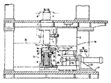
제1도는 가공 또는 조립라인의 작업장치의 전체구성도.1 is the overall configuration of the working device of the processing or assembly line.
제2도는 작업구동수단의 단면도.2 is a cross-sectional view of the work driving means.
제3도는 작업헤드부재의 단면도.3 is a cross-sectional view of the working head member.
제4도는 록너트와 코오킹부재와의 관계를 도시한 설명도.4 is an explanatory diagram showing the relationship between the lock nut and the caulking member.
제5도는 작업헤드부재를 생략하여 도시한 상기 작업장치의 평면도.5 is a plan view of the work device with the work head member omitted.
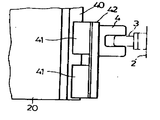
제6도는 작업헤드부재가 선회아암에 장착된 상태의 설명도.6 is an explanatory view of a state in which the work head member is mounted on the swing arm.
제7도는 승강부재의 걸어맞춤핀과 작업헤드부재의 피걸어맞춤부와의 걸어맞춤관계를 도시한 도면.FIG. 7 is a diagram showing the engagement relationship between the engagement pin of the elevating member and the engaged portion of the work head member.
* 도면의 주요부분에 대한 부호의 설명* Explanation of symbols for main parts of the drawings
A : 리어액슬(가공물) B : 팔레트A: Rear axle (workpiece) B: Pallet
C : 콘베이어수단 D : 록너트C: Conveyor means D: Lock nut
1 : 작업헤드부재 2 : 승강부재1: work head member 2: lifting member
5,26 : 실린더 24 : 작업구동수단5,26 cylinder 24: work drive means
50 : 상승구동수단50: ascent drive means
본 발명은, 가공 또는 조립라인의 작업장치에 관한 것이다.The present invention relates to a working apparatus of a machining or assembly line.
자동차등의 가공 또는 조립라인에 있어서, 가공물을 팔레트로 지지하고, 이 팔레트를 콘베이어수단으로 반송하여, 상기 가공물에 대해서 작업을 순차적으로 가하는 일이 행하여지고 있다.In processing or assembly lines for automobiles, a workpiece is supported by a pallet, the pallet is conveyed to a conveyor means, and work is sequentially performed on the workpiece.
그와같은 라인에 있어서, 콘베이어수단 아래쪽에 작업헤드부재를 승강가능하게 설치하고, 가공물에 대해서 아래쪽으로부터 작업을 가하는 일은 알려져 있다(예를들면 일본국 실공소 52-21662호 공보 참조).In such a line, it is known to install a work head member below the conveyor means so as to be able to lift and lower, and to apply a work from the bottom to the workpiece (for example, see Japanese Patent Application Laid-Open No. 52-21662).
그런데, 상기 작업헤드부재를 승강시키는 승강구동수단이 상기 작업헤드부재의 아래쪽에 연달아 설치되어 있으므로, 콘베이어수단의 아래쪽에, 상하방향으로 배치된 작업헤드부재와 승강구동수단이 수용되는 큰스페이스가 필요하게 되고, 또 그에 의해서 콘베이어수단의 높이가 높아지며, 콘베이어수단으로 반송되는 가공물에 대해서 작업자가 작업을 행하기 어렵다.By the way, since the elevating drive means for elevating the work head member is provided successively under the work head member, a large space is required under the conveyor means to accommodate the work head member and the elevating drive means arranged in the vertical direction. As a result, the height of the conveyor means is increased, and it is difficult for an operator to work on the workpiece conveyed to the conveyor means.
본 발명은 이러한 점에 비추어서 이루어진 것으로서, 콘베이어수단 아래쪽에서의 상하방향의 콤팩트화를 도모한 가공 또는 조립라인의 작업장치를 제공하는 것을 목적으로 한다.The present invention has been made in view of this point, and an object of the present invention is to provide a working or assembly line working apparatus aimed at compacting up and down in the conveyor means.
상기 목적을 달성하기 위하여, 본 발명은, 상기한 바와같은 가공 또는 조립라인 속에서 콘베이어수단의 아래쪽에 승강가능하게 설치되는 작업헤드부재와,이 작업헤드부재를 팔레트에 대해서 상승시키는 상승구동 수단을 구비한 작업장치에 있어서, 상기 작업헤드부재의 옆쪽으로 횡행가능하게 설치되고 상기 상승한 작업해드부재에 연계해서 그것에 작업동작을 시키는 작업구동수단을 구비한다.In order to achieve the above object, the present invention provides a work head member which is installed to be lowered under the conveyor means in a processing or assembly line as described above, and an upward driving means for raising the work head member relative to the pallet. A work device provided with: a work driving means which is installed to be transversely to the side of the work head member and makes a work operation in connection with the raised work head member.
작업시에는, 콘베이어수단 아래쪽에 위치하는 작업헤드부재가 상승구동수단으로 상승하게 되고, 작업구동수단이 이동해서 상승한 작업해드부재에 아래쪽으로부터 연계해서, 상기 작업해드부재에 작업동작시킨다.At the time of work, the work head member located below the conveyor means rises to the ascending drive means, and the work drive means moves to operate the work head member in association with the work head member which is moved up from below.
이하, 본 발명의 실시예를 도면에 따라서 설명한다.Best Mode for Carrying Out the Invention Embodiments of the present invention will be described below with reference to the drawings.
가공 또는 조립라인의 작업장치는, 전체구성을 표시한 제1도에 도시된 바와같이, 가공물로서의 리어액슬(A)을 팔레트(B)로 지지하고, 이 팔레트(B)를 콘베이어수단(C)으로 반송하여, 리어액슬(A)에 대해서 순차작업을 가하는 라인에 있어서, 리어액슬(A)에 대하여 록너트(D)를 코오킹하는 것이다.The working device of the processing or assembly line supports the rear axle A as a work piece with the pallet B, as shown in FIG. 1 showing the overall configuration, and the pallet B is conveyed by the conveyor means C. The lock nut D is caulked with respect to the rear axle A in the line which conveys to and performs a sequential operation with respect to the rear axle A.
상기 리어액슬(A)에 대한 록너트(D)의 코오킹작업을 행하는 작업헤드부재(1)는, 콘베이어수단(C)의 아래쪽에 승강가능하게 설치되어 있다. 작업헤드부재(1)는, 제2도에 도시한 바와같이, 문형상의 승강부재(2)로부터 돌출설치된 걸어맞춤핀(3)(3)이, 작업헤드부재(1)에 고정설치되어 옆쪽으로 개방된 피걸어맞춤부(4)(4)에 걸어맞춤되어, 상기 승강부재(2)가 1쌍의 실린더(5)(5)로 승강되므로서 상기 승강부재(2)와 일체적으로 승강된다.The work head member 1 which performs the coking operation of the lock nut D with respect to the said rear axle A is provided in the lower part of the conveyor means C so that raising / lowering is possible. As shown in FIG. 2, the work head member 1 is provided with
제1도에 도시한 바와같이 상기 양실린더(5)(5)는, 승강부재(2)의 옆부분에 고착된 실린더본체(5a)와, 이 실린더본체(5a)내에 끼워 넣어져 플랜지부(5b)를 가진 피스톤로드(5c)를 구비하고, 이 피스톤로드(5c)의 플랜지부(5b)의 위쪽에 형성되는 오일실에 유압이 송급되므로서, 실린더본체(5a)가 피스톤로드(5c)에 대하여 상하방향으로 이동하도록 되어 있다. 이들 승강부재(2), 실린더(5)에 의해서, 작업헤드부재(1)를 팔레트(B)에 대하여 상승시키는 상승구동수단(50)이 구성되어 있다.As shown in FIG. 1, both
상기 작업헤드부재(1)는, 제3도에 상세한 것을 도시한 바와 같이, 상단부에 당접부(6a)를, 하단부에 플랜지부(6b)를 가진 가동부재(6)가, 케이싱(7)의 통형상부(7a)에 상하방향으로 슬라이딩 가능하게 끼워 넣어져 지지되어 있다.As shown in FIG. 3, the working head member 1 includes a movable member 6 having a contact portion 6a at its upper end and a flange portion 6b at its lower end. The tubular portion 7a is sandwiched and supported in the vertical direction so as to be slidable.
상기 가동부재(6)의 당접부(當接部)(6a)는, 케이싱(7)이 회동가능하게 지지된 제1회동링크(8)의 당접부(8a)에 당접하여, 가동부재(6)의 상하동에 의해 제1회동링크(8)를 회동시키도록 되어 있다.The contact portion 6a of the movable member 6 abuts on the contact portion 8a of the first pivoting link 8, on which the casing 7 is rotatably supported, and the movable member 6a. The first pivotal link 8 is rotated by the vertical movement of.
또, 상기 제1회동링크(8)는 걸어맞춤돌출부(8b)를 가지며, 이 걸어맞춤돌출부(8b)가, 케이싱(7)의 상부에 회동가능하게 지지된 제2회동링크(9)의 걸어맞춤 오목부(9a)에 걸어맞춤하여, 제1회동링크(8)의 회동에 의해 제2회동링크(9)를 회동시키도록 되어 있다. 제2회동링크(9)의 선단부에는, 리어액슬(A)의 축부(A1)의 홈(A2)에 록너트(D)의 주벽부(D1)를 코오킹하기 위한 코오킹부재(10)가 고정설치되어 있다(제4도 참조).The first pivotal link 8 has an engaging projection 8b, and the engaging projection 8b is engaged with the second
상기 가동부재(6)의 플랜지부(6b)와, 케이싱(7)의 통형상부(7a)와의 사이에는 스프링(11)이 압축장착되어, 상기 가동부재(6)가 아래방향으로 상시 부세(스프링력이 인가)되어 있다. 또, 케이싱(7)과 제2회동링크(9)와의 사이에도 다른 스프링(12)이 압축장착되어, 상기 제2회동링크(9)가 가공물로서의 리어액슬(A)로부터 격리되도록 상기 부세되어 있다.A spring 11 is compression-mounted between the flange portion 6b of the movable member 6 and the tubular portion 7a of the casing 7 so that the movable member 6 is always urged downwards. Spring force is applied). Moreover, another
또, 상기 가동부재(6)의 상부에 걸어맞춤오목부(6c)가 형성되고, 케이싱(7)에 회동가능하게 지지된 검지링크(13)의 일단부가 상기 걸어맞춤오목부(6c)에 걸어 맞춤되고 있다. 검지링크(13)의 타단부는, 상하방향으로 슬라이딩가능하게 지지되고 소정간격으로 검출부(14)(14)(14)를 가진 가동로드(15)에 연달아 설치되어 있다. 이 가동로드(15)에 인접해서 지지프레임(17)이 설치되고, 이 지지프레임(17)에 위치검출센서(16a)(16b)(16b)(16b)가 상하방향으로 소정간격으로 설치되어, 가동로드(15)의 행정이 검출되도록 되어 있다.In addition, an engaging recess 6c is formed on an upper portion of the movable member 6, and one end of the detection link 13 supported by the casing 7 to be rotatable is hooked on the engaging recess 6c. It is being customized. The other end of the detection link 13 is slidably supported in the vertical direction, and is provided in succession to the movable rod 15 having the
상기 작업헤드부재(1)는 선회아암(20)의 일단부에 지지되어, 선회가능하게 되어 있다. 즉, 선회아암(20)의 보스부(20a)가 선회중심축(21)에 베어링(보올베어링(18), 나이들베어링(19))을 개재해서 회동가능하게 밖에서 끼워지고, 상기 회전중심축(21)에 설치된 장착대(22)에 구동모우터(23)가 장착되고, 이 구동모우터(23)의 회전축(23a)의 선회아암(20)의 보스부(20a)에 연계(連系)되어 있다.The work head member 1 is supported at one end of the
상기 작업헤드부재(1)의 옆쪽에는, 제2도와 제3도에 도시한 바와같이 상승한 상기 작업헤드부재(1)에 아래쪽으로부터 연계해서 그것에 작업동작시킬 작업구동수단(24)이 설치되어 있다. 작업구동수단(24)은 이동대(25)상에 설치되고, 이 이동대(25)가 실린더(26)로 작업헤드부재(1)의 옆쪽위치(P1)와 이 작업헤드부재(1)의 아래쪽위치(P2)와의 사이를 횡행가능하도록 되어 있다. 실린더(26)는, 기대(27)에 고정된 지지대(28)에 대하여 실린더본체(26a)가 고정되고, 이 실린더(26)의 피스톤로드(26b)의 선단부가, 이동대(25)에 세워서 설치된 플레이트(29)에 연결고정되어 있다. 상기 옆쪽위치(P1)에서, 작업구동수단(24)이 승강부재(2)내에 수납되도록, 승강부재(2)의 상판부에는 절결부(2a)가 형성되어 있다(제5도 참조).On the side of the work head member 1, work driving means 24 are provided on the work head member 1 which is raised as shown in FIG. 2 and FIG. The work driving means 24 is installed on the movable table 25, which is provided with a
작업구동수단(24)은, 기부(基部)(30)에 대하여 가동부(31)가 상하방향으로 슬라이딩가능하게 끼워 넣어지고, 이 가동부(31)의 상단부에 장착부(32)를 개재해서 로우드셀(33)이 고정설치되어 있다. 그리하여 가동부(31)는, 작업헤드부재(1)에 코오킹작업을 행하게 하는 상승위치(P3)와, 상기 아래쪽위치(P2)와의 사이를 승강한다. 또, 장착부(32)의 한 옆부분에는, 기부(30)로부터 세워서 설치된 안내봉(34)에 슬라이딩가능하게 걸어맞춤하는 걸어맞춤부(35)가, 다른 옆부분에는, 기부(30)에 설치된 위치센서(36)의 검출부(37)가 고정설치되어 있다.The work driving means 24 is fitted with the
(38)은 압압수단으로서, 코오킹작업때, 리어액슬(A)가 움직이지 않도록 위쪽으로부터 압압하는 것이며, 콘베이어수단(C)의 위쪽에 설치되어 있다.
또, 작업헤드부재(1)는, 선회아암(20)의 단부에 설치된 레일부(40)(40)에 슬라이딩 가능하게 걸어맞춤하는 걸어맞춤부(41)(41)를 가진 옆판(42)(42)이 옆쪽에 세워서 설치되고, 이 옆판(42)(42)의 상기 걸어맞춤부(41)(41)와는 반대쪽에 상기한 피걸어맞춤부(4)(4)가 설치되어 있다. 따라서, 작업헤드부재(1)는, 선회아암(20)에 상하방향으로 이동가능하게 지지되어 있다.Moreover, the work head member 1 has the side plate 42 which has the
상기한 바와 같이 구성하면, 콘베이어수단(C)으로, 팔레트(B)상에 얹져 놓여진 리어액슬(A)(가공물)이 작업위치에 반송되어 오면, 먼저, 실린더(5)(5)가 동작하여 승강부재(2)가 상승하게 된다. 그때, 승강부재(2)의 걸어맞춤핀(3)(3)이 작업헤드부재(1)의 피걸어맞춤부(4)(4)에 걸어맞춤하고 있으므로, 승강부재(2)의 상승에 의해 작업헤드부재(1)도, 선회아암(20)의 레일부(40)(40)를 따라서 상승한다.In the above-described configuration, when the rear axle A (workpiece) placed on the pallet B is conveyed to the working position by the conveyor means C, the
그리고, 작업헤드부재(1)의 옆쪽에 위치하고 있는 작업구동수단(24)이, 실린더(26)의 동작에 의해, 옆쪽위치(P1)로부터 아래쪽위치(P2)로 이동하게 된다.Then, the work driving means 24 located on the side of the work head member 1 moves from the side position P1 to the bottom position P2 by the operation of the
그후, 작업구동수단(24)에의 압유(壓油)의 송급에 의해 가동부(31)가 상승해서 상승위치(P3)로 되어, 작업헤드부재(1)의 가동부재(6)의 플랜지부(6b)를 압압한다. 이 압압에 의해, 가동부재(6)가 스프링(11)의 탄발력에 반항해서 위쪽으로 편위하여, 제1회동링크(8)를 개재해서 제2회동링크(9)를, 스프링(12)의 탄발력에 반항해서 코오킹방향으로 회동시킨다. 그결과, 록너트(D)의 리어액슬(A)에 대한 코오킹이 행해진다.Thereafter, the
코오킹작업종료후, 작업구동수단(24)의 가동부(31)가 아래쪽위치(P2)로 하강하여, 양스프링(11)(12)의 탄발력에 의해 가동부재(6)가 본래의 상태로 복귀한다.After the completion of the coking operation, the
작업구동수단(24)이, 실린더(26)에 의해 아래쪽위치(P2)에서부터 옆쪽위치(P1)로 이동하고, 승강부재(2)의 자중에 의해 승강부재(2)를 따라서 작업헤드부재(1)가 하강한다.The work driving means 24 moves from the lower position P 2 to the lateral position P1 by the
이하, 마찬가지로해서, 다음의 리어액슬(A)에 대한 록너트(D)의 코오킹작업이 행해진다.Similarly, the coking operation of the lock nut D with respect to the next rear axle A is performed.
본 발명은, 상기한 바와같이, 콘베이어수단 아래쪽에서 승강하는 작업헤드부재에 대해서 작업구동수단을 횡행가능하게 하였으므로, 콘베이어수단 아래쪽에서의 상하방향의 콤팩트화를 도모할 수 있다.As described above, the work driving means can be traversed with respect to the work head member which moves up and down under the conveyor means, so that the compactness of the up and down direction under the conveyor means can be achieved.
Claims (1)
Applications Claiming Priority (3)
| Application Number | Priority Date | Filing Date | Title |
|---|---|---|---|
| JP61310936A JPS63169238A (en) | 1986-12-29 | 1986-12-29 | Working device in machining or assembling line |
| JP?61-310936 | 1986-12-29 | ||
| JP61-310936 | 1986-12-29 |
Publications (2)
| Publication Number | Publication Date |
|---|---|
| KR880007168A KR880007168A (en) | 1988-08-26 |
| KR910008907B1 true KR910008907B1 (en) | 1991-10-24 |
Family
ID=18011169
Family Applications (1)
| Application Number | Title | Priority Date | Filing Date |
|---|---|---|---|
| KR1019870015244A KR910008907B1 (en) | 1986-12-29 | 1987-12-29 | Working apparatus for use in an assembling processing line |
Country Status (2)
| Country | Link |
|---|---|
| JP (1) | JPS63169238A (en) |
| KR (1) | KR910008907B1 (en) |
Families Citing this family (1)
| Publication number | Priority date | Publication date | Assignee | Title |
|---|---|---|---|---|
| JP7298864B2 (en) * | 2018-12-27 | 2023-06-27 | 株式会社 ベアック | LAMINATED SUBSTRATE MANUFACTURING APPARATUS, LAMINATED SUBSTRATE MANUFACTURING LINE AND LAMINATED SUBSTRATE MANUFACTURING METHOD |
-
1986
- 1986-12-29 JP JP61310936A patent/JPS63169238A/en active Granted
-
1987
- 1987-12-29 KR KR1019870015244A patent/KR910008907B1/en not_active IP Right Cessation
Also Published As
| Publication number | Publication date |
|---|---|
| JPS63169238A (en) | 1988-07-13 |
| JPH027780B2 (en) | 1990-02-20 |
| KR880007168A (en) | 1988-08-26 |
Similar Documents
| Publication | Publication Date | Title |
|---|---|---|
| US4813125A (en) | Method and apparatus for establishing the position of a datum reference from an object having dimensional variations within a tolerance range | |
| JPH07315790A (en) | Load pressing device of forklift | |
| TW200827212A (en) | Lift for vehicle maintenance | |
| US6422536B1 (en) | Lifter apparatus for raising and lowering a part | |
| KR910008907B1 (en) | Working apparatus for use in an assembling processing line | |
| JP2642340B2 (en) | Working equipment for processing or assembly lines | |
| JP2642341B2 (en) | Parts supply and assembly equipment for assembly lines | |
| KR0144797B1 (en) | X-link type lift apparatus | |
| CN115319384A (en) | Multi-vehicle-type flexible transfer platform | |
| CN219324968U (en) | Bogie vibration damper assembly system | |
| CN219384625U (en) | Lifting platform structure for overhauling furnace cover | |
| JPH0680790U (en) | Car maintenance lift | |
| KR200344041Y1 (en) | Heming apparatus | |
| JPH0452239Y2 (en) | ||
| CN219039146U (en) | PIN needle detection jig | |
| CN216494464U (en) | Connecting rod type waist ejection mechanism | |
| CN215238596U (en) | Bi-pass type automobile pipeline air tightness marking device | |
| CN113246065B (en) | Vehicle body rubber sleeve press-mounting device | |
| CN215238597U (en) | Three-way type car pipeline gas tightness marking device | |
| KR100444475B1 (en) | drop lifter | |
| KR930002188Y1 (en) | Lifting frame for vehicle | |
| JPH0624721Y2 (en) | Thrust clearance measuring device | |
| JP2627411B2 (en) | Lifting equipment | |
| JP2947997B2 (en) | Assembling device for mating parts | |
| JPH06432Y2 (en) | Coke oven coal lid attachment / detachment device |
Legal Events
| Date | Code | Title | Description |
|---|---|---|---|
| A201 | Request for examination | ||
| E902 | Notification of reason for refusal | ||
| G160 | Decision to publish patent application | ||
| E701 | Decision to grant or registration of patent right | ||
| GRNT | Written decision to grant | ||
| FPAY | Annual fee payment |
Payment date: 19961017 Year of fee payment: 6 |
|
| LAPS | Lapse due to unpaid annual fee |