KR910004726B1 - Equipment of indicate at globular form - Google Patents
Equipment of indicate at globular form Download PDFInfo
- Publication number
- KR910004726B1 KR910004726B1 KR1019870013138A KR870013138A KR910004726B1 KR 910004726 B1 KR910004726 B1 KR 910004726B1 KR 1019870013138 A KR1019870013138 A KR 1019870013138A KR 870013138 A KR870013138 A KR 870013138A KR 910004726 B1 KR910004726 B1 KR 910004726B1
- Authority
- KR
- South Korea
- Prior art keywords
- axis
- polar axis
- polar
- hemispherical
- pole
- Prior art date
Links
Images


Classifications
-
- G—PHYSICS
- G09—EDUCATION; CRYPTOGRAPHY; DISPLAY; ADVERTISING; SEALS
- G09B—EDUCATIONAL OR DEMONSTRATION APPLIANCES; APPLIANCES FOR TEACHING, OR COMMUNICATING WITH, THE BLIND, DEAF OR MUTE; MODELS; PLANETARIA; GLOBES; MAPS; DIAGRAMS
- G09B27/00—Planetaria; Globes
-
- G—PHYSICS
- G09—EDUCATION; CRYPTOGRAPHY; DISPLAY; ADVERTISING; SEALS
- G09B—EDUCATIONAL OR DEMONSTRATION APPLIANCES; APPLIANCES FOR TEACHING, OR COMMUNICATING WITH, THE BLIND, DEAF OR MUTE; MODELS; PLANETARIA; GLOBES; MAPS; DIAGRAMS
- G09B27/00—Planetaria; Globes
- G09B27/08—Globes
Abstract
내용 없음.No content.
Description
제 1 도는 본 발명의 대표적인 실시예를 도시한 사시도.1 is a perspective view showing a representative embodiment of the present invention.
제 2 도는 제 1 도의 분해 사시도.2 is an exploded perspective view of FIG.
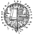
제 3 도는 제 1 도의 구형 본체의 확대 종단 정면도.3 is an enlarged vertical front view of the spherical body of FIG.
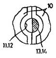
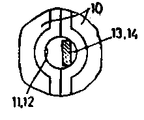
제 4 도는 (a), (b), (c)는 제 1 도의 극축의 편심축부의 각예를 도시한 확대 횡 단면도.(A), (b), (c) is an enlarged horizontal cross sectional view which shows each example of the eccentric shaft part of the polar axis of FIG.
제 5 도는 제 1 도의 편심축부의 관통용 환공(丸孔)의 구분의 다른 예를 도시한 확대 횡 단면도.FIG. 5 is an enlarged horizontal cross-sectional view showing another example of the division of a through hole for eccentric shaft portion in FIG.
제 6 도는 구형본체의 내부기구의 다른 예를 도시한 확대 종단 정면도.6 is an enlarged vertical front view showing another example of the internal mechanism of the spherical body.
제 7 도는 제 6 도의 I - I 선의 단면도이고, 구형본체의 도시를 생략한 것.7 is a cross-sectional view taken along the line I-I of FIG. 6, and the illustration of a spherical body is omitted.
* 도면의 주요부분에 대한 부호의 설명* Explanation of symbols for main parts of the drawings
5 : 자오선테 6 : 수평축5: meridian frame 6: horizontal axis
7 : 극축 10 : 반구형 부재7
11, 12 : 환공 13,14 : 편심축부11, 12:
16 : 회전지지체 21 : 회전축16: rotating support 21: rotating shaft
본 발명은 교제용등에 사용되는 지구의, 월구의, 천구의 등의 구상표시 장치에 관한 것이다.The present invention relates to a spherical display device such as a globe, a moon, a celestial sphere, and the like used for companionship.
종래의 지구의는 그의 대부분이 구상본체의 남북 즉, 상하를 관통하는 축을 반원호상 또는 원형한상의 지지테에 의해 회동자유롭게 지지되는 구조이었다. 또, 특공소 55-20234호 공부기재의 지구의와 같이, 지구의 본체를 투명의 반구상 캡슐에 수납하고, 이 캡슐을 대좌의 수용프레임에 수용지지시키는 것도 있다.The conventional earth is a structure in which most of them are freely supported by the support frame of the semicircular arc or the circular limit on the north and south of the spherical body, that is, the upper and lower axes. In addition, similar to that of the earth of the study publication 55-20234, the main body of the earth is housed in a transparent hemispherical capsule, and the capsule is accommodated and supported by the accommodating frame of the pedestal.
상기의 남북을 관통하는 축을 중심으로 회전하도록한 것은 축을 지지하는 지지테가 있음으로해서 관찰이 방해되고, 특히 화부의 남극 부분의 관찰이 곤란하다.Rotation about the axis penetrating the north-south above is supported by the support frame supporting the axis, which obstructs the observation, and in particular, it is difficult to observe the south pole part of the fire department.
또, 특공소 55-20234호 공보기재의 것은 지구의 본체를 자유로운 방향으로 할 수가 있다고 하는 특징은 있으나, 지구의 자전운동을 설명하는 경우에 극히 불편하고, 지구의 본체의 표면이 캡슐의 내면의 돌기둥에 직접 접촉하기 때문에, 표면이 상처나기 쉬운 등의 문제가 있었다.In addition, the special publication 55-20234 has the characteristic that the main body of the earth can be moved freely, but it is extremely inconvenient to explain the rotational movement of the earth, and the surface of the main body of the earth directly touches the inner pillar of the capsule. There was a problem that the surface was easily scratched because of contact.
상기의 문제점을 해결하기 위하여, 본 발명은 적당한 지지수단으로 지지시킨 극축에 회전지지체를 설치하고, 이 회전지지체의 양측에 극축과 직교하는 축심을 중심으로 해서 자유롭게 회전하는 반구형 부재를 설치해서, 이 양반구형부재의 의해 구형 본체를 구성하고, 상기 극축의 단부 부근에는 한쪽의 반구형 부재의 주연의 통과를 허용하는 편심축부를 설치하고, 부형본체의 외표면에 지도등의 표시를 시행한 것이다.In order to solve the above problems, the present invention is to provide a rotating support on the pole shaft supported by a suitable support means, and to provide a hemispherical member that rotates freely about an axis center orthogonal to the pole axis on both sides of the rotary support, The spherical body is formed by the two hemispherical members, and an eccentric shaft portion is provided near the end of the polar axis to allow the peripheral passage of one hemispherical member, and a map or the like is displayed on the outer surface of the shaped body.
본 발명은 상기의 구성이기 때문에, 지구의의 경우, 남극이 아래에 있는 상태에서 극축의 편심축부가 없는 측에 있는 반구형 부재를 극축과 직교하는 축심을 중심으로 180°회전시켜, 이어서 구형 본체를 극축을 중심으로 180°회전시켜서 편심축부가 없는 측에 온 반구형 부재를 극축에 직교하는 축심을 중심으로 180°회전시키면 남극이 위로되고, 종래의 지구의로는 관찰이 곤란하였던 남극부분이 충분히 관찰된다. 또, 경사 자유로운 자오선태에 극축을 설치한 경우는 북극을 위로하고 극축을 자오선테와 같이 경사시켜, 구형본체를 극축을 중심으로 회전시키면 일반의 지구의와 같이 지축이 경사된 지구의 자전을 설명할 수 있다.Since the present invention has the above-described configuration, in the case of the earth, the hemispherical member on the side without the eccentric shaft portion of the polar axis is rotated by 180 ° about an axis center orthogonal to the polar axis in the state where the south pole is below, and then the spherical main body is polar axis. If the hemispherical member on the side without the eccentric shaft part is rotated 180 degrees about the axis center orthogonal to the polar axis, the south pole is upward, and the south pole part which was difficult to observe by the conventional earth can be sufficiently observed. In addition, if the polar axis is installed in the free meridian, the pole is up and the polar axis is inclined like the meridian frame. When the spherical body is rotated around the polar axis, the rotation of the earth with the inclined axis can be explained as in the general earth. have.
제 1 도 내지 제 4 도에 도시한 본 발명의 대표적인 실시예에 있어서, 1은 대좌이고, 이 대좌(1)위에 수직의 지주(2)를 고정하고, 이 지주(2)위에 상향반원호상의 지지테(3)의 중심부를 고정한다.In the exemplary embodiment of the present invention shown in FIGS. 1 to 4, 1 is a pedestal, and a
또한, 지지테(3)의 내측에는 반원호상의 자오선테(5)를 지지테(3)와의 사이에 약간의 간극이 존재하는 상태로 위치시켜서 그의 양단과 지지테(3)의 양단을 수평의 축(6)에 의해 결합하고 자오선테(5)를 축(6)을 중심으로해서 경사 자유롭게 한다.Moreover, inside the
상기 자오선테(5)의 중심상에 극축(7)을 설치한다. 즉, 이 극축(7)의 하단의 작은 수나사(8)를 자오선테(5)의 중심구멍에 삽입해서 제 3 도와 같이 너트(9)에 고정한다.The
극축(7)은 자오선테(5)와 같이 축(6)을 중심으로 해서 360°회전할 수 있으나 이하의 구성설명에서는 제 1 도 내지 제 3 도와 같이 극축(7)이 자오선테(5)위에 수직으로 서있는 것으로서 설명한다.The
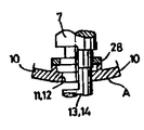
A는 중공의 구형본체이고 좌우한쌍의 반구형부재(10)로 이루어지고, 상기 극축(7)의 상하단은 구형본체(A)의 환공(11,12)에 회동자유로 끼워 맞춘 편심축부(13,14)로 되어있으나, 이 축부(13,14)는 제 4 도의 (a), (b), (c)와 같이 환공(11,12)의 반의 부분에 끼워 맞추도록 반원형, 편심핀형, 편평형등의 형상으로 반구형부재(10)의 환공(11,12)의 반의 부분(11',12')내에 끼워 넣도록 편심되어 있다.A is a hollow spherical body and consists of a pair of left and right
극축(7)의 중산부의 외측에, 회전지지체(16)를 상하의 축받이(17,18)를 통해서 설치하고, 이 지지체(16)의 중앙양측에는 극축(7)과 직교하는 지지통(20)을 일체로 설치하고, 이 양 지지통(20)에 상기 양반구형부재(10)의 내측중심에 고정된 회전축(21)을 회동자유롭게 설치하고, 또한 적당한 뽑혀나옴 방지를 시행한다. 또, 양 지지통(20)의 외측에는 스프링재로 이루어지는 클릭스톱(23)을 설치하고, 그의 외단의 걸어맞춤 볼록부(24)를 반구형부재(10)의 내측의 복수의 오목부(25)에 걸거나 벗김으로써 부재(10)가 일정각도마다 임시고정되도록 한다.On the outer side of the middle part of the
상기 극축(7)은 구형본체(A)와 같이 수평의 축(6)을 중심으로 해서 360°회전할 수 있으나, 자오선테(5)와 같이 회전하기 때문에, 자오선테(5)와 반대의 측의 지지대(16)의 단부의 지름을 대경의 평형장치(27)로서 중심점이 본체(A)의 중심이 되도록 한다.The
또, 제 3 도와 같이 환공(11,12)의 내면과 편심축부(13,14)가 직접 접촉하는 구조이고, 축부(13,14)가 금속이고 본체(A)가 플라스틱인 경우, 환공(11,12)이 조기에 마모되는 염려가 있다.In addition, as shown in the third diagram, the inner surfaces of the
상기의 문제를 해결하기 위해 제 5 도와 같이 환공(11,12)의 내측에 금속성의 보강링(28)을 고정하면 좋다.In order to solve the above problem, the
상기 실시예에 있어서, 구형본체(A)를 지구의로 했을 경우, 본체(A)의 상부 환공(11)의 중심을 북극, 하부의 환공(12)의 중심을 남극으로 하고, 본체(A)의 갈라진 금, 즉 좌우의 반구형부재(10)의 합침에 의한 선은 남극과 북극을 지나는 자오선테에 따르고 있다.In the above embodiment, when the spherical body A is the earth, the center of the upper
따라서의 지구의의 경우, 예컨대 좌우의 부재(10)의 합쳐진 선을 경도 0°도와 180°로 해서 본체(A)의 표면에 지도를 표시한다.Therefore, in the case of the earth, for example, a map is displayed on the surface of the main body A with the combined lines of the left and
제 3 도에 있어서, 좌측의 부재(10)는 그의 환공(11,12)의 반의 부분에 편심축부(13,14)가 없기 때문에, 회전축(21)을 중심으로해서 자유로 회전한다. 따라서 좌측의 부재(10)는 남극과 북극을 반전시킬 수가 있다. 그러나 우측의 부재(10)는 극축(7)의 편심축부(13,14)와 환공(11,12)의 우측의 끼워 맞춤에 의해 회전축(21)과 같이 회전할 수 없기 때문에, 상기와 같이 좌측의 부재(10)를 반전시 킨 후, 본체(A)를 극축(7)을 중심으로 180°반전시켜 이어서 좌측으로된 부재(10)를 회전축(21)과 같이 180°반전시키면 본체(A)는 회전축(21)을 중심으로 해서 완전히 반전하여 남극이 위로되고, 남극의 관찰이 용이하게 된다.3, since the
상기의 실시예에서는 극판(30)은 고정되어 있기 때문에 극부근의 지도는 표시되지 않는다.In the above embodiment, since the
제 6 도, 제 7 도의 실시예는 본체(A)를 반전시키면 극부근의 지도도 자동적으로 교체되도록 한 것이다.6 and 7 invert the main body A so that the map near the pole is also automatically replaced.
이 실시예도 외부의 구성은 상기의 대표적 실시예와 같고, 본체(A)의 내부 구조만이 다른 것이다.The external structure of this embodiment is also the same as that of the above-mentioned representative embodiment, and only the internal structure of the main body A is different.
이 실시예의 경우, 극축(7)의 상단은 본체(A)내에서 끝나있다.In the case of this embodiment, the upper end of the
양반구형부재(10)의 극부근의 내측에는 각각 가동부재(32)를 배치하고, 이들의 각 가동부재(32)와 반구형부재(10)의 내측을 각각 한쌍의 링크(33)로 연결해서, 각 부재(32)가 평행이동하도록 하고, 이 각 가동부재(32)의 외단에는 환공(11,12)내에 출몰하는 반원형의 극형성부(34)를 설치하고, 이 형성부(34)의 외단면은 환공(11,12)내에 형성부(34)가 끼워넣어졌을때 본체(A)의 외측구면의 일부를 이루고, 또한 북극 및 남극의 지도를 표시한다.The
본체(A)내의 회전지지체(16)는 그의 외주 및 지지통(20)에 면하는 단면을 가이드면으로하여 각각 둘레방향의 가이드홈(36)과 단면의 가이드홈(37)을 설치하고, 상기 각 가동부재(32)의 내단의 각 한쌍의 미끄럼부(38,39)를 각 가이드홈(36,37)에 미끄러져 움직이기 자유롭게 걸어 맞춘다.The
상기의 실시예에 있어서, 제 6 도의 상부에 위치하고 있는 양 가동부재(32)의 각 극형성부(34)는 상부의 환공(11)내에 있고, 동 형성부(34)의 상단면은 본체(A)의 외표면과 일치하고, 상부가 북극인 경우는 북극의 지도가 표시되어 있다.In the above embodiment, each
또, 하위의 양 가동부재(32)의 선단의 형성부(34)는 본체(A)내에 들어가 있고, 또한 극축(7)의 양측에 위치하고 있다.Moreover, the
상기의 상태에서 제 6 도의 좌측의 반구형부재(10)를 회전축(21)을 중심으로 180°회전시키면, 하위에 있던 양 가동부재(32)의 미끄럼부(38,39)가 가이드홈(36,37)에 따라서 내측으로 기울면서 외측으로도 기울기 때문에, 부재(10)가 180°회전해서 남극이 상향으로 되면 남극용의 가동부재(32)의 극형성부(34)가, 위로된 환공(12)의 한쪽부분으로 끼워 넣어진다.In the above state, when the
이어서, 본체(A)를 극축(7)을 중심으로 180°회전시켜, 좌측으로된 부재(10)를 회전축(21)을 중심으로 180°회전시키면 위로된 환공(12)내에 좌우의 극형성부 (34)가 끼워 넣어져서 완전하게 형성된 남극이 이루어진다.Subsequently, the main body A is rotated 180 ° about the
상기 실시예는 극축(7)과 직교하는 좌우의 회전축(21)을 중심으로 각 반구형부재(10)가 회전하는 예를 표시하였으나, 회전축(21)대신에 고정축을 중심으로 부재가 회전하도록 한 것이나 극축(7)의 양측이 가이드부에 설치된 복수의 가이드 로울러에 따라서 부재(10)가 회전하는 것등도 생각된다. 요컨대 극축(7)의 양측의 반구형부재(10)가 극축(7)과 직교하는 회전축을 중심으로 360°회전하도록 하면 좋다.Although the above embodiment shows an example in which each
또, 상기 실시예는 극축(7)을 자오선테(5)에 고정해서, 극축(7)을 자오선테(5)와 같이, 축(6)을 중심으로 경사시킬 수 있는 지지수단을 표시하였으나, 자오선테(5)나 지지테(3)를 없애고 극축(7)을 지주(2)상에 직접 고정하든지, 극축(7)의 하단을 직접 무엇인가의 대 위에 고정하는 경우등이 있다. 또, 반구형부재(10)의 북극과 남극의 부분의 환공(11,12)의 중간점, 즉 제 2 도의 쇄선으로 도시하는 부분, 예컨대 지구의의 경우, 자오선과 적도의 교점에 양부재(10)에 미치는 환공을 설치하고, 구형본체(A)를 갈라진 선에 따라서 90°마다 회전시켜서, 극축(7)을 중심으로 회전시킬 수 있도록 하는 경우도 있다.In addition, the above embodiment has shown the support means for fixing the
본 발명은 상기와 같이 적당한 지지수단으로 지지시킨 자오선테에 하단을 고정시킨 극축에 회전지지체를 설치하고, 이 회전지지체의 양측에 극측에 직교하는 축심을 중심으로 해서 자유롭게 회전하는 반구형 부재를 설치하고, 이 양반구형부재에 의해 구형본체를 구성하고, 극축의 단부 부근에는 한쪽의 반구형 부재의 주연의 통과를 허용하는 편심 축부를 설치해서 편심축부가 없는 측에 있는 반구형 부재는 극축에 방해되는 일없이, 극축과 직교하는 축심을 중심으로 180°회전시킬 수 있도록 하였기 때문에, 이것을 이용해서 한쪽의 반구형부재를 180°회전시켜, 이어서 구형본체를 극축을 중심으로 180°회전시켜서, 편심축부가 없는 측에 온 반구상 부재를 극축에 직교하는 축심을 중심으로 180°회전시키면 남극이 위로되고, 종래의 지구의에서는 관찰이 곤란했던 남극부분이 충분하게 관찰된다.The present invention is provided with a rotary support on the pole shaft fixed to the lower end on the meridian frame supported by a suitable support means as described above, and on both sides of the rotary support to provide a hemispherical member that rotates freely around an axis center orthogonal to the pole side The hemispherical member is constituted by the two hemispherical members, and an eccentric shaft portion is provided near the end of the polar shaft to allow the peripheral passage of one hemispherical member, and the hemispherical member on the side without the eccentric shaft portion is not obstructed by the polar axis. Since it is possible to rotate 180 ° about the axis centered perpendicular to the polar axis, this can be used to rotate one hemispherical member by 180 °, and then rotate the spherical body by 180 ° about the polar axis. Rotating the whole hemispherical member 180 ° around its center perpendicular to the polar axis will raise the South Pole and observe it in the conventional earth. This difficult Antarctic part is fully observed.
또, 실시예와 같이 경사 자유로운 자오선테를 설치해서, 이 자오선테에 극축의 하단을 고정시킨 경우는, 북극을 위로해서, 극축을 자오선테와 같이 경사시켜, 구형본체를 극축을 중심으로 회전시키면 일반의 지구의와 같이 지축이 경사된 지구의 자전을 설명할 수 있다.In addition, when the meridian frame is inclined freely as in the embodiment, and the lower end of the polar axis is fixed to the meridian frame, the polar axis is inclined like the meridian frame and the spherical body is rotated about the polar axis. Can explain the rotation of the earth tilted like the earth in general.
Claims (1)
Applications Claiming Priority (3)
| Application Number | Priority Date | Filing Date | Title |
|---|---|---|---|
| JP293865 | 1986-12-09 | ||
| JP?61-293865 | 1986-12-09 | ||
| JP61293865A JPS63144385A (en) | 1986-12-09 | 1986-12-09 | Spherical display device |
Publications (2)
| Publication Number | Publication Date |
|---|---|
| KR880008222A KR880008222A (en) | 1988-08-30 |
| KR910004726B1 true KR910004726B1 (en) | 1991-07-10 |
Family
ID=17800153
Family Applications (1)
| Application Number | Title | Priority Date | Filing Date |
|---|---|---|---|
| KR1019870013138A KR910004726B1 (en) | 1986-12-09 | 1987-11-21 | Equipment of indicate at globular form |
Country Status (5)
| Country | Link |
|---|---|
| US (1) | US4752228A (en) |
| EP (1) | EP0271226B1 (en) |
| JP (1) | JPS63144385A (en) |
| KR (1) | KR910004726B1 (en) |
| DE (1) | DE3772345D1 (en) |
Families Citing this family (6)
| Publication number | Priority date | Publication date | Assignee | Title |
|---|---|---|---|---|
| US5030100A (en) * | 1989-09-05 | 1991-07-09 | Hilderman Garry M | Environmental display system |
| US6176705B1 (en) * | 1999-09-24 | 2001-01-23 | Shawn Garvey | Solar system teaching aid |
| US6726484B2 (en) * | 2002-05-15 | 2004-04-27 | Replogle Globes, Inc. | Globe stand construction |
| US6773262B1 (en) * | 2003-10-23 | 2004-08-10 | Alvin S. Blum | World globe with detail display |
| US9373270B2 (en) * | 2009-10-15 | 2016-06-21 | Douglas Wayne Miyazaki | Pelvic surgery training model |
| CN103871316A (en) * | 2012-12-12 | 2014-06-18 | 李一波 | Double-shaft tellurion capable of rotating for 360 degrees |
Family Cites Families (8)
| Publication number | Priority date | Publication date | Assignee | Title |
|---|---|---|---|---|
| US651804A (en) * | 1900-03-23 | 1900-06-12 | George L Houghton | Globe and fixture therefor. |
| US2483932A (en) * | 1945-03-12 | 1949-10-04 | Saint Paul Inst | Globe mount |
| CH346051A (en) * | 1955-04-14 | 1960-04-30 | Antoine Bartholdi Henri | Geographic Globe |
| US2958959A (en) * | 1958-03-03 | 1960-11-08 | Rand Mcnally & Co | Globe mounting |
| CH352169A (en) * | 1958-05-05 | 1961-02-15 | Antoine Bartholdi Henri | Graduated arc of latitudes with vernier cursor-pointer |
| US2957252A (en) * | 1959-12-11 | 1960-10-25 | William A Pain | Globe support and orienting means |
| US3055123A (en) * | 1961-04-24 | 1962-09-25 | Tigrett Ind Inc | Globe |
| JPS5520234A (en) * | 1978-07-27 | 1980-02-13 | Denki Kagaku Kogyo Kk | Production of polycrystalline alumina fiber |
-
1986
- 1986-12-09 JP JP61293865A patent/JPS63144385A/en active Granted
-
1987
- 1987-02-19 US US07/016,711 patent/US4752228A/en not_active Expired - Lifetime
- 1987-11-12 DE DE8787309997T patent/DE3772345D1/en not_active Expired - Lifetime
- 1987-11-12 EP EP87309997A patent/EP0271226B1/en not_active Expired - Lifetime
- 1987-11-21 KR KR1019870013138A patent/KR910004726B1/en not_active IP Right Cessation
Also Published As
| Publication number | Publication date |
|---|---|
| JPH0481794B2 (en) | 1992-12-24 |
| US4752228A (en) | 1988-06-21 |
| EP0271226B1 (en) | 1991-08-21 |
| EP0271226A1 (en) | 1988-06-15 |
| JPS63144385A (en) | 1988-06-16 |
| KR880008222A (en) | 1988-08-30 |
| DE3772345D1 (en) | 1991-09-26 |
Similar Documents
| Publication | Publication Date | Title |
|---|---|---|
| KR910004726B1 (en) | Equipment of indicate at globular form | |
| ES2029559T3 (en) | BEARING WITH INFORMATION COLLECTOR. | |
| FR2431070A1 (en) | ROLLING BEARING | |
| US4671669A (en) | Solar system clock | |
| DK179990A (en) | BALL UNIT AND BALL COVER | |
| JP2003270364A (en) | Magical rotational bezel | |
| FR2506875A1 (en) | UNIVERSAL JOINT | |
| KR880009228A (en) | Flexible Treeport Universal Joint | |
| US2343173A (en) | Globe mounting | |
| JP2002072865A (en) | Earth movement globe | |
| JPH0341492A (en) | Sphere display tool | |
| FR2470917A1 (en) | INSTRUMENT HOLDER | |
| JP2001117485A (en) | Terrestrial globe | |
| GB2446426A (en) | Photograph based globe with outer sphere layer representing atmosphere. | |
| KR920002228Y1 (en) | The globe institutional a watch | |
| JPS6350677Y2 (en) | ||
| JP3084096U (en) | A globe that eliminates the rotation axis and enables free rotation | |
| BR112018070037B1 (en) | IMPROVED PEDESTRIAN GUIDANCE STRUCTURE | |
| KR930004831A (en) | Light and shadow clock | |
| JPH02214886A (en) | Constellation guide device | |
| JPH07239652A (en) | Sphere display device | |
| JP3018999U (en) | Omni-directional globe | |
| JPH019975Y2 (en) | ||
| JP2002040929A (en) | Rolling terrestrial globe with fresnel lens | |
| KR880001070B1 (en) | The earth globe of rotation from the earthmagnetic force and gravity |
Legal Events
| Date | Code | Title | Description |
|---|---|---|---|
| A201 | Request for examination | ||
| E902 | Notification of reason for refusal | ||
| G160 | Decision to publish patent application | ||
| E701 | Decision to grant or registration of patent right | ||
| GRNT | Written decision to grant | ||
| FPAY | Annual fee payment |
Payment date: 19980609 Year of fee payment: 8 |
|
| LAPS | Lapse due to unpaid annual fee |