KR910002737B1 - Combustion device - Google Patents
Combustion device Download PDFInfo
- Publication number
- KR910002737B1 KR910002737B1 KR1019860011068A KR860011068A KR910002737B1 KR 910002737 B1 KR910002737 B1 KR 910002737B1 KR 1019860011068 A KR1019860011068 A KR 1019860011068A KR 860011068 A KR860011068 A KR 860011068A KR 910002737 B1 KR910002737 B1 KR 910002737B1
- Authority
- KR
- South Korea
- Prior art keywords
- blower
- combustion
- control valve
- amount
- control circuit
- Prior art date
Links
Images


Classifications
-
- F—MECHANICAL ENGINEERING; LIGHTING; HEATING; WEAPONS; BLASTING
- F23—COMBUSTION APPARATUS; COMBUSTION PROCESSES
- F23N—REGULATING OR CONTROLLING COMBUSTION
- F23N1/00—Regulating fuel supply
- F23N1/02—Regulating fuel supply conjointly with air supply
-
- F—MECHANICAL ENGINEERING; LIGHTING; HEATING; WEAPONS; BLASTING
- F23—COMBUSTION APPARATUS; COMBUSTION PROCESSES
- F23N—REGULATING OR CONTROLLING COMBUSTION
- F23N1/00—Regulating fuel supply
- F23N1/02—Regulating fuel supply conjointly with air supply
- F23N1/022—Regulating fuel supply conjointly with air supply using electronic means
-
- F—MECHANICAL ENGINEERING; LIGHTING; HEATING; WEAPONS; BLASTING
- F23—COMBUSTION APPARATUS; COMBUSTION PROCESSES
- F23N—REGULATING OR CONTROLLING COMBUSTION
- F23N2225/00—Measuring
- F23N2225/08—Measuring temperature
-
- F—MECHANICAL ENGINEERING; LIGHTING; HEATING; WEAPONS; BLASTING
- F23—COMBUSTION APPARATUS; COMBUSTION PROCESSES
- F23N—REGULATING OR CONTROLLING COMBUSTION
- F23N2225/00—Measuring
- F23N2225/08—Measuring temperature
- F23N2225/16—Measuring temperature burner temperature
-
- F—MECHANICAL ENGINEERING; LIGHTING; HEATING; WEAPONS; BLASTING
- F23—COMBUSTION APPARATUS; COMBUSTION PROCESSES
- F23N—REGULATING OR CONTROLLING COMBUSTION
- F23N2225/00—Measuring
- F23N2225/08—Measuring temperature
- F23N2225/18—Measuring temperature feedwater temperature
-
- F—MECHANICAL ENGINEERING; LIGHTING; HEATING; WEAPONS; BLASTING
- F23—COMBUSTION APPARATUS; COMBUSTION PROCESSES
- F23N—REGULATING OR CONTROLLING COMBUSTION
- F23N2233/00—Ventilators
- F23N2233/06—Ventilators at the air intake
- F23N2233/08—Ventilators at the air intake with variable speed
-
- F—MECHANICAL ENGINEERING; LIGHTING; HEATING; WEAPONS; BLASTING
- F23—COMBUSTION APPARATUS; COMBUSTION PROCESSES
- F23N—REGULATING OR CONTROLLING COMBUSTION
- F23N2235/00—Valves, nozzles or pumps
- F23N2235/12—Fuel valves
- F23N2235/14—Fuel valves electromagnetically operated
-
- F—MECHANICAL ENGINEERING; LIGHTING; HEATING; WEAPONS; BLASTING
- F23—COMBUSTION APPARATUS; COMBUSTION PROCESSES
- F23N—REGULATING OR CONTROLLING COMBUSTION
- F23N2235/00—Valves, nozzles or pumps
- F23N2235/12—Fuel valves
- F23N2235/16—Fuel valves variable flow or proportional valves
-
- F—MECHANICAL ENGINEERING; LIGHTING; HEATING; WEAPONS; BLASTING
- F23—COMBUSTION APPARATUS; COMBUSTION PROCESSES
- F23N—REGULATING OR CONTROLLING COMBUSTION
- F23N5/00—Systems for controlling combustion
- F23N5/02—Systems for controlling combustion using devices responsive to thermal changes or to thermal expansion of a medium
- F23N5/10—Systems for controlling combustion using devices responsive to thermal changes or to thermal expansion of a medium using thermocouples
-
- F—MECHANICAL ENGINEERING; LIGHTING; HEATING; WEAPONS; BLASTING
- F23—COMBUSTION APPARATUS; COMBUSTION PROCESSES
- F23N—REGULATING OR CONTROLLING COMBUSTION
- F23N5/00—Systems for controlling combustion
- F23N5/18—Systems for controlling combustion using detectors sensitive to rate of flow of air or fuel
Abstract
내용 없음.No content.
Description
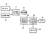
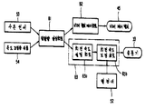
제1도는 본 발명에 관한 제어회로의 블럭도.1 is a block diagram of a control circuit according to the present invention.
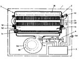
제2도는 가스탕비기의 개략도.2 is a schematic diagram of a gas stove.
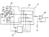
제3도는 회전속도 검출회로의 전기 회로도.3 is an electrical circuit diagram of a rotation speed detection circuit.
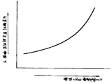
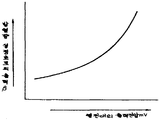
제4도는 송풍기의 회전속도와 회전속도 검출회로의 출력과의 관계를 나타낸 그래프.4 is a graph showing the relationship between the rotational speed of the blower and the output of the rotational speed detection circuit.
제5도는 회전속도 검출회로의 출력에 대하여 설정된 비례제어밸브의 통전량을 나타낸 그래프.5 is a graph showing the energization amount of the proportional control valve set with respect to the output of the rotational speed detection circuit.
제6도는 회전속도 검출회로의 출력에 대하여 설정된 열전대의 적정한 출력치를 나타낸 그래프.6 is a graph showing an appropriate output value of a thermocouple set for the output of the rotational speed detection circuit.
제7도는 본 발명의 제2실시예를 나타낸 제어회로의 블럭도.7 is a block diagram of a control circuit showing a second embodiment of the present invention.
제8도는 비례밸브 제어회로의 출력에 대하여 설정된 열전대의 적정한 출력치를 나타낸 그래프.8 is a graph showing an appropriate output value of a thermocouple set with respect to the output of a proportional valve control circuit.
제9도는 본 발명의 제3실시예를 나타낸 제어회로의 블럭도.9 is a block diagram of a control circuit showing a third embodiment of the present invention.
제10도는 본 발명의 제4실시예를 나타낸 제어회로의 블럭도.10 is a block diagram of a control circuit showing a fourth embodiment of the present invention.
제11도는 발열량 설정회로의 출력에 대하여 설정된 열전대의 적정한 출력치를 나타낸 그래프이다.11 is a graph showing an appropriate output value of the thermocouple set with respect to the output of the heat generation amount setting circuit.
* 도면의 주요부분에 대한 부호의 설명* Explanation of symbols for main parts of the drawings
1 : 가스탕비기 31 : 버너1: gas stove 31: burner
33 : 송풍기 42 : 가스공급 배관33: blower 42: gas supply piping
45 : 비례제어밸브 52 : 열전대45: proportional control valve 52: thermocouple
53 : 수온센서 54 : 온도조절용 볼륨53: water temperature sensor 54: temperature control volume
61 : 송풍기제어회로 62 : 회전속도 검출회로61: blower control circuit 62: rotational speed detection circuit
63 : 비례밸브제어회로63: proportional valve control circuit
본 발명은 버너에 연료를 공급하는 비례제어밸브와 버너에 연소용 공기를 공급하는 송풍기를 구비한 연소장치에 관한 것이다.The present invention relates to a combustion apparatus having a proportional control valve for supplying fuel to a burner and a blower for supplying combustion air to the burner.
가스나 석유 등의 연료를 비례제어밸브에 의한 연료의 공급량에 따라 버너에 공급함과 동시에 송풍기에 의하여 연소용 공기를 버너에 공급하는 연소식 탕비기, 연소식 난방장치 등의 연소장치가 사용되고 있다.Combustion apparatuses, such as a combustor and a heating heater, which supply fuel such as gas or petroleum to the burner according to the amount of fuel supplied by the proportional control valve and supply the combustion air to the burner by a blower, are used.
종래 이 종류의 장치는 사용자에 의하여 설정되는 발열량 설정수단(예를 들어 온도설정수단)에 따라 비례제어밸브에 의한 연료의 공급량이 설정되어 버너에 연료가 공급됨과 동시에 송풍기에 의해 버너에 공기가 공급되고, 버너에서 연료의 연소가 행하여 진다. 이때, 송풍기에 의한 연소용 공기의 공급량은 버너의 화염상태를 검출하는 연소센서(예를 들어 열전대)의 출력에 따라 제어된다.Conventionally, in this type of device, the amount of fuel supplied by the proportional control valve is set according to the calorific value setting means (for example, the temperature setting means) set by the user, the fuel is supplied to the burner, and the air is supplied to the burner by the blower. Then, fuel is burned in the burner. At this time, the supply amount of combustion air by the blower is controlled in accordance with the output of the combustion sensor (for example, thermocouple) for detecting the flame state of the burner.
그러나 종래의 연소장치는, 상기와 같이 비례제어밸브를 제어하는 회로와, 송풍기를 제어하는 회로가 각각 독립된 별개의 회로로 되어있기 때문에, 예를 들어, 발열량 설정수단을 변화시켰을 경우, 비례제어밸브의 개방도는 발열량 설정수단의 변화에 신속하게 대응하여 변화하나, 송풍기에 의한 연소용 공기의 공급량은, 먼저 비례제어밸브의 개방도의 변화에 의한 화염의 변화를 연소센서가 검출하고, 그 연소센서의 출력변화에 따라 송풍기의 송풍량을 변화시키기 때문에, 발열량 설정수단의 변화에 대한 송풍기의 응답성이 매우 나쁘다는 문제점을 가지고 있었다.However, in the conventional combustion apparatus, since the circuit for controlling the proportional control valve and the circuit for controlling the blower are independent circuits as described above, for example, when the calorific value setting means is changed, the proportional control valve The opening degree of is changed rapidly in response to the change of the calorific value setting means, but the supply amount of combustion air by the blower firstly detects the flame change caused by the change of the opening degree of the proportional control valve, and the combustion Since the blower volume of the blower is changed in accordance with the output change of the sensor, the blower has a problem that the response of the blower to the change of the heat generation amount setting means is very bad.
본 발명은 상기 사정을 감안하여 이루어진 것으로 그 목적은 발열량 설정수단의 변화에 적응하여 비례제어밸브에 의한 연료의 공급량과 송풍기에 의한 연소용 공기의 공급량을 신속하게 대응시킴과 동시에, 공연비를 미리 설정된 값으로 유지할 수 있는 연소장치를 제공하는 것이다.SUMMARY OF THE INVENTION The present invention has been made in view of the above circumstances, and an object thereof is to adapt the change of the heat generation amount setting means to quickly correspond the supply amount of fuel by the proportional control valve and the supply amount of combustion air by the blower, and to set the air-fuel ratio in advance. It is to provide a combustion apparatus that can be maintained at a value.
본 발명은 상기 목적을 달성하기 위하여 버너와, 이 버너에 연료를 공급하는 비례제어밸브와, 상기 버너에 연소용 공기를 공급하는 송풍기와, 상기 버너의 연소상태를 검지하는 연소센서와, 발열량 설정수단과, 이 발열량 설정수단의 설정상태에 따라 상기 비례제어밸브에 의한 연료 공급량 혹은 송풍기에 의한 연소용 공기의 공급량중 한쪽을 제어하는 제1제어회로와, 상기 발열량 설정수단의 설정상태 혹은 상기 제1제어회로에 의해 제어되는 비례제어밸브에서의 연료공급량 혹은 상기 송풍기에서의 연소용 공기의 공급량중의 어느 한쪽의 설정상태에 의하여, 상기 비례제어 밸브에서의 연료공급량 혹은 송풍기에서의 연소용 공기의 공급량중 다른쪽의 제어를 행하는 제2제어회로를 구비하고, 이 제2제어회로는, 상기 연소센서의 출력이 상기 발열량 설정수단 혹은 제1제어회로에 의해 제어되는 상기 비례제어밸브에서의 연료공급량 혹은 송풍기에서의 연소용 공기의 공급량중 어느 한쪽의 설정상태에 의하여 사전에 설정된 값이되도록 상기 제2제어회로에 의해 제어되는 비례제어 밸브에서의 연료 공급량 혹은 송풍기에서의 연소용공기의 공급량중 다른 한쪽을 보정제어하는 것을 기술적 수단으로 한다.In order to achieve the above object, the present invention provides a burner, a proportional control valve for supplying fuel to the burner, a blower for supplying combustion air to the burner, a combustion sensor for detecting a combustion state of the burner, and a calorific value setting Means for controlling one of the fuel supply amount by the proportional control valve or the supply amount of combustion air by the blower in accordance with the setting state of the heat generating amount setting means, and the setting state of the calorific value setting means or the first The fuel supply amount in the proportional control valve or the combustion air in the blower may be set by either one of the fuel supply amount in the proportional control valve controlled by the control circuit or the supply amount of combustion air in the blower. And a second control circuit for controlling the other of the supply amount, wherein the output of the combustion sensor is the heat generation amount. Controlled by the second control circuit so as to be a value set in advance by either the fuel supply amount in the proportional control valve or the supply amount of combustion air in the blower controlled by the water purification stage or the first control circuit. The technical means is to adjust and control the other of the fuel supply amount in the proportional control valve or the supply amount of combustion air in the blower.
상기 구성으로 이루어진 본 발명은 제1제어회로가 발열량 설정수단의 설정상태에 의하여 비례제어밸브에서의 연료 공급량 혹은 송풍기에서의 연소용 공기의 공급량중 어느 한쪽을 제어하여 발열량 설정수단을 변화시키면 신속하게 다른 한쪽이 발열량 설정수단의 변화에 따라 변화한다. 또 제2제어회로가 발열량 설정수단 혹은 한쪽의 설정상태에 따라 비례제어밸브에서의 연료공급량 혹은 송풍기에서의 연소용 공기 공급량중 다른한쪽을 제어하여, 발열량 설정수단을 변화시키면 발열량 설정수단 혹은 상기 한쪽의 변화에 따라 신속하게 다른한쪽이 변화한다. 이로서 발열량 설정수단의 변화에 따라 비례제어밸브에서의 연료 공급량과 송풍기에서의 연소용 공기의 공급량이 거의 동시에 적정한 값으로 설정되기 때문에 발열량 설정수단의 변화에 따라 발열량을 즉시 변화시킴과 동시에 화염을 항상 적정한 공연비로 연소시킬 수 있다.According to the present invention having the above-described configuration, the first control circuit quickly changes the calorific value setting means by controlling either the fuel supply amount in the proportional control valve or the supply amount of combustion air in the blower according to the setting state of the calorific value setting means. The other side changes depending on the change of the heat generation amount setting means. The second control circuit controls the other of the fuel supply amount in the proportional control valve or the combustion air supply amount in the blower in accordance with the heat generation amount setting means or one setting state, and if the heat generation amount setting means is changed, the heat generation amount setting means or the one side. The other side changes quickly as the change of. As a result, the amount of fuel supplied from the proportional control valve and the amount of combustion air supplied from the blower is set to an appropriate value at about the same time according to the change of the calorific value setting means. It can burn at an appropriate air-fuel ratio.
또, 화염이 적정한 공연비를 가지고 연소되지 않을 경우에는, 열전대의 출력이 사전에 어느 한쪽을 기준하여 설정된 값과는 다른값으로하게 되나 제2제어회로가 연료센서의 출력이 상기 한쪽에 의하여 설정된 값이 되도록 다른한쪽을 보정제어하기 때문에 버너에 공급되는 가스의 공급량이 항상 적절한 값으로 보정되어 화염은 적정한 공연비로 연소된다.If the flame is not combusted with an appropriate air-fuel ratio, the output of the thermocouple will be different from the value previously set on either basis, but the second control circuit will set the output value of the fuel sensor by the one side. Since the other side is corrected and controlled, the amount of gas supplied to the burner is always corrected to an appropriate value, and the flame is burned at an appropriate air-fuel ratio.
다음에 본 발명을 가스탕비기에 적용하였을 경우의 실시예를 도면에 의거하여 설명한다.Next, an embodiment in the case where the present invention is applied to a gas stove is described with reference to the drawings.
제2도는 가스탕비기의 개략도를 나타낸다. 이 가스탕비기(1)는 열교환부(2)를 구비한 연소부(3)와 가스공급로(4)와 전자제어회로(5)로서 이루어진다. 연소부(3)는 세라믹제의 표면 연소식 버너(31)를 구비한 연소실(32)과, 이 연소실(32)의 하부에 설치되고 버너(31)에 연소용 공기의 공급을 행하는 송풍기(33)를 구비한 연소용 공기 공급부(34)와, 연소실(32)의 위쪽에 설치되고 버너(31)에서 연소된 연소가스의 배기를 행하는 배기구(35)를 구비한다. 그리고 상기 열교환부(2)는 열교환 효율을 높히는 핀(21)과 급수관(22)으로 이루어지고 버너(31)과 배기구(35) 사이에 배치되어 급수관(22)의 상류로부터 이송되어 오는 물을 연소실(32)내의 연소가스와 열교환하여 탕수로서 유출한다.2 shows a schematic view of a gas stove. This gas scrubber 1 consists of the
가스공급로(4)는, 버너(31)의 상류에서 가스의 토출을 행하는 가수분출 노즐(41)과 가스분출노즐(41)에 가스를 공급하는 가스공급배관(42)의 상류측에 설치되어 통전 및 비통전에 의해 개폐되는 개폐밸브(43)와, 이 개폐밸브(43)의 하류측에 설치되어 가스의 유량의 조절을 행하는 조절밸브(44)와, 이 조절밸브(44)의 하류측에 설치되어 통전량에 따라 개구비가 가변하는 비례제어밸브(45)로 이루어진다.The
전자제어회로(5)는 착화시에 버너(31)의 상면에서 불꽃을 발생하는 스파크전극(51), 버너(31)의 위쪽에서 화염의 산소 공급 상태를 검지하는 연소센서인 열전대(52), 열교환부(2)의 급수관(22)의 유출부에 설치되어 수온의 검출을 행하는 수온센서(53), 사용자에 의하여 조작되고, 열교환부(2)의 급수관(22)으로부터 유출하는 수온의 설정을 행하는 온도조절용 볼륨(54), 송풍기(33), 개폐밸브(43), 비례제어밸브(45) 등의 구동 및 제어를 행한다.The electronic control circuit 5 includes a
다음에 비례제어밸브(45)의 개구비의 제어와 송풍기(33)에 의한 연소용 공기의 공급량의 제어를 제1도에 나타낸 블럭도에 의거하여 설명한다.Next, control of the opening ratio of the
수온센서(53)로부터의 출력신호와 온도조절용 볼륨(54)에 의하여 얻어지는 기준치를 비교 증폭하여, 송풍기(33)로의 통전량의 제어를 행함으로서 가스탕비기(1)로부터 얻어지는 탕수의 온도조절을 행하는 송풍기 제어회로(온도조절회로)(61)와, 송풍기(33)의 회전 속도를 검출함으로서 송풍기(33)에 의한 연소용 공기의 공급량의 검출을 행하는 회전속도 검출회로(62)와 그 회전 속도 검출회로(62)의 출력과 열전대(52)의 출력에 따라 비례제어밸브(45)의 개구비를 제어하고, 가스의 공급량을 제어하는 비례밸브 제어회로(63)를 구비한다.Comparatively amplifying the output signal from the
그리고 이 비례밸브 제어회로(63)는 회전속도 검출회로(62)의 출력에 따라 비례제어밸브(45)의 개방도를 설정하는 개방도 설정회로(63a)와 열전대(52)의 출력이 회전속도 검출회로(62)의 출력에 따라 설정값이 되도록 개방도 설정회로(63a)의 출력의 보정을 행하는 개방도 보정회로(63b)를 가지고 이루어진다.In addition, the proportional valve control circuit 63 outputs an opening degree setting circuit 63a for setting the opening degree of the
다음에 회전속도 검출회로(62)의 일실시예를 제3도에 의거하여 설명한다.Next, an embodiment of the rotational
본 실시예의 송풍기(33)는 구동축(33a)에 설치된 영구자석(33b)의 회전위치를 홀소자(33c)로 검출하는 무부러시 모터를 사용한다. 이 회전속도 검출회로(62)는, 영구자석(33b) 홀소자(33c) 코일(Co1∼Co4)로 이루어진 신호 발생부(62a)와 에널로그 스위치부(62b)와 디코우더(62c)와 전압 변환부(62d)로 이루어진다. 그리고 전압 변환부(62d)의 출력전압(V)은 제4도에 나타낸 바와 같이 송풍기(33)의 회전속도(N)에 따라 소정전압까지 비례적으로 변화된다.The
또, 비례밸브제어회로(63)의 개방도 설정회로(63a)는 제5도에 나타낸 바와 같이 회전속도 검출회로(62)가 출력하는 출력 전압(V)에 따라 비례제어밸브(45)로의 통전량(A)을 먼저 결정한다.In addition, the opening degree setting circuit 63a of the proportional valve control circuit 63 communicates with the
그리고 개방도 보정회로(63b)는 열전대(52)의 출력전압(mV)의 값이 제6도에 나타낸 바와 같이, 회전속도 검출회로(62)가 출력하는 출력전압(V)에 따라 설정된 값이 되도록 비례제어밸브(45)에 대한 통전량을 보정 제어한다.The opening degree correction circuit 63b has a value set according to the output voltage V output from the rotational
본 실시예의 가스 탕비기(1)는, 상기와 같은 전자 제어장치(5)를 구비함으로서 사용자가 온도조절용 볼륨(54)을 조작하여 가스탕비기(1)로부터 공급되는 탕수의 온도의 변화를 희망할 경우, 온도조절용 볼륨(54)의 변화에 따라서 온도조절용 볼륨(54)이 출력하는 기준 전압이 수온센서(53)의 출력에 대하여 신속하게 변화하기 때문에, 송풍기 제어회로(61)의 출력이 온도조절용 볼륨(54)의 조작에 따라 즉각적으로 변화하여 송풍기(33)의 회전속도를 변화시킨다. 상기에 의하여 송풍기(33)의 회전속도가 변화되면 회전속도 검출회로(62)의 출력전압(V)이 변화하기 때문에 개방도 설정회로(63a)가 비례제어밸브(45)로의 통전량(A)을 제5도에 따라 설정한다. 즉 조작자가 온도 조절용 볼륨(54)을 조작하면 송풍기(33)의 회전속도와 비례제어밸브(45)의 개방도가 실질적으로 동시에 변화하기 때문에 조작자가 희망하는 온도의 탕수가 가스탕비기(1)로부터 신속하게 공급된다. 또 이때 비례제어밸브(45)의 개방도와 송풍기(33)의 회전속도가 실질적으로 동시에 변화하기 때문에 송풍기(33)에 의한 연소용 공기의 공급량과 비례제어밸브(45)에 의한 가스의 공급량과의 비가 항상 적절한 값으로 유지되어 화염은 항상 적정한 공연비로 연소된다.The gas water purifier 1 of the present embodiment is provided with the electronic control device 5 as described above, so that the user can change the temperature of the hot water supplied from the gas water dispenser 1 by operating the
또 공급되는 가스의 성분 변화에 의하여 적정한 공연비로 연소되지 않을 경우, 또는 연소용공기의 흡입구와 배출구 등의 유로의 유통 저항이 증대하는 등 비례제어밸브(45)의 개방도에 따라 설정된 연소용 공기의 공급이 행하여 지지않고, 화염이 적정한 공연비로 연소하지 않을 경우 등이 발생할 가능성이 있다. 이 경우, 예를 들어 제6도에 있어서, 회전속도 검출회로(62)의 출력전압(V)의 값이 A1이고 열전대(52)의 출력전압(mV)의 값이 A2일때 가스과다이기 때문에 비례제어밸브(45)의 개방도를 작게하여 열전대(52)의 출력전압(mV)이 사전 설정된 값(A3)으로 되도록 비례제어밸브(45)로의 통전량(A)의 값을 보정한다. 또 회전속도 검출회로(62)의 출력전압(V)의 값이 A1이고 열전대(52)의 출력전압(mV)의 값이 A4일때는 가스 부족이기 때문에 비례제어밸브(45)의 개방도를 크게하고 열전대(52)의 출력전압(mV)이 사전 설정된 값(A3)으로 되도록 비례제어밸브(45)에의 통전량(A)의 값을 보정한다. 이에 따라 화염은 항상 적정한 공연비로 연소된다.In addition, when combustion does not occur at an appropriate air-fuel ratio due to a change in the gas component supplied, or the flow resistance of flow paths such as the inlet and outlet of the combustion air increases, the combustion air set according to the opening degree of the
한편 수온센서(53)가 가스탕비기(1)로부터 공급되는 탕수의 온도를 항상 감시하여 수온센서(53)가 검출한 온도와 온도조절용 볼륨(54)이 설정한 온도가 일치하도록 송풍기 제어회로(61)가 비례밸브 제어회로(63)를 제어함으로서, 비례제어밸브(45)의 개방도가 수온센서(53)의 온도 검출 속도에 실질적으로 대응하는 속도로 보정제어되어, 가스 탕비기(1)로부터 공급되는 탕수는 온도조절용 볼륨(54)에 의하여 설정된 온도로 보정된다.On the other hand, the
또한 송풍기 제어회로(61)에는, 가스탕비기(1)의 점화시 열전대(52)의 출력이 안정될때까지, 예를 들어 10초 동안 열전대(52)로부터의 입력을 소거(Cancel)하여 점화시에 있어서의 열전대(52)에 의한 공연비 제어의 오동작을 방지하도록 설치하였다.In addition, the blower control circuit 61 cancels the input from the
본 실시예에서는 송풍기(33)의 회전속도를 검출하는 수단으로 홀소자(33)를 사용하여 검출한 예를 나타냈으나, 회전 엔코더, 리졸버, 주파수 제네레이터 등에 의하여 검출하여도 된다.In the present embodiment, an example in which the
또, 본 실시예에서는 송풍기(33)에 의한 연소용 공기의 공급량을 검출하는 수단으로 송풍기(33)의 회전속도를 검출하는 예를 나타냈으나, 그 밖에 송풍기(33)의 하류에서 송풍기(33)의 풍압을 압력센서 등으로 검출하거나 송풍기(33)에 공급되는 통전량에 의해 송풍기(33)에 의한 연소용 공기의 공급량을 검출하여도 된다.In addition, in this embodiment, although the rotation speed of the
또한 송풍기(33)에 공급되는 통전량에 의하여 연소용 공기의 공급량을 검출하는 경우 비례밸브제어회로(63)의 입력측 혹은 출력측에 지연회로를 설치하여 완만하게 변화하는 송풍기(33)의 회전속도 변화의 도중에서 비례제어밸브(45)의 개방도를 변화시켜도 된다.In addition, when detecting the supply amount of combustion air by the amount of energization supplied to the
제7도에 본 발명의 제2실시예를 나타낸다. 본 실시예의 전자제어회로(5)는 수온센서(53)와 온도조절용볼륨(54)의 출력에 의하여 비례제어 밸브(45)로의 통전량의 제어를 행하는 비례밸브 제어회로(온도조절회로)(71)와 이 비례밸브 제어회로(71)로부터 비례제어밸브(45)에 공급되는 통전량을 검출하고 이 통전량과 열전대(52)의 출력과에 의해 송풍기(33)의 통전량 제어를 행하는 송풍기 제어회로(72)를 구비한다.7 shows a second embodiment of the present invention. The electronic control circuit 5 of this embodiment is a proportional valve control circuit (temperature regulating circuit) 71 which controls the amount of energization to the
그리고 이 송풍기 제어회로(72)는 비례밸브제어회로(71)의 출력에 따라 송풍기(33)로의 통전량을 설정하는 회전속도 설정회로(72a)와 열전대(52)의 출력전압(mV)이 제8도에 나타낸 바와 같이 비례밸브제어회로(71)의 출력(β)에 따라 설정된 값이 되도록 회전속도 설정회로(72a)의 출력을 보정하는 회전속도 보정회로(72b)로 이루어진다.The
또한 본 실시예에서는 비례제어밸브(45)의 개방도를 비례제어밸브(45)에 공급되는 통전량으로부터 검출하는 예를 나타냈으나, 비례제어밸브(45)의 밸브체의 변위량을 검출함으로서 검출하여도 된다.In addition, in this embodiment, although the opening degree of the
제9도에 본 발명의 제3실시예를 나타낸다.9 shows a third embodiment of the present invention.
상기 제2실시예에서는 온도조절용 볼륨(54)을 조작하는 경우, 송풍기(33)로의 통전량과 비례제어밸브(45)로의 통전량이 실질적으로 동시에 변화하는 예를 나타냈으나, 통상, 송풍기(33)의 응답속도는 비례제어밸브(45)의 응답속도에 비교하여 완만하게 변화하기 때문에 송풍기(33)와 비례제어밸브(45)에 대한 통전량(45)을 동시에 변화시켰을 경우, 온도조절용 볼륨(54)의 조작직 후는 비례제어밸브(45)의 개방도 변화에 송풍기(33)의 회전속도 변화가 추종하지 못하고 공연비가 종래것과 같지는 않으나 변화하는 경우가 있었다. 여기서 본 실시예에서는 비례제어밸브(45)의 입력측에, 입력신호의 지연을 행하는 지연회로(73)를 설치한 것이다. 이로서 완만하게 변화하는 송풍기(33)의 회전속도 변화의 도중에서 비례제어밸브(45)의 개방도를 변화시킬 수 있기 때문에, 상기 실시예에 비하여 온도조절 볼륨(54)을 조작한 직후의 공연비의 변화를 더욱 작게억제할 수가 있다.In the second embodiment, when the
제10도에 본 발명의 제4실시예를 나타낸다.10 shows a fourth embodiment of the present invention.
본 실시예의 전자 제어회로(5)는, 수온센서(53)로부터의 출력신호와 온도조절용 볼륨(54)에 의하여 기준치를 비교증폭하여 가스탕비기(1)로부터 얻어지는 탕수의 온도조절을 행하고 버너(31)에서의 가스의 연소량(발열량)의 설정을 행하는 발열량 설정수단인 발열량 설정회로(온도조절회로)(81)와, 이 발열량 설정회로(81)의 출력에 의하여 비례제어밸브(45)로의 통전량의 제어를 행하는 비례밸브제어회로(82)와, 발열량 설정회로(81)의 출력 및 열전대(52)의 출력에 따라 송풍기(33)의 통전령의 제어를 행하는 송풍기 제어회로(83)를 구비한다.The electronic control circuit 5 of the present embodiment compares and amplifies the reference value by the output signal from the
그리고 이 송풍기 제어회로(83)는, 발열량 설정회로(81)의 출력에 따라 송풍기(33)로의 통전량을 설정하는 회전속도 설정회로(83a)와, 열전대(52)의 출력전압(mV)이 제11도에 나타낸 바와 같이 발열량 설정회로(71)의 출력(β)에 따라 설정된 값으로 되도록 회전속도 설정회로(83a)의 출력의 보정을 행하는 회전속도 보정회로로 이루어 진다.The
또한, 본 실시예에서는 송풍기 제어회로(83)를 보정제어함으로서 공연비로 보정을 행하였으나, 비례밸브제어회로(82)를 보정제어함으로서 공연비의 제어를 행하여도 된다. 또 비례밸브제어회로(82)의 입력측 혹은 출력측에 지연회로를 설치하여 완만하게 변화하는 송풍기(33)의 회전속도 변화도중에서 비례제어밸브(45)의 개방도를 변화시켜도 된다.Further, in the present embodiment, correction is performed at the air-fuel ratio by the correction control of the
또 상기 실시예에서는 본 발명을 급탕기에 적용한 예를 나타냈으나, 난방장치 등 다른 연소장치에 적용하여도 된다. 또한 본 발명을 등유등 다른 연료를 사용하는 다른 연소장치에 적용하여도 된다.Moreover, although the example which applied this invention to the water heater was shown in the said Example, you may apply to other combustion apparatuses, such as a heating apparatus. The present invention may also be applied to other combustion devices using other fuels such as kerosene.
Claims (6)
Applications Claiming Priority (2)
| Application Number | Priority Date | Filing Date | Title |
|---|---|---|---|
| JP86-121458 | 1986-05-27 | ||
| JP61121458A JPS62280516A (en) | 1986-05-27 | 1986-05-27 | Combution device |
Publications (2)
| Publication Number | Publication Date |
|---|---|
| KR870011422A KR870011422A (en) | 1987-12-23 |
| KR910002737B1 true KR910002737B1 (en) | 1991-05-03 |
Family
ID=14811633
Family Applications (1)
| Application Number | Title | Priority Date | Filing Date |
|---|---|---|---|
| KR1019860011068A KR910002737B1 (en) | 1986-05-27 | 1986-12-22 | Combustion device |
Country Status (5)
| Country | Link |
|---|---|
| JP (1) | JPS62280516A (en) |
| KR (1) | KR910002737B1 (en) |
| DE (1) | DE3716641C2 (en) |
| FR (1) | FR2599473B1 (en) |
| GB (1) | GB2191022B (en) |
Families Citing this family (10)
| Publication number | Priority date | Publication date | Assignee | Title |
|---|---|---|---|---|
| DE3807388A1 (en) * | 1988-03-07 | 1989-09-21 | Webasto Ag Fahrzeugtechnik | METHOD FOR OPERATING A HEATING DEVICE AND HEATING DEVICE |
| FR2640732B1 (en) * | 1988-12-20 | 1991-04-05 | Fond Franco Belges | METHOD AND DEVICE FOR AUTOMATIC REGULATION OF A SOLID FUEL BOILER WITH DISCONTINUOUS LOADING AND FORCED DRAFT, IN PARTICULAR A WOOD BOILER |
| JPH0648089B2 (en) * | 1990-01-29 | 1994-06-22 | 株式会社ノーリツ | Air-fuel ratio controller for combustion equipment |
| AT396028B (en) * | 1990-04-17 | 1993-05-25 | Vaillant Gmbh | METHOD FOR CONTROLLING A FULLY PRE-MIXING AREA BURNER |
| NL9200460A (en) * | 1992-03-12 | 1993-10-01 | Flameco Eclipse Bv | GAS BURNER, COMBUSTION FOR COMBUSTION AIR AND FLAMMABLE GAS, BOILER INSTALLATION AND HEATING INSTALLATION, PROVIDED WITH SUCH A GAS BURNER AND MIXER. |
| GB2298293B (en) * | 1995-02-16 | 1998-09-16 | British Gas Plc | Apparatus for providing an air/fuel mixture to a fully premixed burner |
| IT1281658B1 (en) * | 1996-01-12 | 1998-02-26 | Ocean Idroclima S P A | DEVICE FOR OPTIMIZING THE PERFORMANCE OF A GASEOUS FUEL HEAT GENERATOR |
| DE19734574B4 (en) | 1997-08-09 | 2006-06-14 | Robert Bosch Gmbh | Method and device for controlling a burner, in particular a fully premixing gas burner |
| JP6734708B2 (en) * | 2016-06-02 | 2020-08-05 | リンナイ株式会社 | Heat source machine |
| DE102022123899A1 (en) * | 2022-09-19 | 2024-03-21 | Vaillant Gmbh | Method for operating a heater, computer program, control and control device, heater and use of a detected speed |
Family Cites Families (18)
| Publication number | Priority date | Publication date | Assignee | Title |
|---|---|---|---|---|
| FR2296146A1 (en) * | 1974-12-24 | 1976-07-23 | Saunier Duval | FORCE DRAFT GAS BOILER REGULATION DEVICE |
| AT350409B (en) * | 1977-07-15 | 1979-05-25 | Leinfellner Helmut Ing | CONTROL UNIT FOR THE HEATING CAPACITY OF MINERAL OIL OR GAS-BURNING HEATING EQUIPMENT, PRESENTLY FOR USE IN MOTOR VEHICLES |
| US4348169A (en) * | 1978-05-24 | 1982-09-07 | Land Combustion Limited | Control of burners |
| JPS54179543U (en) * | 1978-06-08 | 1979-12-19 | ||
| US4330260A (en) * | 1979-01-31 | 1982-05-18 | Jorgensen Lars L S | Method and apparatus for regulating the combustion in a furnace |
| JPS56151813A (en) * | 1980-04-28 | 1981-11-25 | Hitachi Ltd | Proportional burning method and apparatus therefor |
| JPS5760527A (en) * | 1980-09-26 | 1982-04-12 | Hitachi Ltd | Fine adjustment for rotating head |
| NL8102571A (en) * | 1981-05-26 | 1982-12-16 | Neom Bv | Electronically-controlled boiler control system - regulates flow of fuel and air, and has safety cut=outs which operate in fault conditions |
| JPS5847921A (en) * | 1981-09-17 | 1983-03-19 | Matsushita Electric Ind Co Ltd | Combustion controller |
| CH655565B (en) * | 1982-02-02 | 1986-04-30 | ||
| JPS58168813A (en) * | 1982-03-29 | 1983-10-05 | Hitachi Ltd | Proportional combustion controlling device |
| JPS59231318A (en) * | 1983-06-13 | 1984-12-26 | Rinnai Corp | Safety device in indoor-installation type burner |
| JPS6064122A (en) * | 1983-09-20 | 1985-04-12 | Omron Tateisi Electronics Co | Burning control device |
| JPS60169013A (en) * | 1984-02-14 | 1985-09-02 | Rinnai Corp | Burning control device |
| JPS61105023A (en) * | 1984-10-26 | 1986-05-23 | Rinnai Corp | Safety device of gas burning equipment |
| JPS62252826A (en) * | 1986-04-23 | 1987-11-04 | Rinnai Corp | Burner |
| JPS62266318A (en) * | 1986-05-13 | 1987-11-19 | Rinnai Corp | Burner |
| JPS62266319A (en) * | 1986-05-14 | 1987-11-19 | Rinnai Corp | Burner |
-
1986
- 1986-05-27 JP JP61121458A patent/JPS62280516A/en active Granted
- 1986-12-22 KR KR1019860011068A patent/KR910002737B1/en not_active IP Right Cessation
-
1987
- 1987-02-26 GB GB8704505A patent/GB2191022B/en not_active Expired - Fee Related
- 1987-05-18 DE DE3716641A patent/DE3716641C2/en not_active Expired - Fee Related
- 1987-05-26 FR FR878707404A patent/FR2599473B1/en not_active Expired - Fee Related
Also Published As
| Publication number | Publication date |
|---|---|
| DE3716641C2 (en) | 1997-10-02 |
| FR2599473B1 (en) | 1990-01-05 |
| DE3716641A1 (en) | 1987-12-03 |
| JPH0378529B2 (en) | 1991-12-16 |
| GB2191022A (en) | 1987-12-02 |
| GB8704505D0 (en) | 1987-04-01 |
| JPS62280516A (en) | 1987-12-05 |
| GB2191022B (en) | 1990-09-26 |
| FR2599473A1 (en) | 1987-12-04 |
| KR870011422A (en) | 1987-12-23 |
Similar Documents
| Publication | Publication Date | Title |
|---|---|---|
| KR900006243B1 (en) | Burner apparatus | |
| KR910002737B1 (en) | Combustion device | |
| JPS62252826A (en) | Burner | |
| KR910002736B1 (en) | Combustion device | |
| KR910002735B1 (en) | Combustion device | |
| KR920008879B1 (en) | Combustion device | |
| KR910002738B1 (en) | Combustion device | |
| KR940004184B1 (en) | Combustion control device of how water feeder | |
| KR930006168B1 (en) | Control device for combustor | |
| KR910002739B1 (en) | Combustion device | |
| JP6341000B2 (en) | Water heater | |
| JPH0378528B2 (en) | ||
| KR930006170B1 (en) | Control device for combustion apparatus | |
| KR930004524B1 (en) | Controller for combustion device | |
| KR930004527B1 (en) | Combustion device | |
| JPH0271050A (en) | Controller for hot water supplying apparatus | |
| JP2537782B2 (en) | Combustion device | |
| JPH0271048A (en) | Controller for hot water supplying apparatus | |
| JP3713081B2 (en) | Combustion device with carbon monoxide sensor | |
| KR920009085B1 (en) | Combustion controller | |
| KR920009084B1 (en) | Combustion controller | |
| JPH0271045A (en) | Controller for hot water supplying apparatus | |
| JPS63108114A (en) | Combustion device | |
| JPH0749117A (en) | Combustion control device | |
| JPH0297820A (en) | Control device for forced draft type combustion device |
Legal Events
| Date | Code | Title | Description |
|---|---|---|---|
| A201 | Request for examination | ||
| E902 | Notification of reason for refusal | ||
| G160 | Decision to publish patent application | ||
| E701 | Decision to grant or registration of patent right | ||
| GRNT | Written decision to grant | ||
| FPAY | Annual fee payment |
Payment date: 19970428 Year of fee payment: 7 |
|
| LAPS | Lapse due to unpaid annual fee |