KR910001700B1 - Cylinder drying machine - Google Patents
Cylinder drying machine Download PDFInfo
- Publication number
- KR910001700B1 KR910001700B1 KR1019870007378A KR870007378A KR910001700B1 KR 910001700 B1 KR910001700 B1 KR 910001700B1 KR 1019870007378 A KR1019870007378 A KR 1019870007378A KR 870007378 A KR870007378 A KR 870007378A KR 910001700 B1 KR910001700 B1 KR 910001700B1
- Authority
- KR
- South Korea
- Prior art keywords
- heat
- cylinder
- reflecting plate
- fabric
- heat cylinder
- Prior art date
Links
Images


Classifications
-
- F—MECHANICAL ENGINEERING; LIGHTING; HEATING; WEAPONS; BLASTING
- F26—DRYING
- F26B—DRYING SOLID MATERIALS OR OBJECTS BY REMOVING LIQUID THEREFROM
- F26B13/00—Machines and apparatus for drying fabrics, fibres, yarns, or other materials in long lengths, with progressive movement
- F26B13/06—Machines and apparatus for drying fabrics, fibres, yarns, or other materials in long lengths, with progressive movement with movement in a sinuous or zig-zag path
- F26B13/08—Machines and apparatus for drying fabrics, fibres, yarns, or other materials in long lengths, with progressive movement with movement in a sinuous or zig-zag path using rollers
-
- D—TEXTILES; PAPER
- D06—TREATMENT OF TEXTILES OR THE LIKE; LAUNDERING; FLEXIBLE MATERIALS NOT OTHERWISE PROVIDED FOR
- D06F—LAUNDERING, DRYING, IRONING, PRESSING OR FOLDING TEXTILE ARTICLES
- D06F58/00—Domestic laundry dryers
Landscapes
- Engineering & Computer Science (AREA)
- Textile Engineering (AREA)
- Mechanical Engineering (AREA)
- General Engineering & Computer Science (AREA)
- Drying Of Solid Materials (AREA)
Abstract
내용 없음.No content.
Description
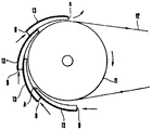
제 1도는 직물을 연속처리하는 종래의 실린더건조기 전체설명도.1 is a schematic diagram of a conventional cylinder dryer for continuously processing a fabric.
제 2도는 본 발명에 의한 실린더건조기의 실시예를 도시한 요부측면도.Figure 2 is a side view of the main portion showing an embodiment of a cylinder dryer according to the present invention.
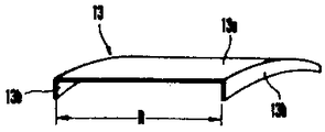
제 3도는 제 2도 부재의 사시도.3 is a perspective view of the second FIG. Member.
제 4도는 본 발명의 다른 실시예를 도시한 요부측면도.Figure 4 is a side view of the main portion showing another embodiment of the present invention.
제 5도는 제 4도 부재의 사시도.5 is a perspective view of the FIG. 4 member.
*도면의 주요부분에 대한 부호의 설명* Explanation of symbols for main parts of the drawings
1 : 세정조 4 : 건조실1: washing tank 4: drying chamber
11 : 열실린더 12 : 함수직물11: heat cylinder 12: function fabric
13 : 반사판 13a : 곡면부13 reflector 13a: curved portion
13b : 측벽부 213 : 반사판13b: side wall 213: reflector
213a : 곡면부 213 b : 선단휨부213a: curved portion 213b: tip bent portion
213c : 후단휨부 214 : 기체가이드부재213c
본 발명은 직물을 위해 실린더건조기에서의 건조효율을 높이도록된 실린더건조기에 관한 것이다.The present invention relates to a cylinder dryer adapted to increase drying efficiency in a cylinder dryer for fabric.
공업적으로 생산하는 긴 직물은 예를 들면 예비처리, 염색처리, 머어서리화(mercerization: 실켓(silket)가공)가공, 축융(縮絨 :fulling)가공 등의 처리가공 후에는, 그 직물을 세정하는 세정처리가공이 필요하며, 더우기 이것들의 세정처리 후에는, 그것을 연속적으로 건조하는 건조공정이 필요하다.Industrially produced long fabrics are washed, for example, after pretreatment, dyeing, mercerization, fulling, etc. The cleaning process is required, and furthermore, after these cleaning processes, a drying step of continuously drying it is required.
이 연속적 건조수단의 종래예로서는, 예를 들면 제 1도에 도시된 바와 같이, 다수의 세정조(1)내를 연속적으로 통과시켜서 소망하는 세정을 완료한 직물(2)을 다수개의 열실린더(3)가 배설되어 있는 실린더건조실(4)내를 통과하고, 그러한 다수개의 열실린더(3)에 건조시켜야 할 직물(2)을 차례로 접촉시키면서 이송함으로서, 그 건조실(4)로부터 도출된 직물의 건조가 완료되는 실린더건조기가 있다. 그러나, 이러한 종래의 열실린더건조기에 있어서는, 젖은 직물을, 예를 들면 125~130℃로 가열시킨 열실린더(3)에 접촉시켜서, 직물에 부착되어 있는 수분을 기화시키는 것에 있어서, 그 직물주변부에 발생하는 기화수분의 강제제거작용이 없기 때문에, 열실린더(3)의 가열에 의해, 직물로부터 떨어진 직후의 수분이 있는 직물표면에 발생한 증기층의 재부착 등이 있어서, 건조가 완료될때까지 장시간을 필요하고, 더우기 열실린더 원주면에서의 방열에 의해 직물로의 가열력이 불충분한 경우에는, 다수개의 열실린더를 배치하지 않으면 안되고, 건조실의 막대화 혹은 열에너지 소비량의 다량화 등으로 되고, 설비비, 건조비용, 건조효율 등의 점에서 문제가 있었다.As a conventional example of this continuous drying means, as shown in FIG. 1, for example, as shown in FIG. 1, a plurality of thermal cylinders 3 are formed by continuously passing through the plurality of cleaning tanks 1 and completing the desired cleaning. ) Passes through the inside of the cylinder drying chamber 4 in which the fabric is disposed, and the fabrics 2 to be dried are brought into contact with each other in order to dry the fabrics derived from the drying chamber 4. There is a cylinder dryer completed. However, in such a conventional heat cylinder dryer, the wet fabric is brought into contact with the heat cylinder 3 heated at 125 to 130 ° C., for example, to vaporize moisture adhering to the fabric. Since there is no forced removal action of vaporized water generated, there is a re-attachment of the vapor layer generated on the surface of the moist fabric immediately after it is removed from the fabric due to the heating of the heat cylinder 3, and a long time until the drying is completed. In addition, in the case where heating power to the fabric is insufficient due to heat dissipation on the circumferential surface of the heat cylinder, a plurality of heat cylinders must be arranged, and the drying chamber is increased or the heat energy consumption is increased. There was a problem in terms of drying cost and drying efficiency.
본 발명은, 이러한 종래의 실린더건조기에 대한 문제점을 해소하기 위한 것이며, 함수직물이 열실린더와의 접촉에 의해서 발생하는 기화수분을 그 직물에서 효율적으로 분리제거시키는 것 또는 열실린더의 방열을 억제하는 것에 의해, 건조효율을 향상시키고 또 에너지절약에도 이익이되는 실린더건조기를 제공하는 것을 목적으로 하는 것이다.The present invention is to solve the problems of the conventional cylinder dryer, and to effectively remove and remove the vaporized water generated by the water-containing fabric in contact with the heat cylinder from the fabric or to suppress the heat radiation of the heat cylinder It is an object of the present invention to provide a cylinder dryer that improves drying efficiency and is also advantageous in energy saving.
이상의 목적을 달성하기 위한 본 발명 실린더건조기는 다음과 같은 구성을 특징으로 하는 것이다.The cylinder dryer of the present invention for achieving the above object is characterized by the following configuration.
(1) 열실린더의 일부를 피건조직물 당접면에 대향시켜서, 각 반사판의 선단부와 열실린더와의 간격이, 그 후단부와 열실린더와의 간격보다도 적도록하여 열실린더 위에 다수개의 반사판을 격설하고, 더구나 서로 인접하는 한쪽의 반사판 선단부위에 다른쪽의 반사판 후단부가 격설되도록 배설시킨 것을 특징으로 하는 실린더건조기이다.(1) A plurality of reflecting plates are arranged on the thermal cylinders so that a part of the thermal cylinders faces the abutment surface of the workpiece, so that the distance between the tip of each reflecting plate and the thermal cylinder is smaller than the distance between the rear end and the thermal cylinder. Further, the cylinder dryer is characterized in that the rear end portion of the other reflecting plate is disposed so as to be disposed on the front end portions of one reflecting plate adjacent to each other.
(2) 열실린더의 일부를 피건조직물 당접면에 대향시켜서, 각 반사판의 선단부와 열실린더와의 간격이, 그후단부와 열실린더와의 간격보다도 적도록하여 열실린더 위에 다수개의 반사판을 격설함과 동시에, 서로 인접하는 쌍방의 반사판 상호간에 흡배기용의 간극을 설치한 것을 특징으로 하는 실린더건조기이다.(2) A part of the heat cylinder is opposed to the contact surface of the object to be dried, and a plurality of reflecting plates are arranged on the heat cylinder so that the distance between the tip of each reflecting plate and the heat cylinder is smaller than the distance between the rear end and the heat cylinder. At the same time, the cylinder dryer is characterized in that a gap for intake and exhaust air is provided between two reflection plates adjacent to each other.
본 발명의 다른 목적과 장점을 첨부된 도면과 연관하여 바람직한 실시예의 설명으로 명백해질 것이다.Other objects and advantages of the present invention will become apparent from the description of the preferred embodiments in conjunction with the accompanying drawings.
이하, 본 발명의 바람직한 실시예를 제2도~제5도에 도시한 실시예에 기초하여 상세히 설명한다.Hereinafter, preferred embodiments of the present invention will be described in detail based on the embodiments shown in FIGS.
[실시예 1]Example 1
제2도 및 제3도는 본 발명의 제1실시예를 도시한다. 도면중(11)은 열실린더이며, 이 열실린더(11)는 종래예에 도시된 것과 같은 모양으로, 건조실(4)내에 있어서 다수개가 배설되고, 이러한 실린더(11)에 건조시킬 함수직물(12)이 접촉가이드되어 이송되는 것에 의해서, 함수직물(12)은, 열실린더(11)의 직물접촉면에 대응하여 복수의 반사판(13)을 열실린더와 격설한 상태이고, 더구나 그 열실린더(11)의 회전방향으로 배설하여 있지만, 이러한 반사판(13)의 형상은, 제3도에 도시된 바와 같이, 열실린더(11)의 원주면 곡률과 대략 같은 곡률의 곡면부(13a)와, 그 곡면부(13a)의 양측변 모서리에서 형성된 측벽부(13b)로 되어 있고, 이러한 쌍방의 측벽부(13b) 상호간격 R은, 열실린더(11)의 축방향 길이보다도 약간 크게되도록 설정되어 있다. 또 이러한 반사판(13)의 배치는 제1도에 도시된 바와 같이, 그 선단부 A가 열실린더(11)의 회전방향으로 향하도록 위치시킴과 동시에, 이 반사판(13)의 선단부 A와 열실린더(11)와의 간극이, 그 후단부 B 와 열실린더(11)와의 간극보다 좁게하고, 더우기, 서로 인접하는 한쪽의 반사판(13) 선단부 A위에 다른쪽의 반사판(13) 후단부 B가 격설된 상태로 위치되도록 하여, 복수(본 실시예에서는 4개)의 반사판(13)을 열실린더(11)의 직물당접면위에 배설시킨 것이다.2 and 3 show a first embodiment of the present invention. In the figure, 11 is a heat cylinder, and the heat cylinder 11 has the same shape as that shown in the conventional example, and a plurality of heat cylinders 11 are disposed in the drying chamber 4, and the water-containing fabric 12 to be dried in the cylinder 11 is shown. ) Is guided and conveyed so that the water-repellent fabric 12 is in a state in which a plurality of reflecting
이 실시예에 있어서, 열실린더(11)의 일부를 피건조직물과의 당접면상에 반사판(13)과 접근상태로 배설시킨 것이므로, 열실린더(11)의 원주면에서 직물(12)을 통과하여 방열시키도록 한 열이 반사판(13)에 반사되어서, 다시 직물(12)의 표면에 조사부여되어 열을 유효하게 이용하고, 열에너지의 절약화와, 건조속도가 빠른 효과가 있다. 또 각 반사판의 선단부 A와 열실린더(11)와의 간격이 그 후단부 B와 열실린더(11)과의 간격보다도 적도록 다수개의 반사판(13)을 격설하고, 더구나 서로 인접하는 한쪽의 반사판(13) 선단부 A위에 다른쪽의 반사판 후단부 B가 격설되도록 배치시킨 것이므로, 이러한 반사판(13)과 열실린더(11)와의 사이에 있어서는, 열실린더(11)의 회전에 따른 기류가 생기고 이 기류에 의해서 직물(12)에서 발생한 증기열(기화열)이, 최선단 반사판(13)의 선단부 A에서 유효하게 방출됨과 동시에, 각 반사판(13)의 선단부 A와, 후단부 B와의 사이에 설치되어 있는 간극에서는 습도가 적은 외기가 흡입공급되기 때문에, 다습공기와 저습공기와의 치환작용이 크므로서 이것에 의해서도 극히 효과적인 직물건조가 계속적으로 행할 수 있는 것이다.In this embodiment, a part of the heat cylinder 11 is disposed on the contact surface with the dry matter in the state of approach with the reflecting
상기의 실시예에 있어서는, 열실린더 원주면에서 피건조직물을 통과하여 방열하도록한 열이 반사판에 반사되어서, 다시 직물의 표면에 조사부여되어서 열을 유효하게 이용하고 또 이러한 반사판과, 열실린더와의 사이에 있어서는, 열실린더의 회전에 따른 기류가 생기고 이 기류에 의해서 직물(12)에서 발생한 증기열(기화열)이, 최선단 반사판의 선단부에서 유효하게 방출됨과 동시에, 각 반사판의 선단부와 후단부와의 사이에 설치되어 있는 간극에서는, 습도가 적은 외기가 흡입공급되기 때문에 다습공기와 저습공기와의 치환작용이 크므로서 열에너지를 절약하면서 단시간에 효과적인 직물건조가 연속적으로 행하여지는 이점이 있다.In the above embodiment, the heat that radiates heat from the circumferential surface of the heat cylinder through the dry matter is reflected on the reflecting plate, and is then irradiated to the surface of the fabric to effectively utilize the heat, and the reflecting plate, the heat cylinder and In between, the airflow caused by the rotation of the heat cylinder is generated, and the heat of vaporization (heat of vaporization) generated in the fabric 12 by this airflow is effectively released from the front end of the uppermost reflector, and at the front and rear ends of each reflector. In the gap provided between and, the low-humidity air is sucked in and supplied, so that the substitution effect between the humid air and the low-humidity air is large, and thus the fabric drying is effectively performed in a short time while saving thermal energy.
[실시예 2]Example 2
제 4도 및 제5도는 본 발명의 제 2실시예를 도시한다. 도면중(211)은 열실린더이며, 이 열실린더(211)는 종래예에 도시된 것과 같은 모양으로 건조실(4)내에 있어서 다수개가 배설되고, 이러한 실린더(211)에 건조시킬 함수직물(211)이 접촉가이드되어 이송되는 것에 의해서 함수직물(211)은, 열실린더(211)의 가열력을 수용하여 다음에 건조시키는 것이다. 이 실시예에 있어서는, 열실린더(211)의 직물접촉면에 대응하여 복수의 반사판(213)을 열실린더면과 격설한 상태이고, 더구나 그 열실린더(211)의 회전방향에 배설되어 있지만, 이러한 반사판(213)의 형상은 제5도에 도시된 바와 같이, 열실린더(211)의 원주면 곡률과 대략 같은 곡률의 곡면부(213a)와, 그 곡면부 (213a)의 전후 양단부에 있어서, 그 곡면부(213a)의 곡면과 역방향의 곡면에 형성된 휨부(213b)(213c)와 , 곡면부(213a)의 양측변 모서리에 있어서 형성된 측벽부(213d)로 되어있고, 이러한 쌍방의 측벽부 (213d)의 상호간격 R은 열실린더(211)의 축방향 길이보다도 약간 크도록 설정되어 있다. 또, 이러한 반사판(213)의 배치는 제4도에 도시된 바와 같이, 그 선단휨부(213b)가 열실린더(211)의 회전방향으로 향하도록 위치시킴과 동시에, 선단휨부(213b)와 열실린더(211)와의 간극이, 그 후단휨부(211c)와 열실린더(11)와의 간극보다 좁게 배치하고, 또, 한쪽 반사판(213)의 후단과 다른쪽 반사판의 선단과의 사이는 적절한 간격을 설치함과 동시에, 이 간격부에 기체가이드부재(214)를 위치시켜서, 열실린더(211)와 반사판(213)사이의 기체의 배출 또는 그 사이에 외기를 흡입하는 것이 원활하도록 되어있다.4 and 5 show a second embodiment of the present invention. In the figure, 211 is a heat cylinder, and a plurality of the
이 실시예에 있어서, 열실린더(211)의 일부를 피건조직물과의 당접면상에, 복수개의 반사판(213)을 그 열실린더(211)의 원주방향으로 배설시킨 것이므로, 열실린더(211)의 가열에 의해 그 열실린더(211)의 원주면에서 직물(212)을 통과하여 방열시키도록한 열이, 반사판(213)에 반사되어서, 다시 직물(212)의 표면에 조사부여되어 열을 유효하게 이용하고, 열에너지의 절약화와, 건조속도가 빠른 효과가 있다. 또 다수개의 반사판(213)은 인접하여 설치된 서로의 사이가, 격설된 상태이므로, 열실린더(211)와 반사판(213)과의 사이의 증기열(기화수분)은, 열실린더(211)의 회전에 따른 각 반사판(213)의 선단부(213b)에서 유효하게 방출됨과 동시에, 각 반사판(213)의 후단부(213c)에서는, 비교적 습도가 낮은 외기가 반사판(213)과 열실린더(211)와의 사이로 흡입되어, 다습공기와 저습공기와의 치환작용이 크므로서 극히 효과적인 직물건조가 연속적으로 행하여지는 것이다.In this embodiment, since a part of the
상기의 실시예에 있어서는, 제1실시예와 같은 효과가 얻어지지만, 각 반사판의 후단부에서는 반사판과 열실린더와의 간극을 향하여 습도가 낮은 외기가 흡입공급되므로, 다습공기와 저습공기와의 치환작용이 크므로서 열에너지 절약면에서 단시간에 효과적인 직물건조가 연속적으로 행하여지는 이점이 있다.In the above embodiment, the same effect as in the first embodiment can be obtained. However, at the rear end of each reflecting plate, the low humidity air is sucked in and supplied to the gap between the reflecting plate and the heat cylinder, thereby replacing the humid air with the low humidity air. Since the action is large, there is an advantage that the fabric drying is performed continuously in a short time in terms of thermal energy saving.
본 발명이 상기의 실시예로 제한되는 것은 아니고, 첨부한 청구범위를 벗어나지 않는 범위내에서 여러 가지 수정을 행할 수 있음은 물론이다.It is a matter of course that the present invention is not limited to the above embodiments, and various modifications can be made without departing from the scope of the appended claims.
Claims (2)
Applications Claiming Priority (3)
| Application Number | Priority Date | Filing Date | Title |
|---|---|---|---|
| JP61-105461 | 1986-07-09 | ||
| JP1986105461U JPH0517589Y2 (en) | 1986-07-09 | 1986-07-09 | |
| JP105462 | 1986-07-09 |
Publications (2)
| Publication Number | Publication Date |
|---|---|
| KR880001874A KR880001874A (en) | 1988-04-27 |
| KR910001700B1 true KR910001700B1 (en) | 1991-03-18 |
Family
ID=30979915
Family Applications (1)
| Application Number | Title | Priority Date | Filing Date |
|---|---|---|---|
| KR1019870007378A KR910001700B1 (en) | 1986-07-09 | 1987-07-09 | Cylinder drying machine |
Country Status (2)
| Country | Link |
|---|---|
| JP (1) | JPH0517589Y2 (en) |
| KR (1) | KR910001700B1 (en) |
Family Cites Families (2)
| Publication number | Priority date | Publication date | Assignee | Title |
|---|---|---|---|---|
| JPS4977244A (en) * | 1972-11-28 | 1974-07-25 | ||
| DE2540851C3 (en) * | 1975-09-13 | 1978-08-10 | Hoechst Ag, 6000 Frankfurt | Process and additional device for cylinder drying machines for uniform drying of textile materials |
-
1986
- 1986-07-09 JP JP1986105461U patent/JPH0517589Y2/ja not_active Expired - Lifetime
-
1987
- 1987-07-09 KR KR1019870007378A patent/KR910001700B1/en not_active IP Right Cessation
Also Published As
| Publication number | Publication date |
|---|---|
| JPS6314989U (en) | 1988-01-30 |
| JPH0517589Y2 (en) | 1993-05-11 |
| KR880001874A (en) | 1988-04-27 |
Similar Documents
| Publication | Publication Date | Title |
|---|---|---|
| JPS625074A (en) | Infrared drier | |
| WO2013151214A1 (en) | Dryer | |
| SE8603556L (en) | DIRECTLY CYLINDER DRYER | |
| KR20040046459A (en) | flow route for cooling in condenser for condensing type clothes drier | |
| KR910001700B1 (en) | Cylinder drying machine | |
| JPH0517590Y2 (en) | ||
| CN215593496U (en) | Gas hood with dehumidification function | |
| US4750275A (en) | Cylinder drying machine | |
| CN211713460U (en) | Drum-type microwave heating dryer | |
| KR100459143B1 (en) | flow route for deflation cooling fan in condenser for condesing type clothes drier | |
| CN221142168U (en) | Multistage formula fabric stoving setting device | |
| KR980002405A (en) | Drum washing machine drying device | |
| SU1231352A1 (en) | Continuous-belt drier | |
| CN220564923U (en) | Heating assembly, drying module and clothes treatment device | |
| JPH0274660A (en) | Pad dryer | |
| CN211527019U (en) | Efficient automatic pre-drying device | |
| CN219347181U (en) | Efficient dryer | |
| CN216998894U (en) | Feeding mechanism of setting machine | |
| KR950005347Y1 (en) | High frequency clothing dryer | |
| CN214300901U (en) | Wind path structure of air outlet module and clothes drying device | |
| KR960010253Y1 (en) | Clothing dryer | |
| JPS645518A (en) | Tableware washing machine | |
| JPH018944Y2 (en) | ||
| KR19980031940U (en) | Dry Washing Machine Using Radiant Heat | |
| SU1514275A1 (en) | Apparatus for heating and blowing the upper zone of storage for vegetative produce |
Legal Events
| Date | Code | Title | Description |
|---|---|---|---|
| A201 | Request for examination | ||
| G160 | Decision to publish patent application | ||
| E701 | Decision to grant or registration of patent right | ||
| GRNT | Written decision to grant | ||
| LAPS | Lapse due to unpaid annual fee |