KR900008928B1 - Air cleaner - Google Patents
Air cleaner Download PDFInfo
- Publication number
- KR900008928B1 KR900008928B1 KR1019870010049A KR870010049A KR900008928B1 KR 900008928 B1 KR900008928 B1 KR 900008928B1 KR 1019870010049 A KR1019870010049 A KR 1019870010049A KR 870010049 A KR870010049 A KR 870010049A KR 900008928 B1 KR900008928 B1 KR 900008928B1
- Authority
- KR
- South Korea
- Prior art keywords
- sensor
- ultraviolet
- output
- time
- ultraviolet sensor
- Prior art date
Links
Images


Classifications
-
- F—MECHANICAL ENGINEERING; LIGHTING; HEATING; WEAPONS; BLASTING
- F24—HEATING; RANGES; VENTILATING
- F24F—AIR-CONDITIONING; AIR-HUMIDIFICATION; VENTILATION; USE OF AIR CURRENTS FOR SCREENING
- F24F8/00—Treatment, e.g. purification, of air supplied to human living or working spaces otherwise than by heating, cooling, humidifying or drying
- F24F8/10—Treatment, e.g. purification, of air supplied to human living or working spaces otherwise than by heating, cooling, humidifying or drying by separation, e.g. by filtering
- F24F8/192—Treatment, e.g. purification, of air supplied to human living or working spaces otherwise than by heating, cooling, humidifying or drying by separation, e.g. by filtering by electrical means, e.g. by applying electrostatic fields or high voltages
-
- F—MECHANICAL ENGINEERING; LIGHTING; HEATING; WEAPONS; BLASTING
- F24—HEATING; RANGES; VENTILATING
- F24F—AIR-CONDITIONING; AIR-HUMIDIFICATION; VENTILATION; USE OF AIR CURRENTS FOR SCREENING
- F24F8/00—Treatment, e.g. purification, of air supplied to human living or working spaces otherwise than by heating, cooling, humidifying or drying
- F24F8/10—Treatment, e.g. purification, of air supplied to human living or working spaces otherwise than by heating, cooling, humidifying or drying by separation, e.g. by filtering
- F24F8/108—Treatment, e.g. purification, of air supplied to human living or working spaces otherwise than by heating, cooling, humidifying or drying by separation, e.g. by filtering using dry filter elements
-
- B—PERFORMING OPERATIONS; TRANSPORTING
- B03—SEPARATION OF SOLID MATERIALS USING LIQUIDS OR USING PNEUMATIC TABLES OR JIGS; MAGNETIC OR ELECTROSTATIC SEPARATION OF SOLID MATERIALS FROM SOLID MATERIALS OR FLUIDS; SEPARATION BY HIGH-VOLTAGE ELECTRIC FIELDS
- B03C—MAGNETIC OR ELECTROSTATIC SEPARATION OF SOLID MATERIALS FROM SOLID MATERIALS OR FLUIDS; SEPARATION BY HIGH-VOLTAGE ELECTRIC FIELDS
- B03C3/00—Separating dispersed particles from gases or vapour, e.g. air, by electrostatic effect
- B03C3/02—Plant or installations having external electricity supply
-
- F—MECHANICAL ENGINEERING; LIGHTING; HEATING; WEAPONS; BLASTING
- F24—HEATING; RANGES; VENTILATING
- F24F—AIR-CONDITIONING; AIR-HUMIDIFICATION; VENTILATION; USE OF AIR CURRENTS FOR SCREENING
- F24F8/00—Treatment, e.g. purification, of air supplied to human living or working spaces otherwise than by heating, cooling, humidifying or drying
- F24F8/95—Treatment, e.g. purification, of air supplied to human living or working spaces otherwise than by heating, cooling, humidifying or drying specially adapted for specific purposes
- F24F8/97—Treatment, e.g. purification, of air supplied to human living or working spaces otherwise than by heating, cooling, humidifying or drying specially adapted for specific purposes for removing tobacco smoke
-
- F—MECHANICAL ENGINEERING; LIGHTING; HEATING; WEAPONS; BLASTING
- F24—HEATING; RANGES; VENTILATING
- F24F—AIR-CONDITIONING; AIR-HUMIDIFICATION; VENTILATION; USE OF AIR CURRENTS FOR SCREENING
- F24F2221/00—Details or features not otherwise provided for
- F24F2221/12—Details or features not otherwise provided for transportable
-
- Y—GENERAL TAGGING OF NEW TECHNOLOGICAL DEVELOPMENTS; GENERAL TAGGING OF CROSS-SECTIONAL TECHNOLOGIES SPANNING OVER SEVERAL SECTIONS OF THE IPC; TECHNICAL SUBJECTS COVERED BY FORMER USPC CROSS-REFERENCE ART COLLECTIONS [XRACs] AND DIGESTS
- Y02—TECHNOLOGIES OR APPLICATIONS FOR MITIGATION OR ADAPTATION AGAINST CLIMATE CHANGE
- Y02A—TECHNOLOGIES FOR ADAPTATION TO CLIMATE CHANGE
- Y02A50/00—TECHNOLOGIES FOR ADAPTATION TO CLIMATE CHANGE in human health protection, e.g. against extreme weather
- Y02A50/20—Air quality improvement or preservation, e.g. vehicle emission control or emission reduction by using catalytic converters
-
- Y—GENERAL TAGGING OF NEW TECHNOLOGICAL DEVELOPMENTS; GENERAL TAGGING OF CROSS-SECTIONAL TECHNOLOGIES SPANNING OVER SEVERAL SECTIONS OF THE IPC; TECHNICAL SUBJECTS COVERED BY FORMER USPC CROSS-REFERENCE ART COLLECTIONS [XRACs] AND DIGESTS
- Y10—TECHNICAL SUBJECTS COVERED BY FORMER USPC
- Y10S—TECHNICAL SUBJECTS COVERED BY FORMER USPC CROSS-REFERENCE ART COLLECTIONS [XRACs] AND DIGESTS
- Y10S55/00—Gas separation
- Y10S55/34—Indicator and controllers
Abstract
내용 없음.No content.
Description
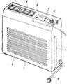
제1도는 본 발명의 일실시예의 공기청정기를 도시한 외관사시도.1 is an external perspective view showing an air cleaner of an embodiment of the present invention.
제2도는 동회로 블록도.2 is a block diagram of the same circuit.
제3a도, 제3b도, 제3c도는 동 자외선센서의 출력관계의 설명도.3A, 3B, and 3C are explanatory views of the output relationship of the same ultraviolet sensor.
제4도는 가스 및 자외선센서의 출력등의 타이밍을 도시한 도면.4 is a diagram showing timing of outputs of a gas and an ultraviolet sensor.
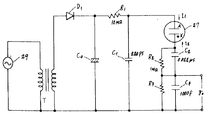
제5도는 자외선센서의 검지회로의 구체적인 회로를 도시한 도면.5 is a diagram showing a specific circuit of the detection circuit of the ultraviolet sensor.
제6도는 전원투입시에 있어서의 가스센서의 타이밍을 도시한 도면.Fig. 6 is a diagram showing the timing of the gas sensor when the power is turned on.
제7도는 종래의 공기청정기를 도시한 외관사시도.7 is a perspective view showing a conventional air cleaner.
제8도는 동 회로 블록도.8 is the same circuit block diagram.
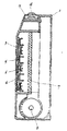
제9도는 동 측단면도.9 is the same side cross-sectional view.
* 도면의 주요부분에 대한 부호의 설명* Explanation of symbols for main parts of the drawings
20 : 흡기가 21 : 배기구20: intake air 21: exhaust port
22 : 필터 23 : 원격제어부22: filter 23: remote control unit
24a : 풍량설정스위치 24c : 절환수단24a: air flow setting switch 24c: switching means
26 : 가스센서 27 : 자외선센서26
29 : 전원 30 : 제어회로29: power supply 30: control circuit
31 : 조작회로 33, 34 : 검지회로31: operation circuit 33, 34: detection circuit
35 : 담배 36 : 라이터35: cigarette 36: lighter
37 : 타이머수단 38 : 계수수단37: timer means 38: counting means
39 : 리세트수단 40 : 표지수단39: reset means 40: cover means
본 발명은, 센서에 의하여 실내의 공기의 오염을 검지하여, 자동운전을 행하는 기능을 가진 공기청정기에 관한 것이다.The present invention relates to an air cleaner having a function of detecting contamination of air in a room by a sensor and performing automatic operation.
종래, 이런종류의 공기청정기에 대해서, 일반적인 구성을 도면을 참조하면서 이하에 설명한다.Conventionally, a general structure of this kind of air cleaner will be described below with reference to the drawings.
제7도, 제8도 및 제9도에 있어서, 본체(1)에는 전동송풍기(2)를 내장하고, 앞면의 흡기구(3)로부터 흡입한 공기는 전치필터(4)를 통과하여, 대향전극(5)과 방전선(6)에 의하여 이온화되고, 필터(7)로 먼지가 흡착된 후, 배기구(8)로부터 배출된다. 본체(1)의 상부에 착탈자재하게 장착된 원격제어케이스(9)에는 조작용 스위치(10)와 표시부(11)를 착설하고, 또한 실내의 공기가 오염된 것을 검출하기 위한 가스센서(12)를 내장하고 있다. 그리하여 조작스위치(10)에 의해 자동모우드로 운전이 설정되면, 가스센서(12)의 출력을 검출회로(13)가 입력하고, 이것을 전원(14)과 조작회로(15)에 접속된 제어회로(16)가 판단하여, 전동송풍기(2) 및 대향전극(5)과 방전선(6)간에 전압을 공급하는 전원(14) 및 표시회로(17)를 제어한다. 즉, 실내의 오염을 검출하였을 경우에는 온하고, 청정하게 되었을 경우에 오프하는 자동운전을 행하는 것이다. 또한, (18)은 전원코오드이다.7, 8 and 9, the main body 1 has a built-in electric blower 2, and the air sucked in from the intake port 3 on the front side passes through the prefilter 4, and the counter electrode It is ionized by 5 and the discharge line 6, and dust is adsorbed by the filter 7, and is discharged from the
이와같은, 종래의 자동운전기능 부착의 공기청정기에서는, 센서로서 가스센서(12)을 이용하고 있었기 때문에 실제적인 사용에 불편이 있었다. 즉, 공기청정기의 주된 사용 용도인 끽연시의 공기정화의 경우등에는, 담배(煙草)에 착화하여 끽연을 개시한 후, 담배로부터 발생하는 연기입자와 가스성분이 방안에 확산하여, 가스센서(12)에 도달해서 비로소 기기가 동작을 개시하기 때문에 물리적으로 아무리하여도 대기시간이 필요하다고 하는 문제가 있었다. 또, 일반적인 가스센서는, 그 구성중에 히이터부를 가지고 있는 것이 많아, 전원을 투입후, 히이터부의 온도가 안정되고, 안정된 출력을 얻어질때까지 사이에, 수분의 대기시간도 필요하고, 그 동안에는 가스센서 출력에 의한 자동운전이 안된다고 하는 문제가 있었다.In such a conventional air purifier with an automatic driving function, since the gas sensor 12 is used as a sensor, practical use is inconvenient. That is, in the case of air purification during smoking, which is the main use of the air cleaner, after ignition by starting with smoking, the smoke particles and gaseous components generated from the cigarette diffuse into the room, and the gas sensor ( Since the device starts to operate after reaching 12), there is a problem that no matter how long the physical time is required. In addition, a common gas sensor has a heater portion in its configuration, and a waiting time of a few minutes is required between the time of turning on the power supply until the temperature of the heater portion is stabilized and a stable output is obtained. There was a problem that automatic operation by output was not possible.
본 발명은 이와같은 문제점을 해결하는 것으로서, 속응성을 가진 센서를 이용한 사용성이 높은 공기청정기를 제공하는 것을 목적으로 하고 있다.The present invention has been made to solve such a problem, and an object of the present invention is to provide a highly usable air cleaner using a sensor having quick response.
상세하게, 본 발명의 목적은 담배등에의 착화를 검출하는 자외선센서와, 실내의 공기오염의 오염정도를 검출하는 가스센서와, 공기중의 오염을 흡착하는 필터와, 상기 자외선센서와 가스센서의 출력으로부터 기기의 운전방법을 결정하는 제어회로를 지니는 공기청정기를 제공하는데 있다.In detail, an object of the present invention is to provide an ultraviolet sensor for detecting ignition in cigarettes, a gas sensor for detecting a pollution level of air pollution in a room, a filter for absorbing air pollution, and It is to provide an air cleaner having a control circuit that determines the operation method of the equipment from the output.
본 발명은, 상기의 구성에 의해, 끽연을 개시하는 시점에서 점화용 라이터, 성냥 등의 불꽃을 자외선센서에 의해서 즉시로 검출하여, 자동운전을 개시할 수 있는 것이며, 또한 자외선센서의 출력을 일정한 시간폭 이상에 걸쳐서 소정의 수 이상의 펄스가 관측되는지 여부의 판단에 의해서, 오동작신호인지 상기 점화용 불꽃으로부터의 신호인지를 식별하기 때문에, 즉응성의 센서를 오동작을 방지하여 사용할 수 있는 것이다.In accordance with the above-described configuration, the present invention can immediately detect sparks such as a ignition lighter and a match by using an ultraviolet sensor at the time of starting smoking, and start automatic operation. By discriminating whether or not a predetermined number or more of pulses are observed over the time width, it is identified whether the signal is a malfunction signal or the signal from the spark for ignition, and thus an immediate sensor can be prevented and used.
이하, 본 발명의 일실시예에 대해서 도면을 참조하면서 설명한다. 또한, 공기청정기 자체의 기본구성은 제7도, 제9도에 도시한 종래의 것과 다르지 않으므로, 상위점을 중심으로 설명한다.Hereinafter, an embodiment of the present invention will be described with reference to the drawings. In addition, since the basic structure of the air cleaner itself does not differ from the conventional one shown in FIG. 7, FIG. 9, it demonstrates centering around difference.
제1도에 있어서, 본체(19)의 앞면에 형성한 흡기구(20)로부터 흡입한 공기는 상면의 배기구(21)로부터 배출되고, 그 유로중에 착설된 필터(22)에 의하여, 흡입한 공기 속의 먼지를 흡착하는 것이다.In FIG. 1, the air sucked in from the intake port 20 formed on the front surface of the main body 19 is discharged from the
기류를 발생시키는 전동송풍기(32)는 본체(19)에 내장되고, 필터(22)와 배기구(21)의 사이의 유로중에 배치되어 있다. 이 전동송풍기(32)는 원격제어부(23)에 착설한 풍량설정스위치(24a)의 조작에 의해서도 그 풍량을 강, 중, 약으로 구동하여 각각의 풍량에 해당하는 표시등(25a : 강), (25b : 중), (25c : 약)이 점등한다. 또 원격제어부(23)에는, 자동운전의 조작위치에 풍량설정스위치(24a)를 설정하면 표시등(25d)이 점등하여 가스센서(26) 및 자외선센서(27)로부터의 출력에 대응한 자동운전을 행하는 제어회로도 내장하고 있다. 자외선센서(27) 및 필터의 교환표시수단(40), 필터교환후에 계수수단(38)의 내용을 리세트하는 리세트수단(39)은 본체(19)의 앞면에 배설되어 있다. 또, 필터의 사용시간을 타이머수단으로 정해진 시간마다 계수를 행하는 계수수단 및 그 설정을 절환하는 절환수단(24c)도 원격제어부(23)에 내장하고 있다. 타이머설정스위치(24b)에 의해서 타이머를 1시간, 2시간, 6시간으로 설정할 수 있어(해당하는 표시등 25e(1시간), 25f(2시간), 25g(6시간)의 어느 하나가 점등), 전동송풍기(32)를 타이머 운전할 수 있다.The electric blower 32 which generates airflow is built in the main body 19, and is arrange | positioned in the flow path between the filter 22 and the
제2도에 의해 회로계통을 설명하면, 전원(29)에 접속된 제어회로(30)는, 상기 풍량설정스위치(24a), 타이머설정스위치(24b)를 포함하는 조작회로(31)로부터의 신호를 얻어서, 상기 전동송풍기(32)를 구동하고, 자동운전으로 설정되어 있는 경우에는, 상기 가스센서(26)로부터의 출력을 검지회로(33)를 거쳐서 제어회로(30)에 입력하고, 마찬가지로 자외선센서(27)로부터의 출력은 검지회로(34)를 거쳐서 제어회로(30)는 전동송풍기를 자동운전한다. 여기서, 가스센서(26)는 주로 끽연시의 담배(35)의 연기나 가스성분등을 검출하고, 자외선센서(27)는 담배(35)를 착화시키기 위한 라이터(36)의 불꽃을 검지하는 것이다.Referring to FIG. 2, the control circuit 30 connected to the
그러나, 여기에서 사용한 자외선센서(27)는 라이터등의 불꽃을 검출가능할 정도로 감도가 높은 것으로 되면, 자외선센서(27)자신의 오동작(예를 들면 자기방전이나 형광등의 빛, 우주선등)이 문제가 되기 때문에, 검지회로(34)와 제어회로(30)에 있어서, 오동작을 방지하는 일이 필요하게 된다. 제3a도에서는 오동작의 경우의 자외선센서 출력을 도시하며, 짧은시간 t1의 사이에 수개의 펄스가 발생한다. 제3b도에서는 라이터등의 불꽃을 검출하였을 경우의 출력으로서, 이 경우는 상기 t1보다 긴 시간 t2의 간격을 가지고 수개의 펄스가 발생하는 경우가 많다. 그리하여 본 발명에서는 제3c도에 도시한 바와같이, 1회째의 펄스가 발생한 시점(t0)에서부터 대기시간(t3)의 사이는 신호를 무시하고, 그 후의 검출시간(t4)의 사이에 몇회의 펄스(계측수)가 발생하는지를 검출하여(실험에 의해, 2회 혹은 3회가 바람직하다). 자외선센서(27)의 출력에 의한 자동운전을 개시하는 것이다. 여기서 (t3)는 (t1)보다 길고, (t4)는 (t3)보다 긴 시간으로 하고, (t3)는 약 10m sec(t4)는 약 2sec정도가 적당하다고 생각된다.However, when the
이상의 구성에 있어서 동작을 설명하면, 풍량설정스위치(24a)을 조작하여 자동운전으로 설정해두고, 사용자가 끽연을 개시하기 위하여 라이터(36)등을 정화하면, 즉시로 자외선센서(27)가 그 불꽃을 검출하고, 검지회로(34)를 개재해서 제어회로(30)에 신호를 전달하고, 전동송풍기(32)가 동작을 개시한다. 이에 의하여, 흡기구(20)로부터의 실내의 공기가 유입하고, 배기구(21)로부터 유출하게 되어, 담배(36)의 연기 및 가스성분의 확산속도가 빨라지게 된다.The operation in the above configuration will be explained. When the air
여기서 자외선센서(27)와 가스센서(26)에 의한 동작상태를 제4도에 도시한다. 가스센서(26)의 출력은, 제4a도와 같이 시간과 함께 연기의 농도가 상승한다고 하면, 그 농도에 따라서 변화한다. 이 때문에, 연기의 농도에 따라서, 기체(機體)의 운전레벨을 가변시키고 있다.Here, the operating state by the
즉, 연기가 없을때의 출력(V0)에 대하여, 연기의 농도가 높아짐에 따라서 (V1), (V2), (V3)과 같이 출력은 상승한다. 그때의 시각을 (t1), (t2), (t3)으로 하면 각각의 시점에 있어서 운전능력을 "약"에서부터 "중", "강"으로 크게하는 것이다. 또, 자외선센서(27)는, 불꽃이 발생한때에, 그 자외선 성분에 의해, 펄스출력을 발생하는 것으로서, 불꽃이 소멸되면 펄스도 발생하지 않게 된다. 그리하여, 제4b도에 도시한 바와같이, 펄스가 발생한 시점에서부터, 소정시간은 동작을 행하는 것으로 한다. 이때, 불꽃의 유무를 검지하는 것이므로, 그 후 얼마만큼의 양의 공기의 오염이 발생하는지는 알 수 없으므로 최대능력으로 동작시키는 것은 손실이 크므로, 풍량은 "중"으로 운전시킨다.That is, with respect to the output V 0 when there is no smoke, as the concentration of the smoke increases, the output rises as shown in (V 1 ), (V 2 ), and (V 3 ). If the time at that time is (t 1 ), (t 2 ), or (t 3 ), the driving ability is increased from "weak" to "medium" and "strong" at each time point. In addition, the
그리고, 자외선센서(27)의 동작에 의한 전동송풍기(32)의 동작시간(제4도중의 (t4-t0))을, 끽연에 의한 가스성분이, 가스센서에 도달하는데 충분한 시간(예를들면 15분)으로 설정하고, 또 가스센서(26)의 동작에 의한(제4도의(t1)시점)전동송풍기(32)의 동작을, 자외선센서(27)의 그것보다 우선시키므로서, 기체는 끽연개시와 동시에 운전을 개시한 후, 가스센서(26)로 그 발생하는 가스성분의 농도에 대응한 운전으로 이행하나, 이 일련의 동작은 연속하여 행하여져 사용자는 즉응성을 가진 효율적이고 또한 잘못동작이 없는 자동운전 기능을 얻을 수 있다.Then, the operation time of the electric blower 32 by the operation of the ultraviolet sensor 27 ((t 4- t 0 ) in FIG. 4 ) is a time sufficient for the gas component by smoking to reach the gas sensor (eg 15 minutes), and the operation of the electric blower 32 by the operation of the gas sensor 26 (at the time point (t 1 of FIG. 4)) is given priority over that of the
또한 제어회로(30)는, 자외선센서(27)의 출력에 의해 소정시간을 개시하는 타이머(30a)를 가지고 있으며, 이 타이머(30a)의 개시중에는, 기기를 동작시키거나, 도중에서 재차 담배에 착화시킨 경우에는, 이것은 재차 자외선센서(27)가 검지하여 출력하면 타이머(30a)는 리세트되고, 그 시점에서부터 소정시간을 재개시하도록 하고 있다.In addition, the control circuit 30 has a timer 30a which starts a predetermined time by the output of the
제5도에 검지회로(34)의 구체적인 회로의 예를 도시한다. 제5도에 있어서, 부분적인 회로를 설명하면, 전원(29)를 트랜스(T)로 승압하고, 다이오우드(D1)로 정류하고, 콘덴서(C0)로 평활하고, 저항(R1)을 게재해서 콘덴서(C1)에 전하를 축적하는 회로로 구성되어 있다. 콘덴서(C1)의 양단에는 자외선센서(27)와, 콘덴서(C2)와 저항(R2)의 병령회로와, 콘덴서(C3)와 저항(R3)의 병렬회로가 직렬접속된 회로가 병렬로 접속되어 있으며, 저항(R3)의 양단간에 발생하는 전위(V0)를 제어회로(30)에 출력한다. 여기서 자외선센서(27)는 본체(19)로부터 바깥으로 향해서 착설할 필요가 있으나, 자외선센서(27)는 유리관구로 구성된 방전관이 일반적이며, 석영유리등의 자외선의 투과율이 높은 재질이 아니면 안되고, 보호용의 커버등을 부착하는 일이 어렵다. 그 때문에 파손하였을 경우에 전극이 노출하는 위험성이 있으나, 저항(R1)을 10MΩ , 콘덴서(C1)를 220PF, 저항(R2)을 1MΩ , 콘덴서(C2)를 0.022μF, (C3)을 1000PF로 하면, 상용전원에 대하여, 자외선센서(27)의 양극(A)은 5MΩ 이상, 음극(k)은 100kΩ 이상의 임피이던스를 가지며, 감전의 위험성은 방지할 수 있다. 이때, 자외선센서(27)가 발생하는 검출펄스는 100μsec정도의 펄스이기 때문에, 출력(V0)은 자외선센서(27)의 음극에 대하여 1Ω 이하의 임피이던스밖에 없으므로, 충분한 출력을 얻을 수 있는 것이다.5 shows an example of a specific circuit of the detection circuit 34. As shown in FIG. In FIG. 5, a partial circuit is described. The
또, 가스센서(26)는 제6a도에 도시한 바와 같이, 전원을 투입한 시점 t0에서부터 TG의 시간내는 불안정한 동작을 하기 때문에, 이 사이에서의 사용은 할 수 없다. 그리하여 전원투입과 거의 동시에 사용할 수 있는 자외선센서(27)에는, 사용불능시간(TG)를 설정하지 않고, 이(TG)사이에서 자외선을 검출하였을 경우는 이 사용불능시간(TG)보다 긴 단위동작시간(Tuv)(예를들면 15분) 이상의 운전을 자동적으로 계속하도록 하고 있다(제6도 b), 이에의해, 자외선센서(27)에 의한 자동운전동작이 종료하기전에 가스센서(26)에 의한 자동운전으로 들어가는 일이 가능하게되므로, 전원투입직후부터 끽연에 대한 자동운전기능으로서 일련의 동작을 행할 수 있기 때문에, 전원투입직후라도 즉응성을 가진 자동운전기능을 충분히 이용할 수 있는 것이다.Also, as shown in FIG. 6A, the
본 실시예의 공기청정기에 사용하고 있는 필터는, 담배연기등의 먼지가 많이 흡착되면, 그 성능이 떨어진다. 따라서 현저하게 성능이 떨어지기전에 사용자에 알릴 필요가 있다. 그리하여, 풍량설정스위치(24a)로 자동운전으로 설정하면, 표시등(25d)이 점등되고, 주위의 공기 속의 가스농도가 상승하면, 가스센서(26)로 부터의 출력에 의해 제어회로(30)가 전동송풍기(32)를 동작시켜서, 그 회전수(예를들면 "강" "중" "약")를 표시등(25a), (25b), (25c)로 표시한다. 여기서 그 회전수("강" "중" "약")에 대응한 웨이팅을 (3, 2, 1)로 하고, 타이머수단(37)에 의해 결정한 어떤 소정시간 내에서의 전동송풍기(32)의 회전수에 대응한 웨이팅의 최고치를 계수수단(38)으로 계산시켜 이동작을 반복하고, 그 계수치가 소정치에 도달하였을때에 필터교환 표시수단(40)을 표시한다.The filter used in the air cleaner of this embodiment is inferior in performance when a large amount of dust such as cigarette smoke is adsorbed. Therefore, it is necessary to inform the user before the performance drops significantly. Thus, when the air
다음에 자동운전이 아닌 "강", "중", "약"으로 설정하였을 경우(이하 수동운전이라함)에 대해서 설명한다.Next, a description will be given of the case where "strong", "medium" and "weak" are set instead of automatic operation (hereinafter referred to as manual operation).
풍량설정스위치(24a)에 의하여 수동운전으로 설정하였을 경우에는, 자동운전과 마찬가지로 전동송풍기(32)의 회전수에 대응한 표시등(25a), (25b), (25c)이 점등하여 표시된다. 그러나, 여기서 자동운전과 마찬가지로 전동송풍기(32)의 회전수에서의 웨이팅의 타이머수단에서의 소정시간중의 최고치를 계수수단(38)에 계수하는 것으로는, 주위의 공기속의 가스농도와 풍량설정스위치(24a)로 설정된 수동운전의 전동송풍기(32)의 회전수로는 차이가 있을 가능성이 있다. 그리하여 수동운전시는, 가스센서(26)의 출력의 상승치를 수개단으로 나누어서(예를들면 3단으로 하고, 상승이 큰 순으로 A, B, C로 한다), A, B, C에 대하여 3, 2, 1로 정하고 타이머수단(37)에 의해 결정한 소정시간중에서의 최고치를 계수수단(38)에 계수해간다.When manual operation is set by the air
상기한 바와같이 수동운전은 자동운전과는 다른 방식에 있어서의 웨이팅을 계수수단(38)에 계수해가고, 그 계수치가 소정치에 도달했을 때에 필터교환 표시수단(40)을 표시한다. 상기 소정치를 절환하는 절환수단(24c)으로 소망하는 소정치를 선택할 수 있고, 또 리세트수단(39)은, 필터교환 표시수단(40)이 표시되고, 그리고 필터(22)를 새로히 교환하였을 경우에 "온"한다고 하는 패턴을 취하여, 상기 계수수단(38)의 내용이 리세트된다. 따라서, 필터교환시기를 정확하게 표시할 수 있다.As described above, the manual operation counts the weighting means 38 in the manner different from the automatic operation, and displays the filter replacement display means 40 when the count value reaches a predetermined value. A desired value can be selected by the switching means 24c for switching the predetermined value, and the reset means 39 displays the filter replacement display means 40 and newly replaces the filter 22. In this case, the pattern "on" is taken, and the contents of the counting means 38 are reset. Therefore, the filter replacement time can be displayed correctly.
이상 설명한 바와같이 본 발명에 의하면, 자외선 센서를 사용하였기 때문에, 끽연개시의 라이터등의 불꽃을 검출하면 즉시로 자동운전의 동작을 개시할 수 있고, 가스센서를 병용하였을 경우는 그 반응시간을 빠르게하는 효과도 가지며, 또한 자외선센서의 출력의 검지를 1회째의 펄스발생후에 대기시간을 설정하고, 그후의 검지시간내에 발생하는 펄스수를 계수하여 오동작인지 어떤지의 판단을 행하므로서, 확실한 검출을 센서에 가능하게하여, 즉응성이 있는 자동운전기능을 가진 공기청정기를 제공하는 것이다.As described above, according to the present invention, since the ultraviolet sensor is used, the operation of the automatic operation can be started immediately upon detecting the flame such as the lighter at the start of smoking. When the gas sensor is used together, the reaction time can be quickly increased. In addition, the detection of the output of the ultraviolet sensor is performed by setting a waiting time after the first pulse is generated, and counting the number of pulses generated within the subsequent detection time to determine whether the sensor is malfunctioning. It is possible to provide an air purifier with an instantaneous automatic operation function.
Claims (11)
Applications Claiming Priority (16)
| Application Number | Priority Date | Filing Date | Title |
|---|---|---|---|
| JP61213239A JPS6369552A (en) | 1986-09-10 | 1986-09-10 | Air cleaner |
| JP61213240A JPH0694008B2 (en) | 1986-09-10 | 1986-09-10 | Air cleaner |
| JP213240 | 1986-09-10 | ||
| JP213236 | 1986-09-10 | ||
| JP213239 | 1986-09-10 | ||
| JP61213236A JPS6369551A (en) | 1986-09-10 | 1986-09-10 | Air cleaner |
| JP228984 | 1986-09-26 | ||
| JP61228984A JPS6384658A (en) | 1986-09-26 | 1986-09-26 | Air cleaner |
| JP228995 | 1986-09-26 | ||
| JP61228994A JPS6384659A (en) | 1986-09-26 | 1986-09-26 | Air cleaner |
| JP61228995A JPS6384615A (en) | 1986-09-26 | 1986-09-26 | Air clearner |
| JP228994 | 1986-09-26 | ||
| JP61247779A JPS63100957A (en) | 1986-10-17 | 1986-10-17 | Air purifier |
| JP247779 | 1986-10-17 | ||
| JP61284736A JPH0657287B2 (en) | 1986-11-28 | 1986-11-28 | air purifier |
| JP284736 | 1986-11-28 |
Publications (2)
| Publication Number | Publication Date |
|---|---|
| KR880003670A KR880003670A (en) | 1988-05-28 |
| KR900008928B1 true KR900008928B1 (en) | 1990-12-13 |
Family
ID=27573473
Family Applications (1)
| Application Number | Title | Priority Date | Filing Date |
|---|---|---|---|
| KR1019870010049A KR900008928B1 (en) | 1986-09-10 | 1987-09-10 | Air cleaner |
Country Status (3)
| Country | Link |
|---|---|
| US (1) | US4792345A (en) |
| KR (1) | KR900008928B1 (en) |
| DE (1) | DE3729980A1 (en) |
Families Citing this family (29)
| Publication number | Priority date | Publication date | Assignee | Title |
|---|---|---|---|---|
| DE9007510U1 (en) * | 1990-03-23 | 1992-04-30 | Baeumer, Richard, 4542 Tecklenburg, De | |
| DE4142365A1 (en) * | 1990-12-20 | 1992-07-02 | Gold Star Co | Contamination measurement arrangement for air cleaning system - contains contamination sensor, microcomputer, memory unit, display and air throughput controller |
| KR950002924B1 (en) * | 1991-11-02 | 1995-03-28 | 주식회사금성사 | Foul air degree correction control method of air cleaner |
| US5326027A (en) * | 1991-11-12 | 1994-07-05 | American Standard Inc. | Automatic configuration of air conditioning controller |
| DE9313409U1 (en) * | 1993-09-06 | 1993-11-25 | Baero Baehren & Rosenkranz Kg | Disinfection device |
| US5428964A (en) * | 1994-01-10 | 1995-07-04 | Tec-Way Air Quality Products Inc. | Control for air quality machine |
| DE4426572A1 (en) * | 1994-07-27 | 1996-02-01 | Incen Ag | Ventilating closed rooms |
| DE19741621C1 (en) * | 1997-09-20 | 1999-06-10 | Wilhelm Hertfelder | Air purification device |
| EP1050332A3 (en) | 1999-05-04 | 2001-05-23 | Simatelex Manufactory Company Limited | Air purifier |
| US6616736B2 (en) * | 2000-01-25 | 2003-09-09 | Hunter Fan Company | Air purifier |
| US6315821B1 (en) | 2000-05-03 | 2001-11-13 | Hamilton Beach/Proctor-Silex, Inc. | Air filtration device including filter change indicator |
| US6328791B1 (en) | 2000-05-03 | 2001-12-11 | Hamilton Beach/Proctor-Silex, Inc. | Air filtration device |
| US6447731B1 (en) * | 2000-06-28 | 2002-09-10 | Shin-Ching Sun | Cleaning device |
| US6494940B1 (en) | 2000-09-29 | 2002-12-17 | Hamilton Beach/Proctor-Silex, Inc. | Air purifier |
| US7368003B2 (en) | 2005-06-24 | 2008-05-06 | S.C. Johnson & Son, Inc. | Systems for and methods of providing air purification in combination with odor elimination |
| US7537647B2 (en) | 2005-08-10 | 2009-05-26 | S.C. Johnson & Son, Inc. | Air purifier |
| DE102005057139A1 (en) * | 2005-11-30 | 2007-06-06 | BSH Bosch und Siemens Hausgeräte GmbH | Ice maker and household appliance equipped therewith |
| US20100119408A1 (en) * | 2007-04-13 | 2010-05-13 | The Dial Corporation | Active dispensing system and method |
| WO2008128020A1 (en) * | 2007-04-13 | 2008-10-23 | The Dial Corporation | Air treatment device utilizing a sensor for activation and operation |
| US20080311532A1 (en) * | 2007-06-18 | 2008-12-18 | Barbara Burlew | Candle Snuffer With Air Filter |
| US20090117012A1 (en) * | 2007-11-07 | 2009-05-07 | The Dial Corporation | Air Treatment Device Utilizing A Sensor For Activation And Operation |
| US20090229469A1 (en) * | 2008-03-13 | 2009-09-17 | Hunter Fan Company | Air purifier |
| US20110252755A1 (en) * | 2010-04-16 | 2011-10-20 | Chang Shun-Hsiung | Air purifying devce with multifunction for erradicating house dust mites and heating the air |
| US8663362B2 (en) * | 2011-02-11 | 2014-03-04 | Trane International Inc. | Air cleaning systems and methods |
| US20140053722A1 (en) * | 2012-08-21 | 2014-02-27 | Paul Cacciotti | Machine tool mounted mist collector with automatic control |
| US9821260B2 (en) * | 2014-02-14 | 2017-11-21 | Access Business Group International Llc | Air treatment system |
| US10184686B2 (en) * | 2015-01-31 | 2019-01-22 | Carpe Diem Technologies, Inc. | System for maintaining a pollutant controlled workspace |
| KR20200010013A (en) * | 2018-07-17 | 2020-01-30 | 주식회사 미로 | System for intelligent humidifier interlocking with remote controller built-in sensor |
| US10946321B1 (en) * | 2020-08-07 | 2021-03-16 | Uv American Technology, Llc | UV enabled fins encapsulation system |
Family Cites Families (17)
| Publication number | Priority date | Publication date | Assignee | Title |
|---|---|---|---|---|
| US2533339A (en) * | 1946-06-22 | 1950-12-12 | Jabez Burns & Sons Inc | Flammable vapor protection |
| US3237375A (en) * | 1959-09-05 | 1966-03-01 | Metallgesellschaft Ag | Method and apparatus for controlling gas filtering devices |
| US3516232A (en) * | 1968-02-05 | 1970-06-23 | John E Gilbertson | Ash tray device |
| JPS4944844U (en) * | 1972-07-28 | 1974-04-19 | ||
| US4119419A (en) * | 1976-12-07 | 1978-10-10 | Anthony Passaro | Smoke controlling ash tray |
| US4177045A (en) * | 1978-07-10 | 1979-12-04 | Orel Jeannette V | Self-acting smoke sorbing device |
| GB2032825A (en) * | 1978-10-21 | 1980-05-14 | Ho Wai Chau | Welding apparatus with automatically operated fume extractor |
| US4244712A (en) * | 1979-03-05 | 1981-01-13 | Tongret Stewart R | Cleansing system using treated recirculating air |
| DE2914180C2 (en) * | 1979-04-07 | 1982-09-09 | Süddeutsche Kühlerfabrik Julius Fr. Behr GmbH & Co KG, 7000 Stuttgart | Control device for a heating or air conditioning system, in particular for motor vehicles |
| JPS5681118A (en) * | 1979-12-04 | 1981-07-02 | Toshiba Corp | Alarm for clogging of filter |
| JPS5737642A (en) * | 1980-08-19 | 1982-03-02 | Mitsubishi Heavy Ind Ltd | Air conditioner |
| JPS59104038A (en) * | 1982-12-06 | 1984-06-15 | Hitachi Ltd | Control on air conditioner |
| JPS59172002A (en) * | 1983-03-18 | 1984-09-28 | Matsushita Electric Works Ltd | Air cleaning device |
| JPS60147211A (en) * | 1984-01-10 | 1985-08-03 | Mitsubishi Electric Corp | Judgement of exchange period of air filter |
| JPS60147212A (en) * | 1984-01-10 | 1985-08-03 | Mitsubishi Electric Corp | Judgement of exchange period of air filter |
| JPS60147210A (en) * | 1984-01-10 | 1985-08-03 | Mitsubishi Electric Corp | Judgement of exchange period of air filter |
| JPS6359333A (en) * | 1986-08-29 | 1988-03-15 | Matsushita Electric Ind Co Ltd | Air purifier |
-
1987
- 1987-09-08 DE DE19873729980 patent/DE3729980A1/en active Granted
- 1987-09-10 KR KR1019870010049A patent/KR900008928B1/en not_active IP Right Cessation
- 1987-09-10 US US07/095,592 patent/US4792345A/en not_active Expired - Lifetime
Also Published As
| Publication number | Publication date |
|---|---|
| DE3729980A1 (en) | 1988-03-24 |
| KR880003670A (en) | 1988-05-28 |
| DE3729980C2 (en) | 1991-06-13 |
| US4792345A (en) | 1988-12-20 |
Similar Documents
| Publication | Publication Date | Title |
|---|---|---|
| KR900008928B1 (en) | Air cleaner | |
| KR900005524B1 (en) | Air cleaner | |
| JP2001062231A (en) | Air cleaner | |
| JP2001074301A (en) | Air cleaner | |
| JPH08318117A (en) | Air purifier | |
| JPH0360539B2 (en) | ||
| JPH0248013A (en) | Air cleaner | |
| JPH084092Y2 (en) | Air cleaner | |
| JPH01254225A (en) | Air cleaning apparatus as well as air pollution determining apparatus and filter clogging detector therefor | |
| JPH0360540B2 (en) | ||
| JPS6384659A (en) | Air cleaner | |
| JPH0427909B2 (en) | ||
| JPS63147568A (en) | Air cleaner | |
| KR0178342B1 (en) | Method for displaying the exchanging time of air-filter of gas grill range | |
| JPH0694008B2 (en) | Air cleaner | |
| JP2758655B2 (en) | air purifier | |
| JPH0360542B2 (en) | ||
| JPS63107760A (en) | Air purifier | |
| JPH0427887B2 (en) | ||
| JPH0541308Y2 (en) | ||
| JPH0798161B2 (en) | Air cleaner | |
| KR920000728Y1 (en) | Automatic controller of motor of air purifier | |
| JPS63100959A (en) | Air purifier | |
| JPH0722668B2 (en) | air purifier | |
| JP2512183B2 (en) | Gas detector |
Legal Events
| Date | Code | Title | Description |
|---|---|---|---|
| A201 | Request for examination | ||
| E902 | Notification of reason for refusal | ||
| G160 | Decision to publish patent application | ||
| E701 | Decision to grant or registration of patent right | ||
| GRNT | Written decision to grant | ||
| FPAY | Annual fee payment |
Payment date: 20061211 Year of fee payment: 17 |
|
| EXPY | Expiration of term |