KR900008855B1 - Freezing apparatus - Google Patents
Freezing apparatus Download PDFInfo
- Publication number
- KR900008855B1 KR900008855B1 KR1019870000493A KR870000493A KR900008855B1 KR 900008855 B1 KR900008855 B1 KR 900008855B1 KR 1019870000493 A KR1019870000493 A KR 1019870000493A KR 870000493 A KR870000493 A KR 870000493A KR 900008855 B1 KR900008855 B1 KR 900008855B1
- Authority
- KR
- South Korea
- Prior art keywords
- cooling
- plate
- annular tube
- brine
- cooling plate
- Prior art date
Links
Images


Classifications
-
- F—MECHANICAL ENGINEERING; LIGHTING; HEATING; WEAPONS; BLASTING
- F25—REFRIGERATION OR COOLING; COMBINED HEATING AND REFRIGERATION SYSTEMS; HEAT PUMP SYSTEMS; MANUFACTURE OR STORAGE OF ICE; LIQUEFACTION SOLIDIFICATION OF GASES
- F25B—REFRIGERATION MACHINES, PLANTS OR SYSTEMS; COMBINED HEATING AND REFRIGERATION SYSTEMS; HEAT PUMP SYSTEMS
- F25B15/00—Sorption machines, plants or systems, operating continuously, e.g. absorption type
- F25B15/02—Sorption machines, plants or systems, operating continuously, e.g. absorption type without inert gas
- F25B15/06—Sorption machines, plants or systems, operating continuously, e.g. absorption type without inert gas the refrigerant being water vapour evaporated from a salt solution, e.g. lithium bromide
-
- F—MECHANICAL ENGINEERING; LIGHTING; HEATING; WEAPONS; BLASTING
- F25—REFRIGERATION OR COOLING; COMBINED HEATING AND REFRIGERATION SYSTEMS; HEAT PUMP SYSTEMS; MANUFACTURE OR STORAGE OF ICE; LIQUEFACTION SOLIDIFICATION OF GASES
- F25D—REFRIGERATORS; COLD ROOMS; ICE-BOXES; COOLING OR FREEZING APPARATUS NOT OTHERWISE PROVIDED FOR
- F25D13/00—Stationary devices, e.g. cold-rooms
- F25D13/06—Stationary devices, e.g. cold-rooms with conveyors carrying articles to be cooled through the cooling space
- F25D13/062—Stationary devices, e.g. cold-rooms with conveyors carrying articles to be cooled through the cooling space with refrigerated conveyors
-
- A—HUMAN NECESSITIES
- A23—FOODS OR FOODSTUFFS; TREATMENT THEREOF, NOT COVERED BY OTHER CLASSES
- A23L—FOODS, FOODSTUFFS, OR NON-ALCOHOLIC BEVERAGES, NOT COVERED BY SUBCLASSES A21D OR A23B-A23J; THEIR PREPARATION OR TREATMENT, e.g. COOKING, MODIFICATION OF NUTRITIVE QUALITIES, PHYSICAL TREATMENT; PRESERVATION OF FOODS OR FOODSTUFFS, IN GENERAL
- A23L3/00—Preservation of foods or foodstuffs, in general, e.g. pasteurising, sterilising, specially adapted for foods or foodstuffs
- A23L3/36—Freezing; Subsequent thawing; Cooling
- A23L3/361—Freezing; Subsequent thawing; Cooling the materials being transported through or in the apparatus, with or without shaping, e.g. in form of powder, granules, or flakes
- A23L3/362—Freezing; Subsequent thawing; Cooling the materials being transported through or in the apparatus, with or without shaping, e.g. in form of powder, granules, or flakes with packages or with shaping in form of blocks or portions
-
- F—MECHANICAL ENGINEERING; LIGHTING; HEATING; WEAPONS; BLASTING
- F25—REFRIGERATION OR COOLING; COMBINED HEATING AND REFRIGERATION SYSTEMS; HEAT PUMP SYSTEMS; MANUFACTURE OR STORAGE OF ICE; LIQUEFACTION SOLIDIFICATION OF GASES
- F25D—REFRIGERATORS; COLD ROOMS; ICE-BOXES; COOLING OR FREEZING APPARATUS NOT OTHERWISE PROVIDED FOR
- F25D13/00—Stationary devices, e.g. cold-rooms
-
- F—MECHANICAL ENGINEERING; LIGHTING; HEATING; WEAPONS; BLASTING
- F25—REFRIGERATION OR COOLING; COMBINED HEATING AND REFRIGERATION SYSTEMS; HEAT PUMP SYSTEMS; MANUFACTURE OR STORAGE OF ICE; LIQUEFACTION SOLIDIFICATION OF GASES
- F25D—REFRIGERATORS; COLD ROOMS; ICE-BOXES; COOLING OR FREEZING APPARATUS NOT OTHERWISE PROVIDED FOR
- F25D2400/00—General features of, or devices for refrigerators, cold rooms, ice-boxes, or for cooling or freezing apparatus not covered by any other subclass
- F25D2400/28—Quick cooling
-
- F—MECHANICAL ENGINEERING; LIGHTING; HEATING; WEAPONS; BLASTING
- F25—REFRIGERATION OR COOLING; COMBINED HEATING AND REFRIGERATION SYSTEMS; HEAT PUMP SYSTEMS; MANUFACTURE OR STORAGE OF ICE; LIQUEFACTION SOLIDIFICATION OF GASES
- F25D—REFRIGERATORS; COLD ROOMS; ICE-BOXES; COOLING OR FREEZING APPARATUS NOT OTHERWISE PROVIDED FOR
- F25D2400/00—General features of, or devices for refrigerators, cold rooms, ice-boxes, or for cooling or freezing apparatus not covered by any other subclass
- F25D2400/30—Quick freezing
Landscapes
- Engineering & Computer Science (AREA)
- Chemical & Material Sciences (AREA)
- Polymers & Plastics (AREA)
- Life Sciences & Earth Sciences (AREA)
- Nutrition Science (AREA)
- Food Science & Technology (AREA)
- Health & Medical Sciences (AREA)
- Physics & Mathematics (AREA)
- Mechanical Engineering (AREA)
- Thermal Sciences (AREA)
- General Engineering & Computer Science (AREA)
- Combustion & Propulsion (AREA)
- Materials Engineering (AREA)
- Devices That Are Associated With Refrigeration Equipment (AREA)
Abstract
내용 없음.No content.
Description
제1도-제4도는 이 발명의 한 실시예에 의한 동결장치를 표시한 것.1-4 show a freezing apparatus according to one embodiment of the invention.
제1도는 상기 종단면 측면도.1 is a longitudinal cross-sectional side view.
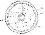
제2도는 제1도의 II-II선 단면도.2 is a cross-sectional view taken along the line II-II of FIG.
제3도는 피동결품의 출입구부의 상세도.3 is a detailed view of the entrance and exit of the driven product.
제4도는 피동결품의 접촉냉각을 설명하는 전개단면도.4 is a developed cross-sectional view illustrating contact cooling of a driven product.
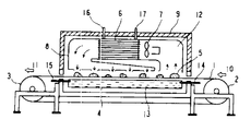
제5도는 종래의 동결장치를 표시하는 종단면 측면도.Figure 5 is a longitudinal cross-sectional side view showing a conventional freezing apparatus.
* 도면의 주요부분에 대한 부호의 설명* Explanation of symbols for main parts of the drawings
101 : 냉각판 102 : 염수조101: cooling plate 102: brine tank
105 : 냉각매체인냉염수 106 : 환상튜브105: cold saline as cooling medium 106: annular tube
106a : 가요성판 108 : 링프레임106a: flexible plate 108: ring frame
109 : 상부측 112 : 하부축109: upper side 112: lower axis
113 : 전동기 114, 117 : 기어113:
116 : 타이밍벨트 115 : 베어링부116: timing belt 115: bearing
그리고 도중 동일 부호는 동일 또는 상당부분을 표시한다.And the same code | symbol in the middle represents the same or an equivalent part.
본 발명은 식품 등의 피동결품을 모든 방면에서 냉각하여 급속하게 냉각 또는 동결하는 동결장치에 관한 것이다.The present invention relates to a freezing apparatus for rapidly cooling or freezing by cooling the frozen products such as food in all aspects.
종래의 이 종류의 동결장치에서는 제5도에 표시하는 것이 있었다. 도면에서 강철벨트(1)는 표면이 평활한 1매로된 스테인레스 강철벨트로 형성되어 있어 가변속모터에 직결한 구동폴리(3)가 제품출구(11)에 있으며 냉동시간의 조정을 자유로이 행할 수가 있다. 인장풀리(2)가 제품공급구(10)에 있어 강철벨트(1)에 일정한 인장력을 주고 았다.In the conventional freezing apparatus of this kind, there is a thing shown in FIG. In the drawing, the steel belt 1 is formed of a stainless steel belt having a smooth surface, so that the driving pulley 3 directly connected to the variable speed motor is located at the product outlet 11, and the freezing time can be adjusted freely. Tensile pulley (2) was given a constant tensile force on the steel belt (1) in the product supply port (10).
강철벨트(1)의 하측에는 염수조(brine tank)(4)가 접하고 있으며 강철벨트(1)의 상면에 피동결품(5)을 늘어놓는다. 또 그 상부에는 공기분사장치인 냉각핀(fin), 코일(6), 팬(fan)(7), 이 배치되어 송풍덕트(8)로 냉각공기의 순환통로를 형성하고 있다. 그리고 이들의 냉동구역(12)은 단열터널(9)내에 수용되어 있어 외부로부터의 열침입을 방지하고 있다.The brine tank (4) is in contact with the lower side of the steel belt (1) and the driven product (5) is arranged on the upper surface of the steel belt (1). In addition, a cooling fin (fin), a coil (6), a fan (7), which are air injectors, are arranged on the upper portion thereof to form a circulation passage for cooling air through the blowing duct (8). And these
염수조(4)에는 별도 설치한 염수 냉동기에 의하여 냉염수(13)가 냉염수입구(14)에서 공급되며 냉염수출구(15)에서 귀환하여 순환하게 된다. 또 냉각핀코일(6)에 대하여도 외부에 설치한 냉동기에의해 냉매가 냉매입구(16)에서 공급되며 냉매출구(17)에서 귀환하여 순환하게 된다.The brine tank 4 is supplied with the cold brine 13 by the brine freezer installed separately from the cold salt inlet 14 and is returned to the
다음에 이 종래의 동결장치의 동작에 대하여 설명한다. 동결장치의 제품공급구(10)에 피동결품(5)이 들어가면은 일정한 속도로 이동하는 강철벨트(1)와 함께 냉동구역(12)에 들어간다. 그 냉동구역(12)내에서 피동결품(5)은 염수조(4)내의 냉염수(13)에 의하여 냉냉각된 강철벨트(1)를 통하여 접촉덩결이 이루어진다. 한편 피동결품(5)의 상면에 대하여는 별도로 외부에 준비된 냉동기에 의하여 냉매의 공급을 받는 냉각핀코일(6)과 팬(7)에 의해 단열터널(9)내의 공기순환을 냉각하고 송풍덕트(8)에서 공기분사하여 냉각시킨다. 이와같이하여 동결 와료한 피동결품(5)은 단열터널(9)를 나와 다음처리로 반출된다.Next, the operation of the conventional freezing apparatus will be described. When the driven
종래의 동결장치는 이상과 같이 구성되어 있으므로 피동결품의 하면은 접촉냉각(contact freeze)에 의하여 급속동결되지만, 상면은 냉각고이를 분사하기 때문에 피동결품은 건조감량을 일으키는 동시에 냉각속도가 느리고 완만동결로 되어 제품의 품질저하가 되기 쉽다는 문제점이 있었다. 또 종래의 동결장치는 염수냉각과 공기분사방식의 2개방식을 채용하고 있으므로 냉동기 2대가 필요하며 원가가 커지는 동시에 운영비가 크다는 문제점이 있었다.Since the conventional freezing device is configured as described above, the lower surface of the driven product is rapidly frozen by contact freeze, but the upper surface is sprayed with a cooling freezer, which causes the loss of drying and at the same time the cooling rate is slow and slow freezing. There was a problem that it is easy to be the quality degradation of the product. In addition, since the conventional freezing apparatus employs two methods of salt cooling and air spraying, two freezers are required, and there is a problem that the operating cost is large and the cost is large.
이 발명은 상기와 같은 문제점을 해소하기 위한 것으로서 피동결품의 상면 및 측면을 하면과 마찬가지로 접촉냉각 시킬 수 있으며 또 그 피동결품의 접촉냉각을 컴팩트한 장치에 의하여 연속적으로 행하도록 동결장치를 얻는 것으로 목적으로 한다.The present invention has been made to solve the above problems, and the upper and side surfaces of the driven product can be contact cooled like the lower surface, and the object of the present invention is to obtain a freezing device to continuously perform the contact cooling of the driven product by a compact device. It is done.
이 발명의 관한 동결장치의 냉각판의 상면상에 피동결품을 올려놓고 가요성(可撓性) 판(flexible aheet)을 피동결품의 위로부터 씌워서 그 가요성판을 피동결품의 사면 및 측면에 접촉 시켜 냉각판의 하면측 및 가요성판의 상면측을 냉염수 등의 냉각매체에 의하여 동시에 냉각하도록 한 것이다.A passive article is placed on the upper surface of the cold plate of the freezing apparatus of the present invention, and a flexible plate is covered from above the driven article, and the flexible plate is brought into contact with the sides and sides of the passive article. The lower surface side of the cooling plate and the upper surface side of the flexible plate are simultaneously cooled by a cooling medium such as cold brine.
또 이 발명에 관한 다른 동결장치는 피동결품을 상면상에 올려놓는 냉각판을 수평으로 회전하는 회전식냉각판으로하여 가요성판에 의해 형성된 환상튜브를 피동결품의 위로부터 씌워 그 환상튜브를 피동결품의 상면 및 측면에 접촉 시켜 냉각판의 하면측 및 환상튜브의 내부를 냉염수 등의 냉각매체에 의하여 동시에 냉각하면서 냉각판 및 환상튜브를 동기하여 수평으로 회전하도록 한 것이다.Another freezing apparatus according to the present invention is a rotary cooling plate that rotates horizontally a cooling plate on which a driven product is placed on an upper surface thereof, covering an annular tube formed by a flexible plate from above the driven product, and placing the annular tube on the driven product. The cooling plate and the annular tube are rotated horizontally in synchronization with the upper surface and the side surface while simultaneously cooling the lower surface side of the cooling plate and the inside of the annular tube by a cooling medium such as cold brine.
이 발명에서 동결장치는 피동결품의 하면에 냉각판을 접촉시키는 동시에 피동결품의 상면 및 측면에 가요성판을 그 피동결품의 형상에 따르게하여 접촉시킬 수가 있다. 그리고 피동결품을 올려놓은 냉각판의 하면 및 환상튜브의 내부를 동시에 냉각하면서 이들 냉각판 및 환상튜브를 동기하여 수평회전 하므로 피동결품의 접촉냉각이 동시에 이루어진다. 더구나 피동결품을 수평회전시키면서 연속적으로 접촉냉각하는 동결장치는 피동결품을 벨트 컨베이어 방식에 의하여 직선적으로 반송하는 것에 비하여 컴팩트장치가 된다.In the present invention, the freezing apparatus can make the flexible plate come into contact with the upper and side surfaces of the driven product according to the shape of the driven product, while the cooling plate is brought into contact with the lower surface of the driven product. And while cooling the lower surface of the cooling plate and the annular tube at the same time, the cooling plate and the annular tube is rotated horizontally in synchronism, so that the contact cooling of the passive product is achieved at the same time. In addition, the freezing device for continuously contact-cooling while rotating the driven product horizontally becomes a compact device as compared to linearly conveying the driven product by a belt conveyor method.
이하 이 발명의 동결장치의 한 예를 도면에 의하여 설명한다.Hereinafter, an example of the freezing apparatus of this invention is demonstrated by drawing.
제1도 및 제2도에 있어서, 101은 수평으로 설치된 원형의 냉각판이며, 102은 냉각판(101)의 하부에 수평으로 설치된 염수조, 104은 염수조(102)의 외측에서 하부로 설치된 염수수판, 103은 염수조(102)로 냉각매체인 냉염수(105)를 도입하는 복수의 염수도입관이다.In FIG. 1 and FIG. 2, 101 is a horizontal cooling plate installed horizontally, 102 is a salt bath installed horizontally in the lower part of the
106은 가요성판에 의해 형성된 환상튜브이며 이 환상튜브(106)는 냉각판(101)의 상면상에 수평으로 설치되며 또한 내부에는 냉각매체인 냉염수(105)가 충만 된다.106 is an annular tube formed by a flexible plate, and the
108은 환상튜브(106)의 상부에 수평으로 설치된 다중링구조의 링프레임(ring frame)이며, 107은 환상튜브(106)의 내주 및 외주를 각각 등간격으로 링프레임(108)에 보지시킨 각각 12개 합계 24개의 판홀더(holder)이다.108 is a ring frame of a multi-ring structure horizontally installed on the upper portion of the
109은 링프레임(108)이 장착된 상부축, 110은 환상튜브(106)내에 냉염수(105)를 도입하는 염수도입관, 111은 환상튜브(106)내부에서 냉염수(105)를 도출하는 염수도출관이며, 112은 냉각판(101)과 염수조(102)와 염수수판(104)과 상부축(109)이 각각 동일축선 상태에 장착된 하부축이다.109 is an upper shaft on which the
113은 하부축(112)을 회전구동하는 전동기, 114은 전동기(103)의 구동축에 장착된 기어(gear), 117은 하부축(112)에 장착된 기어이며, 양기어(114)와(117)간에 걸려있는 타이밍 벨트이다.113 is an electric motor for rotating the
115은 하부축(112)의 베어링, 121 및 122는 하부축(112)에 설치된 염수도입관 및 염수도출관, 119 및 120은 외부설치의 염수열교환기(도시 생략)와 접속되어있는 염수입구관 및 염수출구관이며, 118은 염수도입관(121)과 염수도출관(122)을 염수입구관(119)과 염수출구관(120)의 하단에 각각 접속한 로터리 조인트(rotary joint)이다.115 is a bearing of the
염수도입관(121)과 염수도출관(122)의 상단이 염수도입관(110)과 염수도출관(111)에 각각 접속되어 있으며 중간에 염수도입관이 접속되어, 염수도출관(122)의 중간에 염수수판(104)의 하단이 접속되어 있다.The
123은 피동결품(5)의 출입구부이며, 124는 장치전체의 커버이며, 125는 염수수판(104)의 하부외주를 지지하고 있는 다수의 롤러(roller)이다.123 is an entrance and exit part of the driven
제3도는 피동결품(5)의 출입구부의 상세도이며, 221은 환상튜브(106)를 하방으로부터 들어올리는 원호상의 리프트판, 222는 리프트판(106)을 상하로 승강시키는 리프터, 223은 리프트판(221)의 표면상에 장착된 다수의 롤러이다.3 is a detailed view of the entrance and exit portion of the driven
다음에 이 발명의 동결장치에 의한 피동결품(5)의 연속적인 동결동작에 관하여 설명한다.Next, the continuous freezing operation of the driven
먼저 열교환기에 의하여 냉각된 냉염수(105)가 염수입구관(119)에서 로터리조인트(118)를 통하여 염수도입관(121)으로 도입된다. 염수도입관(121)내에 도입된 냉염수(105)는 염수도입관(103) 및 (110)을 통하여 염수조(102) 및 환상튜브(106)의 내부에 각각 도입된다.First, the
한편 염수조(102)내의 냉염수(105)는 그 염수조(102)의 외주상부 언저리와 냉각판(101)사이의 간극에서 넘쳐흘러 염수수판(104)에서 회수되어서 염수도출관(122)내에 들어가며 환상튜브(106)내의 냉염수(105)는 염수도출관(111)에서 염수도출관내(122)로 흡입된다. 그리고 이들 염수도출관(122)내에 도입된 냉염수(105)는 로터리조인트(118), 염수출구관(120)을 통하여 펌프(외부 설치)에 의해 퍼내어져 열교환기로 송출된다. 따라서 염수조(102)와 환상튜브(106)내와 열교환기와의 사이에서 냉염수(105)가 순환되어서 염수조(102) 및 환상튜브(106)의 내부가 저온으로 유지되고 냉각판(101)이 하방으로부터 냉각되는 동시에 환상튜브(106)가 내부로부터 냉각된다.Meanwhile, the cold brine 105 in the
다음에 이 냉염수(105)의 순환에 의한 냉각판(101) 및 환상튜브(106)의 냉각동작과 동시에 이들 냉각판(101) 및 환상튜브(106)가 서로 동기되어서 동일방향에 수평으로 구동된다.Next, at the same time as the cooling operation of the
즉, 전동기(113)의 작동에 의하여 기어(114), 타이밍벨트(116) 및 기어(114)를 통하여 하부축(112)이 회전구동되어 그 하부축(112)에 의하여 냉각판(101) 염수조(102) 및 염수수판(104)이 일체가 되어서 예를들면 제2도에서 화살표 a 방향에 수평으로 회전구동된다.That is, the
또 하부축(114)과 일체로 상부축(109) 및 링프레임(108)이 회전구동되어서 판홀더(107)에 의하여 링프레임(108)이 보지되어 있는 환상튜브(106)가 냉각판(101)에 동기하여 역시 제2도에서 화살표 a 방향에 수평으로 회전구동된다. 그리고 이때 염수도입관(121) 및 염수도출관(122)은 하부축(112)과 일체로 회전되지만 이들은 로터리조인트(118)에 의하여 염수입구관(119) 및 염수출구관(120)에 접속되어 있으므로 냉염수(105)의 순환동작은 하부축(112)의의 회전에 의하여 하등 지장받는 일이 없다.In addition, the
다음에 상기와 같이 수평으로 회전되고있는 냉각판(101)의 상면상으로의 피동결품(5)의 반입반출은 출입구부(123)에 있어서 제3도에 표시된 바와 같이 행하여진다.Next, the carry-in / out of the driven
즉 리프터(lifter 222)에의하여 리프트(lift)판(211)이 상방으로 들어올려지면 그 리프트판(221)에 의하여 환상튜브(106)의 하면측이 들어올려져서 냉각판(101)의 상면상에서 상방으로 떨어져 그냉각판(101)의 상면상과 환상튜브(106)사이의 공간부(224)가 만들어진다.That is, when the lift plate 211 is lifted upward by the
그때 지금부터 동결시킬 피동결품(5)을 그 공간부내에 화살표 b 방향으로 반입하는 동시에 동결이 끝난 피동결품(5)을 그 공간부(224)내로부터 화살표 c 방향으로 반출한다. 그리고 이 동결품(5)의 반입반출사이에 있어서도 냉각판(101) 및 환상튜브(106)는 화살표 a 방향에 회전하고 있으며 환상튜브(106)는 리프트판(221) 표면상에 장치되어 있는 다수의 롤러(223)에 의하여 원활히 안내되어서 그 리프트판(221)의 표면상을 원활하게 타고 넘어서 화살표 a 방향으로 회전해간다. 그리고 냉각판(101)의 상면상에 반입된 피동결품(5)은 제4도에 표시된바와 같이 화살표 a 방향에 회전하고 있는 냉각판(101)과 환상튜브(106)사이에 순차 끼어들어가게 된다.At this time, the
즉 냉각판(101)의 상면상에 올려놓은 피동결품(5)의 위로부터 환상튜브(106)의 저면을 형성하고 있는 가요성판(106a)이 위로부터 씌워져 그 피동결품(5)의 상면 및 측면에 가요성판(106a)이 그 피동결품(5)의 형상에 따르며 접촉된다. 이 결과 피동결품(5)은 냉각판(101)과 가요성판(106a)에 의하여 대략 모든 방면으로부터 급속하게 냉각 또는 동결된다.That is, the flexible plate 106a, which forms the bottom surface of the
이상과 같이 동결장치에 의하면 피동결품(5)을 냉각판(101)의 상면상에서 제2도에 표시한 화살표 a 방향으로 순차연속적으로 회전 반송하면서 그 피동결품(5)을 대략 모든 방면으로부터 접촉 냉각하여 급속히 냉각 또는 동결시킬 수가 있다.As described above, according to the freezing device, the driven
이상 이 발명의 실시예에 관하여 기술하였는데 이 발명은 상기 실시예에 한정되지 않고 이 발명의 기술적 사상의 기준하여 각종 유효한 변경이 가능한 것이다.As mentioned above, although the Example of this invention was described, this invention is not limited to the said Example, A various effective change is possible based on the technical idea of this invention.
예를들면 상기 실시예에서는 냉각판(101) 및 환상튜브(106)는 원형상의 것을 표시하였지만 양자는 다각형(6각형, 8각형등)상의 것이라도 된다. 또 염수도입관(121) 및 염수도출관(122)은 하부축(112)내에서 계별배관으로 평행하게 설치한 것을 표시하였지만 동축의 2중관 방식이라도 된다. 환상튜브(106)내의 염수도입관(110) 및 염수도출관(111)은 가 1개의 것을 표시하였지만 각각 복수개로 하여도 된다.For example, in the above embodiment, the
하부축(121)의 구동으로서 타이밍벨트(116)에 의한 것을 표시하였지만 체인 방식, 벨트방식, 기어직결방식의 것도 된다. 하부축(121)의 베어링부(115)는 회전베어링의 것을 표시하였지만 슬라이딩 베어링도 된다. 또 냉각매체는 냉염수 이외의 것이라도 무방하다.Although the
이상과 같이 이 발명에 의하면 냉가판에 의하여 하면이 접촉냉각되는 피동결품의 상면 및 측면을 가요성판에 의하여 접촉냉각하도록하여 그 피동결품의 냉각속도를 빨리 할 수가 있다. 따라서 피동결품의 냉각 또는 동결을 단시간내에 매우 효율적으로 실시 할 수가 있으므로 제품의 품질저하를 초래하는 일이 없다. 또 이 발명의 다른 실시예에 의하면 냉각판 및 가요성판에 의하여 형성한 환상튜브를 서로 동기하여 수평으로 회전하도록하여 피동결품을 냉각판과 환상튜브사이에 순차 끼워넣어 회전시키면서 전술한 대략 모든 방면으로부터의 접촉냉각이 되도록 구성하였으므로 피동결품의 급속한 냉각 또는 동결을 순차 연속적으로 실시하는 외에 종래의 벨트 컨베니어방식에 의한것에 비하여 장치전체의 컴팩트화 및 공간절약화를 도모할 수 가 있다.As described above, according to the present invention, the upper surface and the side surface of the driven product to which the lower surface is in contact cooling by the cold plate can be contact-cooled by the flexible plate, so that the cooling speed of the driven product can be increased. Therefore, the cooling or freezing of the passive product can be performed very efficiently within a short time, so that the quality of the product is not degraded. According to another embodiment of the present invention, the annular tube formed by the cooling plate and the flexible plate is rotated horizontally in synchronization with each other, thereby inserting and rotating the driven product between the cooling plate and the annular tube sequentially from almost all the above-mentioned aspects. Since it is configured to be in contact cooling, rapid cooling or freezing of the driven product can be carried out continuously, and the whole device can be made compact and space can be saved as compared with the conventional belt conveyor system.
Claims (2)
Applications Claiming Priority (3)
| Application Number | Priority Date | Filing Date | Title |
|---|---|---|---|
| JP61125537A JPS62284166A (en) | 1986-05-30 | 1986-05-30 | Freezing device |
| JP125537 | 1986-05-30 | ||
| JP61-125537 | 1986-05-30 |
Publications (2)
| Publication Number | Publication Date |
|---|---|
| KR870011437A KR870011437A (en) | 1987-12-23 |
| KR900008855B1 true KR900008855B1 (en) | 1990-12-11 |
Family
ID=14912648
Family Applications (1)
| Application Number | Title | Priority Date | Filing Date |
|---|---|---|---|
| KR1019870000493A KR900008855B1 (en) | 1986-05-30 | 1987-01-22 | Freezing apparatus |
Country Status (4)
| Country | Link |
|---|---|
| US (1) | US4760712A (en) |
| JP (1) | JPS62284166A (en) |
| KR (1) | KR900008855B1 (en) |
| AU (1) | AU591982B2 (en) |
Cited By (1)
| Publication number | Priority date | Publication date | Assignee | Title |
|---|---|---|---|---|
| KR101228800B1 (en) * | 2013-01-04 | 2013-01-31 | 김평경 | Apparatus for individual quick-freezing |
Families Citing this family (7)
| Publication number | Priority date | Publication date | Assignee | Title |
|---|---|---|---|---|
| KR910004395B1 (en) * | 1987-03-18 | 1991-06-27 | 미쓰비시전기 주식회사 | Freezing apparatus |
| US5213029A (en) * | 1991-03-28 | 1993-05-25 | Kabushiki Kaisha Kobe Seiko Sho | Apparatus for treating food under high pressure |
| US5275016A (en) * | 1992-04-24 | 1994-01-04 | Abaxis, Inc. | Cryogenic apparatus |
| GB9306301D0 (en) * | 1993-03-26 | 1993-05-19 | Boc Group Plc | Freezing apparatus and method |
| US5860282A (en) * | 1997-07-24 | 1999-01-19 | Winterlab Limited | Process for preparing ice substitutes |
| DK176279B1 (en) * | 2005-02-16 | 2007-06-04 | Slagteriernes Forskningsinst | Method, apparatus and cooling element for cooling carcass parts |
| WO2013070359A2 (en) * | 2011-11-10 | 2013-05-16 | Miller Michael M | Combined impingement/plate freezer |
Family Cites Families (7)
| Publication number | Priority date | Publication date | Assignee | Title |
|---|---|---|---|---|
| JPS5431852B2 (en) * | 1974-10-18 | 1979-10-09 | ||
| JPS6020671B2 (en) * | 1978-01-13 | 1985-05-23 | 昭和炭酸株式会社 | Rapid freezing method and equipment for food |
| JPS555022A (en) * | 1978-06-23 | 1980-01-14 | Sumitomo Electric Industries | Method of carrying bellows type oil tanker |
| NL7810089A (en) * | 1978-10-06 | 1980-04-09 | Gist Brocades Nv | COOLING DEVICE. |
| JPS5960166A (en) * | 1982-09-27 | 1984-04-06 | 三菱電機株式会社 | Freezer |
| NZ209594A (en) * | 1983-09-27 | 1987-03-06 | Mitsubishi Electric Corp | Conveyor for continuous freezing with belt conveyer filled with cold brine |
| KR900001179Y1 (en) * | 1984-02-23 | 1990-02-17 | 미쓰비시전기주식회사 | Cooling apparatus |
-
1986
- 1986-05-30 JP JP61125537A patent/JPS62284166A/en active Granted
-
1987
- 1987-01-22 KR KR1019870000493A patent/KR900008855B1/en not_active IP Right Cessation
- 1987-05-08 US US07/047,391 patent/US4760712A/en not_active Expired - Fee Related
- 1987-05-21 AU AU73254/87A patent/AU591982B2/en not_active Ceased
Cited By (1)
| Publication number | Priority date | Publication date | Assignee | Title |
|---|---|---|---|---|
| KR101228800B1 (en) * | 2013-01-04 | 2013-01-31 | 김평경 | Apparatus for individual quick-freezing |
Also Published As
| Publication number | Publication date |
|---|---|
| KR870011437A (en) | 1987-12-23 |
| AU7325487A (en) | 1987-12-03 |
| AU591982B2 (en) | 1989-12-21 |
| US4760712A (en) | 1988-08-02 |
| JPH0423191B2 (en) | 1992-04-21 |
| JPS62284166A (en) | 1987-12-10 |
Similar Documents
| Publication | Publication Date | Title |
|---|---|---|
| US5170631A (en) | Combination cryogenic and mechanical freezer apparatus and method | |
| KR900008855B1 (en) | Freezing apparatus | |
| KR870001257B1 (en) | Freezing apparatus | |
| US20100050656A1 (en) | Continuous food product cooling system | |
| US5398521A (en) | Commercial freezer | |
| EP0372354B1 (en) | Tunnel freezer | |
| US2794326A (en) | Method and apparatus for cooling canned goods | |
| US3832864A (en) | Quick-freezing machine | |
| US4628615A (en) | Process and installation for the heat treatment of cylindrical bodies, especially pipes | |
| RU2113665C1 (en) | Tunnel quick-freezer | |
| CN214830485U (en) | Fire dipping equipment for steel ball production | |
| US3964734A (en) | Apparatus for thermally treating metal components | |
| US4077814A (en) | Method for thermally treating metal components | |
| JPH03102164A (en) | Cooling or freezing device | |
| SU1717914A1 (en) | Method of refrigerated processing of foods | |
| RU2284438C2 (en) | Freezing method and air chamber for rapid food product freezing | |
| JP2704504B2 (en) | Multi-stage freezer | |
| US1795330A (en) | Freezing apparatus | |
| JP2002068436A (en) | Carrier processing device of food | |
| JPH0629651Y2 (en) | Conveyor type refrigeration equipment | |
| SU807007A1 (en) | Quick-freezing apparatus | |
| JPH03102165A (en) | Cooling or freezing device | |
| SU738578A1 (en) | Apparatus for smoking and drying food products | |
| SU1143951A1 (en) | Freezing apparatus | |
| JP4152675B2 (en) | Food processing equipment |
Legal Events
| Date | Code | Title | Description |
|---|---|---|---|
| A201 | Request for examination | ||
| E902 | Notification of reason for refusal | ||
| G160 | Decision to publish patent application | ||
| E701 | Decision to grant or registration of patent right | ||
| GRNT | Written decision to grant | ||
| FPAY | Annual fee payment |
Payment date: 19931201 Year of fee payment: 4 |
|
| LAPS | Lapse due to unpaid annual fee |