KR900008664B1 - Liquid sampling bench - Google Patents
Liquid sampling bench Download PDFInfo
- Publication number
- KR900008664B1 KR900008664B1 KR8204772A KR820004772A KR900008664B1 KR 900008664 B1 KR900008664 B1 KR 900008664B1 KR 8204772 A KR8204772 A KR 8204772A KR 820004772 A KR820004772 A KR 820004772A KR 900008664 B1 KR900008664 B1 KR 900008664B1
- Authority
- KR
- South Korea
- Prior art keywords
- container
- liquid sampling
- sampling bench
- liquid
- needle
- Prior art date
Links
Images


Classifications
-
- G—PHYSICS
- G01—MEASURING; TESTING
- G01N—INVESTIGATING OR ANALYSING MATERIALS BY DETERMINING THEIR CHEMICAL OR PHYSICAL PROPERTIES
- G01N1/00—Sampling; Preparing specimens for investigation
- G01N1/02—Devices for withdrawing samples
- G01N1/10—Devices for withdrawing samples in the liquid or fluent state
-
- G—PHYSICS
- G21—NUCLEAR PHYSICS; NUCLEAR ENGINEERING
- G21C—NUCLEAR REACTORS
- G21C7/00—Control of nuclear reaction
- G21C7/02—Control of nuclear reaction by using self-regulating properties of reactor materials, e.g. Doppler effect
- G21C7/04—Control of nuclear reaction by using self-regulating properties of reactor materials, e.g. Doppler effect of burnable poisons
-
- G—PHYSICS
- G21—NUCLEAR PHYSICS; NUCLEAR ENGINEERING
- G21F—PROTECTION AGAINST X-RADIATION, GAMMA RADIATION, CORPUSCULAR RADIATION OR PARTICLE BOMBARDMENT; TREATING RADIOACTIVELY CONTAMINATED MATERIAL; DECONTAMINATION ARRANGEMENTS THEREFOR
- G21F7/00—Shielded cells or rooms
- G21F7/06—Structural combination with remotely-controlled apparatus, e.g. with manipulators
-
- G—PHYSICS
- G01—MEASURING; TESTING
- G01N—INVESTIGATING OR ANALYSING MATERIALS BY DETERMINING THEIR CHEMICAL OR PHYSICAL PROPERTIES
- G01N1/00—Sampling; Preparing specimens for investigation
- G01N1/02—Devices for withdrawing samples
- G01N1/10—Devices for withdrawing samples in the liquid or fluent state
- G01N2001/1031—Sampling from special places
- G01N2001/1037—Sampling from special places from an enclosure (hazardous waste, radioactive)
-
- G—PHYSICS
- G01—MEASURING; TESTING
- G01N—INVESTIGATING OR ANALYSING MATERIALS BY DETERMINING THEIR CHEMICAL OR PHYSICAL PROPERTIES
- G01N1/00—Sampling; Preparing specimens for investigation
- G01N1/02—Devices for withdrawing samples
- G01N1/10—Devices for withdrawing samples in the liquid or fluent state
- G01N1/20—Devices for withdrawing samples in the liquid or fluent state for flowing or falling materials
- G01N1/2035—Devices for withdrawing samples in the liquid or fluent state for flowing or falling materials by deviating part of a fluid stream, e.g. by drawing-off or tapping
- G01N2001/2071—Removable sample bottle
- G01N2001/2078—Pre-evacuated bottle
-
- G—PHYSICS
- G01—MEASURING; TESTING
- G01N—INVESTIGATING OR ANALYSING MATERIALS BY DETERMINING THEIR CHEMICAL OR PHYSICAL PROPERTIES
- G01N33/00—Investigating or analysing materials by specific methods not covered by groups G01N1/00 - G01N31/00
- G01N2033/0093—Investigating or analysing materials by specific methods not covered by groups G01N1/00 - G01N31/00 radioactive materials
-
- G—PHYSICS
- G01—MEASURING; TESTING
- G01N—INVESTIGATING OR ANALYSING MATERIALS BY DETERMINING THEIR CHEMICAL OR PHYSICAL PROPERTIES
- G01N35/00—Automatic analysis not limited to methods or materials provided for in any single one of groups G01N1/00 - G01N33/00; Handling materials therefor
- G01N35/02—Automatic analysis not limited to methods or materials provided for in any single one of groups G01N1/00 - G01N33/00; Handling materials therefor using a plurality of sample containers moved by a conveyor system past one or more treatment or analysis stations
- G01N35/04—Details of the conveyor system
- G01N2035/0474—Details of actuating means for conveyors or pipettes
- G01N2035/0479—Details of actuating means for conveyors or pipettes hydraulic or pneumatic
- G01N2035/0481—Pneumatic tube conveyors; Tube mails; "Rohrpost"
-
- Y—GENERAL TAGGING OF NEW TECHNOLOGICAL DEVELOPMENTS; GENERAL TAGGING OF CROSS-SECTIONAL TECHNOLOGIES SPANNING OVER SEVERAL SECTIONS OF THE IPC; TECHNICAL SUBJECTS COVERED BY FORMER USPC CROSS-REFERENCE ART COLLECTIONS [XRACs] AND DIGESTS
- Y02—TECHNOLOGIES OR APPLICATIONS FOR MITIGATION OR ADAPTATION AGAINST CLIMATE CHANGE
- Y02E—REDUCTION OF GREENHOUSE GAS [GHG] EMISSIONS, RELATED TO ENERGY GENERATION, TRANSMISSION OR DISTRIBUTION
- Y02E30/00—Energy generation of nuclear origin
- Y02E30/30—Nuclear fission reactors
Abstract
내용 없음.No content.
Description
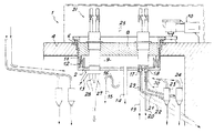
제1도는 본 발명에 따른 샘플링 벤치의 수직 단면도.1 is a vertical sectional view of a sampling bench according to the invention.
제2도는 콘테이너를 도입 및 조작하기 위한 기계적 장치의 평면도.2 is a plan view of a mechanical device for introducing and manipulating containers.
제3도는 제2도의 III-III선 수직 단면 확대도.3 is an enlarged vertical cross-sectional view taken along line III-III of FIG.
제4도는 장치내로의 콘테이너-슬라이드 조립체의 도입을 설명하는 콘테이너용 기계적 취급장치의 상부단면도.4 is a top sectional view of a mechanical handling device for a container illustrating the introduction of a container-slide assembly into the device.
제5도는 기계적 장치의 하부내의 그런 조립체를 도시하는 단면도.5 is a cross-sectional view illustrating such an assembly within the bottom of the mechanical device.
제6도는 슬라이드 내 콘테이너를 도시하는 개략도.6 is a schematic diagram illustrating containers in a slide.
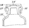
제7도는 샘플링 콘테이너용 탄성 플러그의 특수 실시예의 단면도.7 is a cross-sectional view of a particular embodiment of an elastic plug for a sampling container.
* 도면의 주요부분에 대한 부호의 설명* Explanation of symbols for main parts of the drawings
2 : 용기 4 : 보호 슬랩2: container 4: protective slab
6 : 원형링 8 : 회전플러그6: circular ring 8: rotation plug
10 : 전기모우터 11 : 슬리이브10: electric motor 11: a sleeve
12 : 리셉터클 15 : 유출액배출관12: Receptacle 15: Outflow liquid discharge pipe
16 : 사이폰 17, 18 : 니이들 단부 피팅16: siphon 17, 18: needle end fitting
19, 20, 21, 22 : 덕트 23, 24 : 분리기19, 20, 21, 22:
25 : 회전축 31 :기계장치25: rotating shaft 31: mechanical device
32 : 헬리컬 스프링 37 : 피니온32: helical spring 37: pinion
38 : 랙 40 : 콘테이너-슬라이드 조립체38
43 : 피스톤 50 : 니이들43: piston 50: needle
51 : 콘테이너 52 : 원통형 슬리이브 또는 슬라이드51 container 52 cylindrical sleeve or slide
55 : 탄성플러그55: elastic plug
본 발명은 액체 샘플링 벤치, 특히 방사성 액체 샘들을 채취하기 위한 벤치에 관한 것이다.The present invention relates to a liquid sampling bench, in particular a bench for collecting radioactive liquid fountains.
조사된(irradiated)연료의 처리용 화학 유닛내에서의 방사성 용액 샘플의 원격 채취는 소위 "샘플링 벤치"에 의해 수행된다.Remote sampling of radioactive solution samples in a chemical unit for the treatment of irradiated fuel is performed by a so-called "sampling bench".
샘플링될 방사성 액체를 보유하는 용기는 그 상부가 작업면으로 작용하는 생물학적 보호 슬랩 하방에 배치된다. 용기들은 수십미터의 거리로 배치된다. 샘플링될 액체는 이 용기로부터 샘플링 벤치의 레벨까지 상승되며 가급적 연속적으로 순환한다. 가요성 및 탄성인 재료로 제조되는 사전에 진공하에 놓인 저그(jug) 또는 포트(pot)라 불리우는 콘테이너의 플러그는 그 단부에서 샘플링될 액체 분류에 연결된 니이들에 의해 맞추어진다. 충전 후, 콘테이너는 샘플링 벤치로부터 분석실험실로 전달된다. 이런 벤치들은 프랑스공학국 특허 제 1401298호, 제 1401405호 및 프랑스공화국 특허 제 1401298호의 추가 특허인 제 2058751호에 기재되어 있다. 이 공지된 벤치는 주로 글로우브 박스내에 투입할 방사성 액체를 보유하는 용기에 연결된 중공 니이들 단부 피팅에 의해 일련의 액체 유입부와 글로우브 박스내에 콘테이너를 도입하여 글로우브 박스로부터 콘테이너를 제거하기 위한 수단을 가짐으로써 취급수단이 글로우브 박스내로 콘테이너를 변위시킬 수 있게 한다. 취급수단은 공구호울더에 고정되며 일반적으로 3가지 형식, 즉 니이들 유입단부 피팅용 언플러깅공구(unplugging tool), 콘테이너 취급 공구 및 니이들 제거 및 재장착용 공구이다.The container holding the radioactive liquid to be sampled is placed underneath a biological protective slab whose upper side acts as a working surface. The containers are arranged at a distance of several tens of meters. The liquid to be sampled is raised from this vessel to the level of the sampling bench and circulated as continuously as possible. A plug of a container, called a jug or pot, previously placed under vacuum, made of a flexible and elastic material, is fitted by needles connected to the liquid fraction to be sampled at its end. After filling, the container is transferred from the sampling bench to the assay laboratory. These benches are described in French Patent No. 1401298, 1401405 and French Patent No. 2058751, which are additional patents of French Patent No. 1401298. This known bench is mainly intended for removing containers from the glove box by introducing containers into the series of liquid inlets and the glove box by hollow needle end fittings connected to the vessel holding the radioactive liquid to be put into the glove box. Having the means allows the handling means to displace the container into the glove box. The handling means are fixed to the tool holder and are generally three types: unplugging tool for needle inlet fitting, container handling tool and needle removal and remounting tool.
이런 벤치에서, 단부 피팅의 단부는 적어도 1개의 원호에 따라서 배치된다. 이 단부 피팅 상방과 글로우브 박스내에 제1축에 대해 회전하는 지지체가 있다. 상기 지지체 상태에서 공구 호울더는 제1축과 상이한 제2축에 대해 회전할 수 있으며, 상기 공구 호울더는 또한 제2축을 따라서 이동할 수 있다. 샘플링을 하기 위해 사용될 공구는 제2축과 중심을 벗어나 평행하며 동거리인 위치의 공구 호울더상에 배치된다.In this bench, the ends of the end fittings are arranged along at least one arc. There is a support that rotates about the first axis above the end fitting and in the glove box. In the support state, the tool holder can rotate about a second axis different from the first axis, and the tool holder can also move along the second axis. The tool to be used for sampling is placed on a tool holder at a position parallel and equidistant off center with the second axis.
프랑스공화국 추가 특허 제 2058751호는 용이하게 교환가능한 짧은 니이들 단부 피팅에 관한 다수의 개량에 대해 기술하고 있다.The Republic of France Additional Patent No. 2058751 describes a number of improvements with regard to short needle end fittings that are easily interchangeable.
이 샘플링 벤치는 정확히 작동하지만, 여러가지 결점도 가지고 있다. 우선, 상기 형식의 벤치는 콘크리트로 만든 생체학적 보호 슬랩 상방에 배치된 글로우브 박스내에 배치된다.This sampling bench works correctly, but also has several drawbacks. First of all, the bench of this type is placed in a glove box placed above a bioprotective slab made of concrete.
알파 입자에 대한 보호를 위해서, 공구와 글로우브 상자의 패널의 시스템이 가스킷과 함께 설치된다. 그리고 감마선에 대한 보호를 위해서, 공구의 상부 기계부가 적어도 7㎝의 납에 의한 보호와 상응하는 고체부재로써 형성되어야 할 필요가 있다.For protection against alpha particles, a system of tools and a panel of glove boxes is installed with the gasket. And for protection against gamma rays, the upper mechanical part of the tool needs to be formed of a solid member corresponding to the protection by at least 7 cm of lead.
그리고 벤치의 주변은 납판에 의해 둘러싸지며 작업축상의 면은 글로우브 박스 내에서 조작하기 위한 집게와 구멍을 구비한다. 이경우, 글로우브 박스와 그 생체학적 보호수단은 장애가 되고 무거운 조립체를 형성한다.The periphery of the bench is surrounded by a lead plate and the face on the working shaft has tongs and holes for operation in the glove box. In this case, the glow box and its bioprotective means become obstructive and form a heavy assembly.
제 2058751호의 추가 특허는 충전된 콘테이너의 자동추출과 공기식 배출수단에 의한 용기 벤치 밖으로의 그 운반을 제안한다.A further patent of 2058751 proposes the automatic extraction of filled containers and their transport out of the container bench by pneumatic discharge means.
이 목적으로 콘테이너의 조정 및 제거를 위한 기계적 장치가 설명되며 그것은 슬라이드내에 콘테이너를 자동적으로 제한할 수 있으며 콘테이너-슬라이드 조립체를 공기식으로 제거할 수 있다. 이 기계적 장치는 상당히 복잡하며, 장치 시스템의 신뢰도를 증가시키기 위해서 그 수효를 제한하는 것이 바람직하다.For this purpose a mechanical device for the adjustment and removal of a container is described which can automatically limit the container within the slide and pneumatically remove the container-slide assembly. This mechanical device is quite complex and it is desirable to limit its number in order to increase the reliability of the device system.
그리고 전술한 벤티에서, 단부 피팅은 수직 배치되는 대신에 임의의 경사를 가진다. 공구는 또한 수직에 대해 임의의 경사를 가지며 경사측에 따라 작동한다. 전술한 특허에 기재된 수개의 단부 피팅을 갖는 벤치의 설계에 의해 필요한 이 장치는 정확한 위치 결정과 정밀한 기계구조를 필요로 하는데, 그 신뢰도는 적당하지 못하다. 최종적으로, 충전 후 콘테이너가 니이들 단부 피팅으로부터 제거될 때 액적(drop)이 니이들에 의해 천공된 가요성이며 탄성인 플러그의 외면뒤에 놓이며 상기 액정은 위험한 오염원이 될수 있다.And in the aforementioned venti, the end fittings have any inclination instead of being vertically placed. The tool also has any inclination with respect to the vertical and operates along the inclination side. This device, which is required by the design of a bench with several end fittings described in the above patents, requires accurate positioning and precise mechanical construction, the reliability of which is not adequate. Finally, when the container is removed from the needle end fitting after filling, a drop is placed behind the outer surface of the flexible and elastic plug perforated by the needle and the liquid crystal can be a hazardous source of contamination.
본 발명은 글로우브 상자를 제거함으로써 상기 결점을 제거하며 기계적 장치와 수효가 제한된 샘플링 벤치에 관한 것이다.The present invention is directed to a sampling bench that eliminates this drawback by removing the glove box and which has a limited number of mechanical devices.
본 발명에 의한 샘플링 벤치의 주요 특징에 따르면, 그 특징은 샘플링이 탄성 플러그에 의하여 밀봉된 콘테이너 또는 저그를 가지고 수행되며, 그 탄성 플러그는 샘플링될 액체를 보유한 저장조에 연결된 중공 니이들 상에 천공되고 생체학적 보호 슬랩 하방에 위치하며, 보호 슬랩의 하방에 위치하고 보호 슬랩과 일체인 밀봉 용기를 포함하며 중공 니이들의 단부 피팅이 내장되는 한편 콘테이너의 도입 및 조작용 기계장치가 적어도 1개 있으며 그 장치의 적어도 하부는 슬랩을 횡단하고 니이들 단부 피팅 상방의 용기에서 종료된다.According to the main feature of the sampling bench according to the invention, the feature is performed with the container or jug sealed by an elastic plug, the elastic plug being perforated on a hollow needle connected to a reservoir holding the liquid to be sampled. Located below the biological protective slab, including a sealed container located below the protective slab and integral with the protective slab, with end fittings of the hollow needles embedded therein and at least one mechanism for the introduction and operation of the container; At least the lower portion of the crosses the slab and terminates in a vessel above the needle end fitting.
본 발명의 바람직한 실시예에 따라서, 슬랩은 전술한 용기 상방에 배치된 회전 플러그를 가지며, 니이들 단부 피팅은 원호 또는 수개의 동심 원호에 따라서 배치됨으로써 플러그의 회전축이 이 원의 중심을 통과하도록 한다. 이경우, 콘테이너의 도입 및 취급용 기계장치는 회전 플러그를 횡단하며 앞에서 정의한 원의 반경과 동등한 거리만큼 플러그 회전축으로부터 떨어져 배치된 적어도 1개의 공구 호울더를 구비한다. 취급을 용이하게 하고 공기 시스템에 의한 그 전달을 허용하도록 콘테이너는 "슬라이드"라고 불리우는 리셉터클 내에 배치되며 콘테이너-슬라이드 조립체는 벤치 내에서 변위된다.According to a preferred embodiment of the present invention, the slab has a rotary plug disposed above the vessel, and the needle end fitting is arranged along an arc or several concentric arcs such that the axis of rotation of the plug passes through the center of the circle. . In this case, the mechanism for introduction and handling of the container has at least one tool holder which traverses the rotary plug and is arranged away from the plug axis of rotation by a distance equal to the radius of the circle defined above. The container is placed in a receptacle called a "slide" and the container-slide assembly is displaced within the bench to facilitate handling and allow its transfer by the air system.
본 발명에 따른 샘플링 벤치의 최종적인 특징에 따라서, 각 콘테이너용 기계 취급장치는 회전이 자유롭고 병진 방향으로는 움직이지 않는 적어도 1개의 수직 헬리컬 나사를 가지며, 콘테이너-슬라이드 조립체가 하향축을 따라서 변위할 수 있고, 파지 공구(gripping tool)와 드럼 또는 실린더는 하향축과 파지 공구 사이에서 콘테이너-슬라이드 조립체가 변위할 수 있다.According to the final feature of the sampling bench according to the invention, the machine handling device for each container has at least one vertical helical screw which is free to rotate and does not move in the translational direction, allowing the container-slide assembly to displace along the downward axis. And the gripping tool and the drum or cylinder may displace the container-slide assembly between the downward axis and the gripping tool.
본 발명의 다른 특징과 장점은 첨부 도면을 참고로 하여 비제한적인 실시예의 하기 서술로부터 이해될 것이다.Other features and advantages of the invention will be understood from the following description of non-limiting examples with reference to the accompanying drawings.
제1도는 참조번호 1로 도시된 본 발명의 샘플링 벤치가 우선 용기(2)를 포함하며 보호 슬랩(4)의 하방에 고정되고 보호 슬랩과 일체가 됨으로써 용기(2)는 방사성 구역이 있게 된다. 그것은 슬랩(4)의 상부상에 지지된 원형 링(6)에 용접된다. 용기(2)상방에 전기 모우터(10)에 의해 이동될 수 있는 회전 플러그(8)가 배치된다. 그리고 플러그(8)와 용기(2)사이에 공간(9)이 한정된다. 플러그(8)의 하부에 원형 슬리이브(11)가 고정되며 원형 슬리이브는 환형 리셉터클(12)에 잠겨있고 환형 슬리이브는 용기(2)에 고정되며 용기의 주변에 배치된다.1 shows that the sampling bench of the present invention, indicated by reference numeral 1, first comprises a
이 장치는 제3도에 확대 도시된다. 리셉터클(12)은 액체로 충전되며 그 속에 유압 가아드(hydraulic guard)를 형성하며 필요한 밀봉을 시켜서 슬리이브(11)가 잠기도록 한다. 용기(2)의 내부가 진공하에 놓이므로, 리셉터클(12)내의 액위는 외측상보다 슬리이브(11)의 내측상에 더 높다. 용기의 저부는 용기내에 잠긴 배관에 연결되며 사이폰(16)을 구비한 유출액 배출관(15)과 연결된다. 용기의 저부상에는 방사성 물질저장탱(도시하지 않음)에 덕트(19, 20)에 의해 각기 연결된 2개의 중공 니이들 단부 피팅(17, 18)이 있다. 니이들 단부 피팅(17, 18)은 에어 리프트에 의해 액체를 순환시키기 위한 2개의 장치의 2개의 분리기(23, 24)에 2개의 배출덕트(21, 22)에 의해 연결된다.This device is shown enlarged in FIG. The
니이들 단부 피팅은 지지체 상에 배치될 수 있으며, 그 각각은 샘플링 될 액체용 공급관과 배출관을 구비하며 액체의 균질화를 위해 중간 탱크에 의해 분리된다. 바람직한 것은, 공급관에 중간 탱크의 하부를 연결하여 현저한 경사를 갖는 보조배관 또는 배출 덕트를 구비할 수 있어서, 장치의 드레인을 효과적으로 수행할 수 있다. 또한 중간 탱크내에 니이들 단부 피팅을 신장하며 그 하단부에 윈통형 슬리이브 개구부를 구비할 수 있다. 이 슬리이브는 액체에서 발생하는 교란에 대해서 니이들을 보호하기 위한 진정 수단(calming mean)으로서 작용한다.Needle end fittings may be disposed on the support, each having a supply and discharge tube for the liquid to be sampled and separated by an intermediate tank for homogenization of the liquid. Preferably, the supply pipe can be connected to the lower part of the intermediate tank to be provided with an auxiliary pipe or a discharge duct having a significant inclination, so that the drainage of the device can be effectively performed. It is also possible to extend the needle end fitting in the intermediate tank and have a winch-shaped sleeve opening at its lower end. This sleeve acts as a calming mean to protect the needle against disturbances that occur in the liquid.
단부 피팅(17, 18)은 원호상에 배치되며, 그 중심을 회전 플러그(8)의 회전축(25)이 통과한다. 용기의 저부는 또한 분석 유닛에의 덕트(27, 28)에 의한 콘테이너-슬라이드 조립체용의 2개의 유출 오리피스를 갖는다. 변형예에 따라서, 콘테이너-슬라이드 조립체는 도입 장치에 의해 분석 유닛에 복귀된다.The
서술한 특수 경우에 장치는 제1원호 주위에 분포된 임의 수효의 단부 피팅(17)과 제1원호와 동심은 제2원호 주위에 분포된 임의 수효의 단부 피팅(18)을 가진다. 덕트(27, 28)는 니이들 단부 피팅에 의해 한정된 원, 즉 덕트(27)용 단부 피팅(17)에 이해 한정된 원과 덕트(28)용 단부 피팅(18)에 의해 한정된 원상에 배치된 지점에서 용기의 저부로 나온다. 용기의 저부도 전술한 2개 원상에 위치하며, 도면에서 파단선으로 도시된 2개의 덕트(29, 30)에 연결된 2개의 폐기물질 배출 오피리스를 가진다. 콘테이너를 도입 및 조작하기 위한 2개의 기계장치(31)도 있다. 이 장치들은 플러그(8)를 통해 수직 배치되어 용기(2)의 내부에 도달한다.In the special case described, the apparatus has any number of
그런 장치의 상부가 제2도의 평면도에 도시된다. 관(41)은 콘테이너-슬라이드 조립체가 챔버(42)에 들어가게 하며 거기서 피스톤(43)은 그것을 움직여 헬리컬 스프링(32)과 접촉하며, 그 이동은 하향축(46)의 저부로 낙하하게한다. 축(35)에 대해 이동 가능한 드럼 또는 실린더와 일체인 관은 콘테이너-슬라이드 조립체를 피니온(37, 37a)과 협동하는 랙에 의해 수직 이동 가능한 공구 호울더(36, 36a)하방의 하나에 올 수 있게 한다.The top of such a device is shown in the top view of FIG. The
이 장치들은 제3도의 단면도에 도시된다. 병진 운동은 하지 않지만 모우터(33)에 의해 회전구동되는 나사(32)도 볼 수 있다.These devices are shown in the cross section of FIG. The translational movement is not possible, but the
하향축 내로 콘테이너를 도입하기 위한 기구가 제4도를 참고로 서술될 것이다. 장치의 하부에 축(35)주위를 이동하며 콘테이너-슬라이드 조립체를 축의 하부로부터 공구 호울더(36) (제3도)하방 위치에 오게할 수 있는 드럼 또는 실린더(34)가 있다. 공구 호울더는 피니온(37)과 협동하는 랙(38)에 의해 수직 이동할 수 있다. 공구 호울더(36)의 하부는 콘테이너-슬라이드 조립체를 파지하며 그것을 사전 선택된 니이들 단부 피팅의 우측에 오게할 수 있는 파지 공구(39)를 구비한다.The mechanism for introducing the container into the downward axis will be described with reference to FIG. At the bottom of the device there is a drum or
장치(31)내의 공구 호울더의 위치와 플러그(8)내 장치의 위치는 플러그를 회전시킴으로써 공구 호울더를 임의의 니이들 단부 피팅 상방에 오게할 수 있게 결정된다. 니이들 단부 피팅이 2개의 동심 원호에 따라 배치되는 경우에는 전술한 실시예의 경우와 같이, 2개의 공구 호울더(36, 36a)는 동일하며 니이들 단부 피팅(18, 17)에 의해 각기 한정된 원호의 반경과 동등한 플러그의 회전축으로부터의 거리에 배치된다.The position of the tool holder in the
장치(31)내로의 콘테이너의 도입은 제4도를 참고로 상술될 것이다. 콘테이너-슬라이드 조립체(40)는 챔버(42)내로 나오는 관(41)내로 공기식 트랜스터에 의해 이동된다. 봉(44)에 의해 제어된 피스톤(43)은 챔버(42)내에서 이동할 수 있다. 피스톤이 후퇴위치일때, 조립체(40)는 챔버(42)내로 낙하한후, 피스톤(43)은 콘테이너-슬라이드 조립체(40)를 하향축(46)의 정상으로 오게하기 위해 전방으로 이동된다. 그러나, 조립체는 슬라이드의 2개의 단부가 나사(32)의 요부와 헙동하는 볼록부분(bulge) (47)을 구비하므로 축내로 낙하하지 않는다.The introduction of the container into the
나사가 병진 운동하지 않으므로 그 회전은 장치(35) (제5도)의 하부에 위치한 드럼(34)까지 조립체(40)의 점차적인 하강을 확실하게 한다. 축(35)에 대해 장치를 회전시킴으로써 콘테이너-술라이드 조립체(40)는 공구 호울더(36) 하방에 오게 된다.Since the screw does not translate, its rotation ensures a gradual lowering of the
그 후 공구 호울더는 공구(39)의 집게(49)가 콘테이너-슬라이드 조립체(40)를 파지하고 니이들(50)상에 후자를 천공할때까지 하강한다. 샘플링이 일단 행해지면, 공구 호울더{36)는 콘테이너-슬라이드 조립체를 상승시키며 적당한 회전 플러그의 운동에 의해 공구 호울더(36)는 예를들어 관(28) (제1도)상방의 콘테이너-슬라이드 조립체를 위한 공기식 개시점의 우측에 오게된다.The tool holder is then lowered until the tongs 49 of the
제6도는 본 발명에 따른 샘플링 벤치에서 사용되는 콘테이너-슬라이드 조립체를 도시한다. 이 조립체(40)는 슬라이드(52)내에 콘테이너를 강제로 끼워 맞출 수 있는 다수의 원형 보스(53)를 그 측벽상에 가지며 그 2개 단부에서 개구되는 원통형 슬리이브 또는 슬라이드(52)내에 강제 끼워맞추도록 폴리에틸렌 콘테이너를 갖는다. 그리고, 슬라이드는 그 2개 단부에 축(46)내로 조립체를 내리게 할 수 있는 헬리컬 나사(32)의 나사 부분과 헙동하는 볼록 부분(47)을 가진다.6 shows a container-slide assembly for use in a sampling bench according to the invention. The
제7도는 콘테이너 (51)의 탄성 플러그(55)의 특정 실시예를 설명한다. 샘플링 후, 니이들로부터 플러그를 제거시, 플러그 외부에는 통상적으로 액적이 남으며 그것은 위험한 오염원이 될 수 있다. 그런 위험을 방지하기 위해, 콘테이너(51)의 플러그(55)는 그 속에 액적이 있는 완전히 밀봉된 공동(54)을 가지며, 그때 콘테이너는 니이들로부터 제거된다. 예를들면 플러그(55)는 함께 붙어 있는 2개 부분(57, 58)으로 제조될 수 있으며, 그 1개 부분(58)만이 공동(54)을 가진다.7 illustrates a particular embodiment of the
본 발명에 따른 샘플링 벤치는 수많은 이점을 가지며, 주된 것은 그 간단함에 있다. 따라서, 니이들 단부피팅을 통하여 보호 슬랩 하방에 배치된 용기내에 배치되기 때문에 글로우브 상자는 필요없다. 그리고, 콘테이너용 기계 취급 상자는 위치결정 검사를 축조하는 용기(2)외부에 위치한 그 제어부재를 갖는다. 그들은 또한 동일한 공구가 콘테이너를 취급하기 위해서 그리고 니이들 단부 피팅으로부터 보호 플러그를 제거하기위해서 또한 그것을 대체시키기 위해서 사용될 수 있으므로 종래의 샘플링 벤치보다 간단하다.The sampling bench according to the invention has numerous advantages, the main one being in its simplicity. Thus, no glove box is needed because it is placed in a container disposed below the protective slab via needle end fittings. And the machine handling box for containers has the control part located outside the
본 발명의 서술된 만일 실시예에 한정되지 않으며 수많은 변형예가 본 발명의 범위를 일탈함이 없이 가능함은 명백하다.It is obvious that many modifications are possible without departing from the scope of the invention, which is not limited to the described embodiments of the invention.
Claims (9)
Applications Claiming Priority (3)
| Application Number | Priority Date | Filing Date | Title |
|---|---|---|---|
| FR8120039 | 1981-10-26 | ||
| FR20039 | 1981-10-26 | ||
| FR8120039A FR2515350A1 (en) | 1981-10-26 | 1981-10-26 | BENCH FOR SAMPLING LIQUID SAMPLES |
Publications (2)
| Publication Number | Publication Date |
|---|---|
| KR840002147A KR840002147A (en) | 1984-06-11 |
| KR900008664B1 true KR900008664B1 (en) | 1990-11-26 |
Family
ID=9263378
Family Applications (1)
| Application Number | Title | Priority Date | Filing Date |
|---|---|---|---|
| KR8204772A KR900008664B1 (en) | 1981-10-26 | 1982-10-25 | Liquid sampling bench |
Country Status (7)
| Country | Link |
|---|---|
| US (1) | US4516436A (en) |
| EP (1) | EP0078212B1 (en) |
| JP (1) | JPS6049856B2 (en) |
| KR (1) | KR900008664B1 (en) |
| CA (1) | CA1200402A (en) |
| DE (1) | DE3265878D1 (en) |
| FR (1) | FR2515350A1 (en) |
Families Citing this family (15)
| Publication number | Priority date | Publication date | Assignee | Title |
|---|---|---|---|---|
| DE3342470A1 (en) * | 1983-11-24 | 1985-06-05 | Wiederaufarbeitungsanlage Karlsruhe Betriebsgesellschaft mbH, 7514 Eggenstein-Leopoldshafen | SAMPLING DEVICE |
| BE902407R (en) * | 1984-10-19 | 1985-09-02 | Karlsruhe Wiederaufarbeit | DEVICE FOR TAKING SAMPLES ESPECIALLY FOR TOXIC AND / OR RADIO-ACTIVE SUBSTANCES. |
| DE3503228A1 (en) * | 1985-01-31 | 1986-08-07 | Wiederaufarbeitungsanlage Karlsruhe Betriebsgesellschaft mbH, 7514 Eggenstein-Leopoldshafen | SAMPLING DEVICE |
| GB8512377D0 (en) * | 1985-05-16 | 1985-06-19 | British Nuclear Fuels Plc | Sampling |
| DE4023840A1 (en) * | 1990-07-27 | 1992-02-06 | Wiederaufarbeitung Von Kernbre | SAMPLE CONTAINER FOR TAKING GAS SAMPLES AND / OR LIQUID SAMPLES, ESPECIALLY FROM THE SECURITY CONTAINER OF A NUCLEAR POWER PLANT |
| DE4023839A1 (en) * | 1990-07-27 | 1992-02-06 | Wiederaufarbeitung Von Kernbre | DEVICE FOR TAKING GAS AND / OR LIQUID SAMPLES FROM THE SECURITY CONTAINER OF NUCLEAR POWER PLANTS |
| FR2675582B1 (en) * | 1991-04-17 | 1993-08-20 | Cogema | AUTOMATED PITCHER TRANSFER AND WEIGHING SYSTEM CONTAINING A RADIOACTIVE LIQUID BETWEEN A SAMPLING UNIT AND AN ANALYSIS CHAIN. |
| FR2675902B1 (en) * | 1991-04-23 | 1993-08-20 | Cogema | INSTALLATION FOR COLLECTING FLUID SAMPLES IN A CONFINED AREA. |
| FR2679035B1 (en) * | 1991-07-10 | 1993-10-15 | Matieres Nucleaires Cie Gle | METHOD AND INSTALLATION FOR TRANSFERRING OUTSIDE A SEALED ENCLOSURE A FLUID CONTAINED IN A CLOSED CONTAINER. |
| FR2708743B1 (en) * | 1993-08-05 | 1995-09-22 | Cogema | Device for filling a container closed by a needle, provided with cleaning means. |
| FR2747780B1 (en) * | 1996-04-22 | 1998-06-05 | Cogema | DEVICE FOR TAKING HARMFUL LIQUID SAMPLES, ESPECIALLY LOADED WITH SOLID PARTICLES |
| DE10124308A1 (en) * | 2001-05-17 | 2002-11-21 | Mettler Toledo Gmbh | Removal device used for quantitatively determining volatile components of a material sample has a feed unit with a lifting arrangement and a head part with an annular support surface |
| JP5005487B2 (en) * | 2007-10-02 | 2012-08-22 | 金森化学工業株式会社 | Transport container |
| US20180003595A1 (en) * | 2016-06-29 | 2018-01-04 | Karl Veggerby | Sealed water sampling device |
| CN113532941A (en) * | 2021-07-08 | 2021-10-22 | 常州市佳华电子有限公司 | Portable oil sample extraction element is used in oil quality control surveys |
Family Cites Families (8)
| Publication number | Priority date | Publication date | Assignee | Title |
|---|---|---|---|---|
| US2968183A (en) * | 1956-10-30 | 1961-01-17 | Bruce A Hannaford | Sampling system |
| DE1287828B (en) * | 1964-04-20 | |||
| FR1401405A (en) * | 1964-04-23 | 1965-06-04 | Commissariat Energie Atomique | Tool for changing a needle for taking samples of liquids and, in particular, radioactive liquids |
| FR1437674A (en) * | 1965-03-26 | 1966-05-06 | Commissariat Energie Atomique | Sampling device for a sampling facility |
| GB1214136A (en) * | 1967-02-24 | 1970-12-02 | Atomic Energy Authority Uk | Improvements relating to nuclear reactors |
| BE754392R (en) * | 1969-09-24 | 1971-01-18 | Commissariat Energie Atomique | TAKING BENCH FOR LIQUID SAMPLES AND IN PARTICULAR RADIOACTIVE LIQUIDS |
| DE2642065C3 (en) * | 1976-09-18 | 1981-06-19 | Gesellschaft zur Wiederaufbereitung von Kernbrennstoffen mbH, 7514 Eggenstein-Leopoldshafen | Sampling device for toxic and / or radioactive substances |
| US4120662A (en) * | 1978-01-18 | 1978-10-17 | Cortex Research Corporation | Specimen sampling apparatus |
-
1981
- 1981-10-26 FR FR8120039A patent/FR2515350A1/en active Granted
-
1982
- 1982-10-20 US US06/435,353 patent/US4516436A/en not_active Expired - Fee Related
- 1982-10-22 EP EP82401946A patent/EP0078212B1/en not_active Expired
- 1982-10-22 DE DE8282401946T patent/DE3265878D1/en not_active Expired
- 1982-10-25 KR KR8204772A patent/KR900008664B1/en active
- 1982-10-25 CA CA000414073A patent/CA1200402A/en not_active Expired
- 1982-10-26 JP JP57188075A patent/JPS6049856B2/en not_active Expired
Also Published As
| Publication number | Publication date |
|---|---|
| JPS6049856B2 (en) | 1985-11-05 |
| FR2515350A1 (en) | 1983-04-29 |
| CA1200402A (en) | 1986-02-11 |
| JPS5895245A (en) | 1983-06-06 |
| DE3265878D1 (en) | 1985-10-03 |
| KR840002147A (en) | 1984-06-11 |
| EP0078212B1 (en) | 1985-08-28 |
| EP0078212A1 (en) | 1983-05-04 |
| US4516436A (en) | 1985-05-14 |
| FR2515350B1 (en) | 1983-12-02 |
Similar Documents
| Publication | Publication Date | Title |
|---|---|---|
| KR900008664B1 (en) | Liquid sampling bench | |
| US4336103A (en) | Method of repairing partly burnt-off fuel elements in the fuel-element pit pressurized water reactors and device therefor | |
| US4662231A (en) | Sample taking device | |
| US5319686A (en) | Dry transfer of spent nuclear rods for transporation | |
| KR100437740B1 (en) | Sampling devices for hazardous liquids, especially harmful liquids filled with solid particles | |
| KR880000749B1 (en) | Liquid sampling device | |
| GB1087953A (en) | Improvements in and relating to benches for taking samples of liquids and in particular radio-active liquids | |
| EP0096891B1 (en) | Method and apparatus for changing filters in nuclear power stations | |
| DE8119452U1 (en) | Device for shredding workpieces | |
| US5605094A (en) | Apparatus for the decontamination of containers containing radioactive liquid | |
| US4975240A (en) | Docking arrangement for connecting a transport and storage container to a radioactively charged work chamber | |
| US5533407A (en) | Assembly for taking liquid samples in jugs sealed by screw gaps | |
| US5541968A (en) | Coring machine and arrangement for sampling nuclear-contaminated and other hazardous waste | |
| US5309774A (en) | Installation for taking fluid samples in a confined area | |
| US3672247A (en) | Apparatus and method for processing spent nuclear fuel elements | |
| US5087411A (en) | Device and process for underwater recovery and elimination of radioactive waste | |
| US4653333A (en) | Apparatus for sampling toxic fluids | |
| US5279337A (en) | Process and installation for transferring out of a tight enclosure a fluid contained in a sealed container | |
| US5203244A (en) | Device for cutting up a component of a nuclear reactor | |
| GB1264864A (en) | ||
| US3933186A (en) | Protective housing for a liquid sample container | |
| JP3765844B2 (en) | Automatic analyzer | |
| US5307884A (en) | Multi-level sampling device | |
| US4343128A (en) | Method and circular transfer apparatus for automatized conditioning of pharmaceutical phials | |
| US4728484A (en) | Apparatus for handling control rod drive |