EP0096891B1 - Method and apparatus for changing filters in nuclear power stations - Google Patents
Method and apparatus for changing filters in nuclear power stations Download PDFInfo
- Publication number
- EP0096891B1 EP0096891B1 EP83105831A EP83105831A EP0096891B1 EP 0096891 B1 EP0096891 B1 EP 0096891B1 EP 83105831 A EP83105831 A EP 83105831A EP 83105831 A EP83105831 A EP 83105831A EP 0096891 B1 EP0096891 B1 EP 0096891B1
- Authority
- EP
- European Patent Office
- Prior art keywords
- drum
- filter
- vertical path
- shield plug
- arc
- Prior art date
- Legal status (The legal status is an assumption and is not a legal conclusion. Google has not performed a legal analysis and makes no representation as to the accuracy of the status listed.)
- Expired
Links
Images


Classifications
-
- G—PHYSICS
- G21—NUCLEAR PHYSICS; NUCLEAR ENGINEERING
- G21C—NUCLEAR REACTORS
- G21C19/00—Arrangements for treating, for handling, or for facilitating the handling of, fuel or other materials which are used within the reactor, e.g. within its pressure vessel
-
- G—PHYSICS
- G21—NUCLEAR PHYSICS; NUCLEAR ENGINEERING
- G21C—NUCLEAR REACTORS
- G21C19/00—Arrangements for treating, for handling, or for facilitating the handling of, fuel or other materials which are used within the reactor, e.g. within its pressure vessel
- G21C19/20—Arrangements for introducing objects into the pressure vessel; Arrangements for handling objects within the pressure vessel; Arrangements for removing objects from the pressure vessel
- G21C19/207—Assembling, maintenance or repair of reactor components
-
- Y—GENERAL TAGGING OF NEW TECHNOLOGICAL DEVELOPMENTS; GENERAL TAGGING OF CROSS-SECTIONAL TECHNOLOGIES SPANNING OVER SEVERAL SECTIONS OF THE IPC; TECHNICAL SUBJECTS COVERED BY FORMER USPC CROSS-REFERENCE ART COLLECTIONS [XRACs] AND DIGESTS
- Y02—TECHNOLOGIES OR APPLICATIONS FOR MITIGATION OR ADAPTATION AGAINST CLIMATE CHANGE
- Y02E—REDUCTION OF GREENHOUSE GAS [GHG] EMISSIONS, RELATED TO ENERGY GENERATION, TRANSMISSION OR DISTRIBUTION
- Y02E30/00—Energy generation of nuclear origin
- Y02E30/30—Nuclear fission reactors
Definitions
- This invention relates to apparatus and methods for the handling of radioactive material, and especially to the loading, removal, and replacement of filters used in nuclear power generating stations to remove radioactive impurities in the primary and secondary water systems.
- the invention relates to an apparatus capable of control from a remote station and of performing all of the procedures required for changing a filter and for loading the spent radioactive filter in a shielded container for disposal.
- a coolant In a nuclear power plant, a coolant is circulated around the core of the reactor as a heat transfer medium that transfers the heat generated in the reactor to apparatus wherein the heat may be further transferred and/or extracted.
- Coolant branch circuits are provided, and they are utilized for many purposes, such as coolant volume control, coolant water chemistry control, reactivity control, etc.
- the reactive coolant system, its associated branch circuits (commonly known as auxiliary process systems) and their related components comprise a major portion of the fluid system of a nuclear power plant or other nuclear reactor installation.
- nuclear power plants and other installations are provided with filters to collect the radioactive particles for removal from the coolant and process systems.
- Some conventional filter housings employed to capture radioactive particles have a top hatch permitting installation and removal of a filter cartridge from above.
- the particle-laden cartridge is usually placed in a shielded shipping container for ultimate disposal.
- the filter cartridge is usually located in a filter pit below the floor of the power plant, and covered with a shield plug forming part of the floor. Since the filter cartridges become highly radioactive during use, they are located within shielded rooms having walls with a thickness of several feet on all sides. Removal of the spent cartridge begins with removal of the shield plug, using an overhead hoist or the like, laying the shield plug aside, and exposing the filter assembly beneath the floor. The operator must remain behind a shield wall to prevent overexposure to the radiation yielded by the assembly. Once the filter pit is opened, a shielded drum or transfer cask is positioned adjacent the pit and a cartridge-grappling tool or the like is lowered in place to grasp the filter cartridge. The cartridge is then withdrawn and placed in the drum or transfer cask. Upon verification that the cartridge is in the transfer cask, the cask is removed from its position adjacent the access opening and transferred to a disposal area.
- Another object is to reduce the difficulties that arise in handling radioactive filter cartridges that must be removed and disposed of in nuclear power generating stations.
- a remotely controlled apparatus for removing filters from and replacing filters in a filter recess characterised by a base mounted on a rigid platform and adapted to be located adjacent said recess, a hoist mechanism mounted on said base and including a mast, a boom extending outwardly from the top of said mast, a remotely operable grab for engaging loads including filters to be transported to and from said filter recess, a remotely operable lift mechanism for supporting said grab from said boom, and for raising and lowering said grab in a vertical path, a remotely operable drum table mounted on said base for rotary movement relative to said base about a vertical axis spaced from said vertical path to and from a position wherein a storage drum carried thereby is placed in said vertical path and a remotely operable turret mounted on said mast intermediate said base and said boom for movement about the vertical axis and having at least one radially extending arm adapted to be moved to and from a position aligned with said vertical path, a remote control device being provided for positioning said
- a method for removing an old filter from and replacing a new filter in a filter recess normally covered with a shield plug said method being controlled from a remote location using an apparatus capable of remote control, characterized by the steps of engaging and lifting said shield plug in a vertical path above and centered on said filter recess to a raised clearance position relative to said apparatus, moving a shield plug support through an arc about a vertical axis to a position beneath said shield plug, lowering said shield plug in said vertical path onto said shield plug support and releasing same, moving said shield plug support and said shield plug through an arc about said vertical axis to a position clear of said vertical path, engaging and lifting said old filter in said vertical path to a raised clearance position relative to said apparatus, moving a disposal drum through an arc about said vertical axis to a position beneath said old filter, lowering said old filter in said vertical path into said disposal drum and releasing same, moving said disposal drum through an arc about said vertical axis to a position clear of
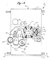
- FIGS. 1 through 7 there is shown a machine A for handling filters F of the type used in nuclear power generating stations for the purpose of filtering radioactive particles from the various water systems as generally described above.
- the machine A is adapted to receive a drum D in which a spent filter F' is to be loaded for disposal, and to travel with the drum D to a predetermined position adjacent a filter pit 17 containing the filter F' to be removed.
- the drum D has been partially filled (or lined) with cement to form a shielded cavity within of a size to receive a spent filter F'.
- the machine A is adapted to remove and replace a drum shield plug or closure plug P from the drum D and a shield plug 19 from the top of the filter pit 17 and then remove the spent filter F' from the pit and place it in the prelined drum D. Then, the machine loads a new filter F into the filter pit and replaces the shield plug 19.
- the machine includes as its principal components a carriage 10 that supports a pivoting drum table 30 and a rotatable mast 40, both of which turn about the ram vertical axis.
- the mast 40 has an outwardly extending boom 45 at the top thereof and the mast and boom support a hoist mechanism 50 adapted to engage the filters F and F', as well as the closure plug P and the shield plug 19 described above.
- a filter turret 70 is mounted on the mast 40 between the carriage 10 and the boom 45, and is rotatable to place its radially extending arms into and out of vertical alignment with the path of travel of the hoist mechanism 50.
- a drum capper assembly 100 is adapted to complete the closing of the drum D after it is positioned for capping in the drum turret 70 by placing a conventional lid L and clamp ring C on the loaded drum D prior to its removal from the machine A for completion of the disposal process.
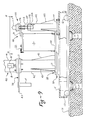
- the carriage 10 shown in best detail in FIGS. 8, 9, 13a and 13b, comprises a platform 11 formed of welded steel plate and having a rectangular configuration.
- the carriage 10 moves on four flanged wheels 12 that ride on parallel rails 13.
- the rails 13 are located parallel to one or more rows of filter pits 17 so as to carry the machine A along a path of travel sufficient to place the machine in proper relationship to any one of the filter pits from which a spent filter F' is to be removed.
- the rails 13 span both of the rows so that two filter pits can be serviced from one particular location of the carriage.
- the carriage 10 is propelled by a motor 14 that is coupled to axles that drive one pair of wheels 12.
- a pair of openings 15, 16 are formed in the forward end of the platform 11 and are located so as to be capable of alignment with adjacent filter pits 17 and 18 of two parallel rows.
- the filter pits 17 and 18 each have a stepped shield plug 19 removable by the machine A and which completes the shielding of the filter F that collects the radioactive particles.
- the turntable 20 mounteded on the platform 11 approximately in the center is a turntable 20 adapted to rotate about a central vertical axis.
- the turntable 20, best shown in FIGS. 13a and 13b, has an annular base plate 21 bolted to a bearing ring 22 by bolts 23.
- the bearing ring 22 is supported by a fixed bearing ring 24 bolted to the platform 11 by bolts 25.
- the fixed bearing ring 24 has external gear teeth 26 formed thereon that are engaged by a pinion 27 driven by either or both of two motors 28 and 28' mounted on the base plate 21 and driven through a reduction gear unit 29.
- the drum table 30 is also mounted on the platform 11 .
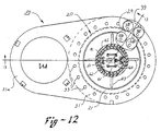
- the drum table 30, best shown in FIGS. 12, 13a and 13b, has an annular base plate 31 with a radial extension 31a with an opening that supports a drum D.
- the annular base plate 31 is bolted to a bearing ring 32 with bolts 33.
- the bearing ring 32 is supported by a fixed bearing ring 34 that is bolted to the platform 11 with bolts 35.
- the bearing ring 32 is provided with external gear teeth 36 that are engaged by a pinion 37 that turns the annular base plate 31.
- the pinion 37 is driven by either or both of two motors 38 and 38' through a reduction gear unit 39.
- the motors 38 and 38' are mounted on a bracket 38a attached to the platform 11.
- the mast 40 is mounted on the turntable assembly 20 - more specifically on the annular base plate 21 - and extends upwardly high enough to support the boom 45 at a height adequate to provide clearance for accomplishing the various movements utilized in the filter changing operation.
- the mast 40 comprises a tubular, cylindrical inner member 41 welded to the annular base plate 21 and an outer, annular, cylindrical member 42 mounted coaxial with and surrounding the inner member 41.
- the outer member 42 is also welded to the annular base plate 21, but extends upwardly only about half the height of the inner member 41.
- the member 42 is adapted to support the filter turret 70 and is braced by gussets 43 that extend radially outward and are welded to the annular base plate 31.
- the upper end of the inner member 41 has a radial flange 44 to which the boom 45 is bolted. Also, the boom 45 is braced by a gusset 46.
- the mast 40 and boom 45 turn with the turntable assembly 20 to position the hoist assembly 50 at positions over either of the filter pits 17 and 18. Accordingly, the range of motion of the turntable assembly 20 is an arc extending between the openings 15 and 16 in the platform 11. Normally, the turntable assembly 20 is not moved during a filter changing procedure once its position is initially selected.
- the boom 45 extends radially outward from the top of the mast 40 and comprises steel plates welded together to form a boxlike structure capable of enclosing portions of the hoist mechanism 50 and of providing sufficient strength to support the suspended components during the various operations performed in the filter changing process.
- the hoist mechanism 50 comprises a length of roller chain 51 that supports a grab 55 at one end and is anchored to a bracket 56 inside the mast 40 at the other end.
- the grab 55 has a collet 57 that is moved between a gripping and releasing position by a motor (not shown).
- the roller chain 51 extends upwardly from the grab 55 to an idler sprocket 58 journaled adjacent the end of the boom 45 and then rearwardly to a drive sprocket 59 mounted at the inner end of the boom 45. From the drive sprocket 59, the chain 51 extends downwardly through the cylindrical space within the mast 40 to another idler sprocket 60 journaled on a bracket 61 mounted on a counterbalance block 62 that is adapted to move vertically within the tubular inner member 41 of the mast 40. From the idler sprocket 60, the roller chain extends upwardly to the bracket 56 at the top of the mast 40.
- the drive sprocket 59 is driven through a gear box 63 by either or both of two drive motors 64 and 64'. As in the case of most of the operating equipment in the filter removal machine A, two drive motors are provided in order to have a redundancy in the event of failure of one of the motors.
- the hoist mechanism 50 is operable to raise and lower the grab 55 and articles gripped thereby through a vertical path of travel that extends from a lower limit low enough to engage a spent filter cartridge F' in a filter pit 17 to an upper limit shown in FIG. 10 sufficient to support the article engaged and suspended by the grab 55 high enough above the filter turret 70 to permit clearance between the turret and the article supported.
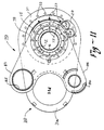
- the filter turret 70 is supported on an annular flange 71 welded to the top of the tubular, cylindrical outer member 42 of the mast 40.
- a fixed bearing ring 72 is bolted to the flange 71 with bolts 73.
- the fixed bearing ring 72 is operatively associated with a rotary bearing ring 74 that supports a turret plate 75 bolted thereto with bolts 76.
- An annular rim 77 is welded to the bottom of the plate 75 to partially enclose the operating mechanism and to provide a mount for limit switches and cams used in the control system.
- the bearing ring 74 has external gear teeth 78 that are engaged by a pinion 79 driven through a reduction gear unit 80 by either or both of two drive motors 81 and 81'.
- two motors are provided to achieve a redundancy in the event one motor fails.
- the turret plate 75 has two radially extending arms, including a filter arm 83 and a plug arm 84.
- the arms 83 and 84 extend radially outwardly and are adapted to turn between a neutral position illustrated in FIGS. 1, 3, 4, 6, 7, 8, and 11 to a position wherein one of the arms is located immediately over the filter pit to be serviced, or, in other words, directly in the vertical path of travel of the grab 55 (FIGS. 2 and 5).
- the arm 83 has a circular opening 85 adapted to receive a replacement filter cartridge F and drum shield plug P and support the cartridge by its radial rim at the upper end thereof.
- the arm 84 is provided with a receptacle 86 adapted to receive the stepped shield plug 19.
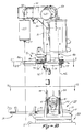
- the drum capper assembly 100 is best shown in FIGS. 9, 14, 15, 16, and 17, and is adapted to perform the function of securing a lid on the drum D once a spent filter F' has been placed in the drum and the drum shield plug P placed in position.
- the assembly is adapted to hold a drum lid L and a clamp ring C in position so that when the drum D is placed beneath the lid and clamp ring can be lowered into position and secured to the top of the drum.
- the assembly comprises a fixed base 101 mounted on the platform 11 of the carriage 10.
- the base supports an upright tubular stand or post 102 that is welded to the base 101 and braced with radially extending gussets 103.
- a mounting plate 104 is welded to the top of the post 102 and supports a pair of vertical guide pins 106 and 107 that extend upwardly from bearing blocks 108 and 109 that are welded in position in openings in the mounting plate 104.
- the capping fixture 110 Located above the vertical stand 102 is a capping fixture 110 supported for reciprocating vertical movement by the mounting plate 104.
- the capping fixture includes a main plate 111 with a pair of laterally spaced, vertical guide sleeves 113 and 114 positioned to receive the guide pins 106 and 107 so as to guide the vertical movement of the capping fixture 110.
- a support rim 120 is welded to the bottom side of the main plate 111, and has an annular plate 121 secured therein.
- the annular plate 121 supports six circumferentially spaced magnets 122 that are used to support a drum lid L to be secured to the drum D.
- the support rim 120 also has five adjustable ring retainers 123 located at circumferentially spaced locations and adapted to support the clamping ring C used to secure the lid L to the drum D.
- the rim retainers 123 are supported in brackets 124.
- a pair of cam switches 125 and 126 actuatable upon lowering of the capping fixture 110, are mounted on the cross plate 104 and are actuated by cam operators 128 secured to the main plate 111.
- the switches 125 and 126 form part of the control system for the apparatus.
- a clamping assembly 130 is located beneath the main plate 111 and is adapted to tighten the clamping ring C around the drum lid and the rim of the drum D in order to tightly seal the lid in position.
- the clamping assembly 130 includes a head 131 attached to a rod 132, the head being adapted to engage the clamp ring C.
- the rod 132 has external threads that engage the internal threads of an operating nut 134 driven from a gear unit 135 by either or both of two electrical drive motors 137 and 137'.
- the rod 132 reciprocates through a range of travel of about three inches in a direction tangential to the clamping ring.
- the machine A is located in the working space at a position to receive a prelined drum D that is transported with other equipment such as an overhead traveling bridge crane.
- the drum turret 30 is first rotated to a position wherein sufficient vertical clearance is provided to lower the drum D onto the extension 31 d.
- the clamping ring C and drum lid are removed from the drum and loaded into the capping fixture 110 of the drum capper assembly 100, as shown in FIG. 14.
- the new filter F is loaded in the filter arm 83 of the filter turret 70.
- a drum shield plug P is placed in the top of the drum D.
- the filter removal machine A is moved along the rails 13 by operating the motor 14 to a position for servicing the filter pit containing the spent filter F' to be removed. This is a predetermined position that is assumed by the carriage 10 in response to operation of suitable limit switches located, for example, on one or both of the rails 13.
- the drum table 30 When the machine is at this position, the drum table 30 is operated to bring the drum D in alignment with the vertical path of operation of the grab 55. Then, the hoist mechanism 50 is operated using the drive motors 65 and 54' to lower the grab 55 into engagement with the closure plug P in the prelined drum D. The drum shield plug P is then lifted clear of the drum, the drum table 30 is operated to move the drum from the operating path, and the filter turret 70 is operated to bring the filter arm 83 into the vertical path of travel. Then, the drum shield plug P is lowered onto the top of the filter arm 83 and the filter turret 70 is operated using the motors 81 and 81' to move the turret 70 to a neutral position clear of the vertical path of travel. The operations described above are accomplished prior to the operations illustrated in FIGS. 1 through 7.
- the hoist mechanism 50 is operated using the drive motors 64 and 64' to lower the grab 55 into engagement with the stepped shield plug 19 over the filter pit 17, as shown in dashed lines in FIG. 1, and then to raise the shield plug 19 to the full up position shown in solid lines in FIG. 1.
- the filter turret 70 is operated using the motors 81 and 81' to bring the plug arm 84 into the vertical path of travel, after which the grab 55 lowers the stepped shield plug 19 onto the plug arm 84, as shown in FIG. 2, and the turret is rotated to the neutral position.
- the filter 17 is exposed and radiation therefrom creates a hazardous condition, making accurate and reliable operation of the filter removal machine A extremely important.
- the hoist mechanism 50 is now operated to lower the grab 55 into the filter pit 17 and grasp the spent filter F', as shown in dashed lines in FIG. 3, raise it to a drip-dry position approximately two feet above the top of the filter pit 17, and hold it there for about 15 minutes. Then, the spent filter F' is raised to the full up position, as shown in solid lines in FIG. 3, and the drum table 30 is rotated to bring the drum into the vertical path, as shown in FIG. 4. Then, the spent filter F' is lowered into the prelined drum D, as shown in solid lines in FIG. 4, and the grab 55 is released and raised to its full up position.
- the drum table 30 is operated to move the drum D to a clearance position, and the filter turret 70 is operated to bring the filter arm 83 into the vertical path, after which the grab 55 is lowered, to grasp the drum shield plug P and raise it to its full up position.
- the filter turret 70 is turned to its neutral position, and the drum table 30 is operated to bring the drum D back into the vertical path, after which the hoist mechanism 50 is operated to lower the drum shield plug P into position in the drum. After the drum shield plug P is in place, the drum table 30 is operated to bring the loaded drum D into an operating position adjacent the drum capper assembly 100, as shown in FIG. 5.
- the drum capping operation and the filter changing operation can proceed; however, for present purposes, the capping operation will be described first.
- the motors 117 and 117' are operated to turn the lead screw 115 and lower the capping fixture 110 over the top of the drum D.
- This brings the lid onto the rim of the open drum and also brings the clamping ring C into position surrounding the flange of the lid and the reinforced rim of the drum.
- the clamping assembly 130 is operated to bring the clamping ring C into a tightly clamped position around the flange of the lid L, and thus secure the lid to the drum.
- the filter turret 70 is operated with the motors 81 and 81' to bring the filter arm 83 into the vertical path and the hoist mechanism 50 lowers the grab 55 into engagement with the new filter F, as shown in dashed lines in FIG. 5, and then raises it to the full up position, as shown in solid lines in FIG. 5.
- the filter turret 70 is then turned to its neutral position (FIG. 6) and the hoist mechanism 50 lowers the grab 55 and the new filter F into the filter pit 17, as shown in dashed lines in FIG. 6.
- the grab 55 is released, it is again raised to the full up position and the filter turret is operated to bring the plug arm 84, and thus the stepped shield plug 19, into the vertical path.
- the hoist mechanism 50 is then operated to lower the grab 55 into engagement with the stepped shield plug 19 and to raise the plug to the full up position shown in solid lines in FIG. 7.
- the filter turret 70 is again returned to the neutral position (FIG. 7) and the hoist mechanism 50 lowers the grab 55 and the stepped shield plug 19 onto the top of the filter pit as shown in dashed lines in FIG. 7, after which the grab 55 is released and raised to the full up position.
- the filter removal machine A is then propelled along the rails 13 to a position for unloading of the capped drum D, and, in the meantime, the drum table 30 has been operated to bring the drum D away from the drum capper assembly 100 to a position with vertical clearance to permit its removal.
- the drum D is removed using an overhead traveling gantry crane or the like, and then further processed for disposal.
Description
- This invention relates to apparatus and methods for the handling of radioactive material, and especially to the loading, removal, and replacement of filters used in nuclear power generating stations to remove radioactive impurities in the primary and secondary water systems.
- More particularly, the invention relates to an apparatus capable of control from a remote station and of performing all of the procedures required for changing a filter and for loading the spent radioactive filter in a shielded container for disposal.
- In a nuclear power plant, a coolant is circulated around the core of the reactor as a heat transfer medium that transfers the heat generated in the reactor to apparatus wherein the heat may be further transferred and/or extracted. Coolant branch circuits are provided, and they are utilized for many purposes, such as coolant volume control, coolant water chemistry control, reactivity control, etc. The reactive coolant system, its associated branch circuits (commonly known as auxiliary process systems) and their related components comprise a major portion of the fluid system of a nuclear power plant or other nuclear reactor installation.
- During operation of a nuclear reactor or other source or radioactivity, particles of foreign matter resulting from corrosion of the coolant and auxiliary process piping become entrained in the coolant and circulate therewith around the core of the reactor and through the associated cooling and process equipment and piping. As the particles flow around the source of radioactivity, they become radioactive and tend to accumulate at various locations in the piping systems and emit radioactive energy. Depending upon the shielding associated with the piping system, the radiation from the accumulated particles tends to create health hazards for personnel working in and about the radioactive fluid systems and/or associated components.
- In order to control the quantity of foreign matter flowing in the cooling and process systems, nuclear power plants and other installations are provided with filters to collect the radioactive particles for removal from the coolant and process systems. Some conventional filter housings employed to capture radioactive particles have a top hatch permitting installation and removal of a filter cartridge from above. The particle-laden cartridge is usually placed in a shielded shipping container for ultimate disposal.
- The most common filtering equipment in use today employs disposable filter cartridges that entrap the radioactive solids during the course of the filtering action. Such filter cartridges must be replaced periodically.
- The filter cartridge is usually located in a filter pit below the floor of the power plant, and covered with a shield plug forming part of the floor. Since the filter cartridges become highly radioactive during use, they are located within shielded rooms having walls with a thickness of several feet on all sides. Removal of the spent cartridge begins with removal of the shield plug, using an overhead hoist or the like, laying the shield plug aside, and exposing the filter assembly beneath the floor. The operator must remain behind a shield wall to prevent overexposure to the radiation yielded by the assembly. Once the filter pit is opened, a shielded drum or transfer cask is positioned adjacent the pit and a cartridge-grappling tool or the like is lowered in place to grasp the filter cartridge. The cartridge is then withdrawn and placed in the drum or transfer cask. Upon verification that the cartridge is in the transfer cask, the cask is removed from its position adjacent the access opening and transferred to a disposal area.
- It can be appreciated that the removal and reloading of filters is very hazardous and great care must be taken to protect the operator. The method and apparatus of the present invention resolve many of the difficulties mentioned above and afford other features and advantages heretofore not obtainable.
- It is among the objects of the invention to provide a more reliable method and apparatus for removing, storing for disposal, and replacing filter cartridges used in nuclear power stations.
- Another object is to reduce the difficulties that arise in handling radioactive filter cartridges that must be removed and disposed of in nuclear power generating stations.
- According to the present invention there is provided a remotely controlled apparatus for removing filters from and replacing filters in a filter recess characterised by a base mounted on a rigid platform and adapted to be located adjacent said recess, a hoist mechanism mounted on said base and including a mast, a boom extending outwardly from the top of said mast, a remotely operable grab for engaging loads including filters to be transported to and from said filter recess, a remotely operable lift mechanism for supporting said grab from said boom, and for raising and lowering said grab in a vertical path, a remotely operable drum table mounted on said base for rotary movement relative to said base about a vertical axis spaced from said vertical path to and from a position wherein a storage drum carried thereby is placed in said vertical path and a remotely operable turret mounted on said mast intermediate said base and said boom for movement about the vertical axis and having at least one radially extending arm adapted to be moved to and from a position aligned with said vertical path, a remote control device being provided for positioning said platform at a predetermined position relative to said filter recess whereby said vertical path of said grab may be accurately aligned with said recess.
- According to a further aspect of the invention there is provided a method for removing an old filter from and replacing a new filter in a filter recess normally covered with a shield plug, said method being controlled from a remote location using an apparatus capable of remote control, characterized by the steps of engaging and lifting said shield plug in a vertical path above and centered on said filter recess to a raised clearance position relative to said apparatus, moving a shield plug support through an arc about a vertical axis to a position beneath said shield plug, lowering said shield plug in said vertical path onto said shield plug support and releasing same, moving said shield plug support and said shield plug through an arc about said vertical axis to a position clear of said vertical path, engaging and lifting said old filter in said vertical path to a raised clearance position relative to said apparatus, moving a disposal drum through an arc about said vertical axis to a position beneath said old filter, lowering said old filter in said vertical path into said disposal drum and releasing same, moving said disposal drum through an arc about said vertical axis to a position clear of said vertical path, moving a new filter and a support therefor through an arc about said vertical axis to a position centered on said vertical path, engaging and raising said new filter in said vertical path to a raised clearance position relative to said apparatus, moving said new filter support through an arc about said vertical axis to a position clear of said vertical path, lowering said new filter in said vertical path into said filter recess and releasing same, moving said shield plug support and said shield plug through an arc about said vertical axis to a position centered in said vertical path, engaging and raising said shield plug to a raised clearance position relative to said apparatus, moving said shield plug support through an arc about said vertical axis to a position clear of said vertical path, and lowering said shield plug in said vertical path onto said filter recess and releasing same.
- In the drawings:
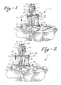
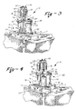
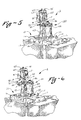
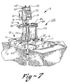
- FIGS. 1 through 7 are fragmentary, perspective views, with parts broken away, illustrating several of the sequential operating steps of the method of the invention;
- FIG. 8 is a plan view of the filter changing machine of FIGS. 1 through 7;
- FIG. 9 is a fragmentary, sectional view on an enlarged scale, taken from the line 9-9 of FIG. 8, with parts broken away for the purpose of illustration and showing the drum table turned to place a drum carried thereby at the capping station adjacent the drum capping assembly;
- FIG. 10 is a sectional view on an enlarged scale, taken on the line 10-10 of FIG. 8, with parts broken away for.the purpose of illustration;
- FIG. 11 is a sectional view on an enlarged scale, taken on the line 11-11 of FIG. 10;
- FIG. 12 is a sectional view on an enlarged scale, taken on the line 12-12 of FIG. 10;
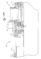
- FIGS. 13a and 13b are fragmentary, sectional views on an enlarged scale, taken on the line 13-13 of FIG. 12;
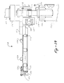
- FIG. 14 is a fragmentary, elevational view on an enlarged scale, with parts broken away and shown in section, showing the drum capper assembly and taken on the
line 1414 of FIG. 8; - FIG. 15 is a plan view of the drum capper assembly;
- FIG. 16 is a fragmentary, elevational view, with parts broken away, taken on the line 16-16 of FIG. 15; and
- FIG. 17 is a fragmentary, sectional view, taken on the line 17-17 of FIG. 16.
- Referring more particularly to the drawings, and initially to FIGS. 1 through 7, there is shown a machine A for handling filters F of the type used in nuclear power generating stations for the purpose of filtering radioactive particles from the various water systems as generally described above. The machine A is adapted to receive a drum D in which a spent filter F' is to be loaded for disposal, and to travel with the drum D to a predetermined position adjacent a
filter pit 17 containing the filter F' to be removed. The drum D has been partially filled (or lined) with cement to form a shielded cavity within of a size to receive a spent filter F'. The machine A is adapted to remove and replace a drum shield plug or closure plug P from the drum D and ashield plug 19 from the top of thefilter pit 17 and then remove the spent filter F' from the pit and place it in the prelined drum D. Then, the machine loads a new filter F into the filter pit and replaces theshield plug 19. - The machine includes as its principal components a
carriage 10 that supports a pivoting drum table 30 and arotatable mast 40, both of which turn about the ram vertical axis. Themast 40 has an outwardly extendingboom 45 at the top thereof and the mast and boom support a hoist mechanism 50 adapted to engage the filters F and F', as well as the closure plug P and theshield plug 19 described above. Afilter turret 70 is mounted on themast 40 between thecarriage 10 and theboom 45, and is rotatable to place its radially extending arms into and out of vertical alignment with the path of travel of the hoist mechanism 50. Adrum capper assembly 100 is adapted to complete the closing of the drum D after it is positioned for capping in thedrum turret 70 by placing a conventional lid L and clamp ring C on the loaded drum D prior to its removal from the machine A for completion of the disposal process. - The
carriage 10, shown in best detail in FIGS. 8, 9, 13a and 13b, comprises aplatform 11 formed of welded steel plate and having a rectangular configuration. Thecarriage 10 moves on four flangedwheels 12 that ride onparallel rails 13. Therails 13 are located parallel to one or more rows offilter pits 17 so as to carry the machine A along a path of travel sufficient to place the machine in proper relationship to any one of the filter pits from which a spent filter F' is to be removed. - In the embodiment shown, two rows of filter pits are used, and the
rails 13 span both of the rows so that two filter pits can be serviced from one particular location of the carriage. Thecarriage 10 is propelled by amotor 14 that is coupled to axles that drive one pair ofwheels 12. - A pair of
openings platform 11 and are located so as to be capable of alignment withadjacent filter pits 17 and 18 of two parallel rows. Thefilter pits 17 and 18 each have astepped shield plug 19 removable by the machine A and which completes the shielding of the filter F that collects the radioactive particles. - Mounted on the
platform 11 approximately in the center is aturntable 20 adapted to rotate about a central vertical axis. Theturntable 20, best shown in FIGS. 13a and 13b, has anannular base plate 21 bolted to abearing ring 22 bybolts 23. Thebearing ring 22 is supported by a fixed bearingring 24 bolted to theplatform 11 bybolts 25. The fixed bearingring 24 hasexternal gear teeth 26 formed thereon that are engaged by apinion 27 driven by either or both of twomotors 28 and 28' mounted on thebase plate 21 and driven through areduction gear unit 29. - Also mounted on the
platform 11 is a drum table 30 adapted to move a disposal drum D between various positions during the filter changing procedure. The drum table 30, best shown in FIGS. 12, 13a and 13b, has anannular base plate 31 with aradial extension 31a with an opening that supports a drum D. Theannular base plate 31 is bolted to abearing ring 32 withbolts 33. Thebearing ring 32 is supported by a fixed bearingring 34 that is bolted to theplatform 11 withbolts 35. Thebearing ring 32 is provided withexternal gear teeth 36 that are engaged by apinion 37 that turns theannular base plate 31. Thepinion 37 is driven by either or both of twomotors 38 and 38' through areduction gear unit 39. Themotors 38 and 38' are mounted on abracket 38a attached to theplatform 11. - The
mast 40 is mounted on the turntable assembly 20 - more specifically on the annular base plate 21 - and extends upwardly high enough to support theboom 45 at a height adequate to provide clearance for accomplishing the various movements utilized in the filter changing operation. Themast 40, best shown in FIG. 10, comprises a tubular, cylindricalinner member 41 welded to theannular base plate 21 and an outer, annular,cylindrical member 42 mounted coaxial with and surrounding theinner member 41. Theouter member 42 is also welded to theannular base plate 21, but extends upwardly only about half the height of theinner member 41. - The
member 42 is adapted to support thefilter turret 70 and is braced bygussets 43 that extend radially outward and are welded to theannular base plate 31. - The upper end of the
inner member 41 has aradial flange 44 to which theboom 45 is bolted. Also, theboom 45 is braced by agusset 46. - It will be seen that the
mast 40 andboom 45 turn with theturntable assembly 20 to position the hoist assembly 50 at positions over either of the filter pits 17 and 18. Accordingly, the range of motion of theturntable assembly 20 is an arc extending between theopenings platform 11. Normally, theturntable assembly 20 is not moved during a filter changing procedure once its position is initially selected. - The
boom 45 extends radially outward from the top of themast 40 and comprises steel plates welded together to form a boxlike structure capable of enclosing portions of the hoist mechanism 50 and of providing sufficient strength to support the suspended components during the various operations performed in the filter changing process. - The hoist mechanism 50, best shown in FIG. 10, comprises a length of
roller chain 51 that supports agrab 55 at one end and is anchored to abracket 56 inside themast 40 at the other end. Thegrab 55 has a collet 57 that is moved between a gripping and releasing position by a motor (not shown). - The
roller chain 51 extends upwardly from thegrab 55 to anidler sprocket 58 journaled adjacent the end of theboom 45 and then rearwardly to adrive sprocket 59 mounted at the inner end of theboom 45. From thedrive sprocket 59, thechain 51 extends downwardly through the cylindrical space within themast 40 to another idler sprocket 60 journaled on abracket 61 mounted on acounterbalance block 62 that is adapted to move vertically within the tubularinner member 41 of themast 40. From the idler sprocket 60, the roller chain extends upwardly to thebracket 56 at the top of themast 40. - It will be seen that the
counterbalance block 62 will move in the opposite direction from the movement of thegrab 55, but that the grab will move a distance twice the distance that thecounterbalance block 62 moves due to the arrangement of the chain and sprocket mechanism. - The
drive sprocket 59 is driven through a gear box 63 by either or both of two drive motors 64 and 64'. As in the case of most of the operating equipment in the filter removal machine A, two drive motors are provided in order to have a redundancy in the event of failure of one of the motors. - The hoist mechanism 50 is operable to raise and lower the
grab 55 and articles gripped thereby through a vertical path of travel that extends from a lower limit low enough to engage a spent filter cartridge F' in afilter pit 17 to an upper limit shown in FIG. 10 sufficient to support the article engaged and suspended by thegrab 55 high enough above thefilter turret 70 to permit clearance between the turret and the article supported. - The
filter turret 70, best shown in FIGS. 10 and 11, is supported on an annular flange 71 welded to the top of the tubular, cylindricalouter member 42 of themast 40. A fixedbearing ring 72 is bolted to the flange 71 withbolts 73. The fixedbearing ring 72 is operatively associated with arotary bearing ring 74 that supports aturret plate 75 bolted thereto with bolts 76. Anannular rim 77 is welded to the bottom of theplate 75 to partially enclose the operating mechanism and to provide a mount for limit switches and cams used in the control system. The bearingring 74 hasexternal gear teeth 78 that are engaged by a pinion 79 driven through areduction gear unit 80 by either or both of twodrive motors 81 and 81'. Here again, two motors are provided to achieve a redundancy in the event one motor fails. - The
turret plate 75 has two radially extending arms, including afilter arm 83 and aplug arm 84. Thearms arm 83 has acircular opening 85 adapted to receive a replacement filter cartridge F and drum shield plug P and support the cartridge by its radial rim at the upper end thereof. Thearm 84 is provided with areceptacle 86 adapted to receive the steppedshield plug 19. - The
drum capper assembly 100 is best shown in FIGS. 9, 14, 15, 16, and 17, and is adapted to perform the function of securing a lid on the drum D once a spent filter F' has been placed in the drum and the drum shield plug P placed in position. The assembly is adapted to hold a drum lid L and a clamp ring C in position so that when the drum D is placed beneath the lid and clamp ring can be lowered into position and secured to the top of the drum. - The assembly comprises a fixed
base 101 mounted on theplatform 11 of thecarriage 10. The base supports an upright tubular stand or post 102 that is welded to thebase 101 and braced with radially extendinggussets 103. A mountingplate 104 is welded to the top of thepost 102 and supports a pair of vertical guide pins 106 and 107 that extend upwardly from bearingblocks plate 104. - Located above the
vertical stand 102 is acapping fixture 110 supported for reciprocating vertical movement by the mountingplate 104. The capping fixture includes amain plate 111 with a pair of laterally spaced,vertical guide sleeves capping fixture 110. - Centrally mounted in the
main plate 111 is alead screw 115 with threads that engage internal threads of a nut 112 mounted on thecross plate 104. Thelead screw 115 is rotated through areduction gear unit 116 mounted on themain plate 111, thereduction gear unit 116 being driven by either or both of two drivemotors 117 and 117'. Here again, two drive motors are provided to achieve redundancy in the event one motor fails. Asupport rim 120 is welded to the bottom side of themain plate 111, and has anannular plate 121 secured therein. Theannular plate 121 supports six circumferentially spacedmagnets 122 that are used to support a drum lid L to be secured to the drum D. - The
support rim 120 also has fiveadjustable ring retainers 123 located at circumferentially spaced locations and adapted to support the clamping ring C used to secure the lid L to the drum D. Therim retainers 123 are supported inbrackets 124. - A pair of cam switches 125 and 126, actuatable upon lowering of the
capping fixture 110, are mounted on thecross plate 104 and are actuated bycam operators 128 secured to themain plate 111. Theswitches - A clamping
assembly 130 is located beneath themain plate 111 and is adapted to tighten the clamping ring C around the drum lid and the rim of the drum D in order to tightly seal the lid in position. The clampingassembly 130 includes a head 131 attached to a rod 132, the head being adapted to engage the clamp ring C. The rod 132 has external threads that engage the internal threads of an operating nut 134 driven from a gear unit 135 by either or both of twoelectrical drive motors 137 and 137'. The rod 132 reciprocates through a range of travel of about three inches in a direction tangential to the clamping ring. - The operation of the filter changing machine A of the invention is best illustrated in FIGS. 1 through 7.
- Initially, the machine A is located in the working space at a position to receive a prelined drum D that is transported with other equipment such as an overhead traveling bridge crane. The
drum turret 30 is first rotated to a position wherein sufficient vertical clearance is provided to lower the drum D onto theextension 31 d. When the drum is in position, the clamping ring C and drum lid are removed from the drum and loaded into thecapping fixture 110 of thedrum capper assembly 100, as shown in FIG. 14. At this point, the new filter F is loaded in thefilter arm 83 of thefilter turret 70. Also, a drum shield plug P is placed in the top of the drum D. - These initial steps are accomplished manually, and after completion the workmen loosen the retaining screws over the stepped
shield plug 19 for the filter pits 17 or 18 to be serviced, and then move to remote shielded locations to avoid exposure to radiation. Then, the filter removal machine A is moved along therails 13 by operating themotor 14 to a position for servicing the filter pit containing the spent filter F' to be removed. This is a predetermined position that is assumed by thecarriage 10 in response to operation of suitable limit switches located, for example, on one or both of therails 13. - When the machine is at this position, the drum table 30 is operated to bring the drum D in alignment with the vertical path of operation of the
grab 55. Then, the hoist mechanism 50 is operated using thedrive motors 65 and 54' to lower thegrab 55 into engagement with the closure plug P in the prelined drum D. The drum shield plug P is then lifted clear of the drum, the drum table 30 is operated to move the drum from the operating path, and thefilter turret 70 is operated to bring thefilter arm 83 into the vertical path of travel. Then, the drum shield plug P is lowered onto the top of thefilter arm 83 and thefilter turret 70 is operated using themotors 81 and 81' to move theturret 70 to a neutral position clear of the vertical path of travel. The operations described above are accomplished prior to the operations illustrated in FIGS. 1 through 7. - At this point, the hoist mechanism 50 is operated using the drive motors 64 and 64' to lower the
grab 55 into engagement with the steppedshield plug 19 over thefilter pit 17, as shown in dashed lines in FIG. 1, and then to raise theshield plug 19 to the full up position shown in solid lines in FIG. 1. Then, thefilter turret 70 is operated using themotors 81 and 81' to bring theplug arm 84 into the vertical path of travel, after which thegrab 55 lowers the steppedshield plug 19 onto theplug arm 84, as shown in FIG. 2, and the turret is rotated to the neutral position. - At this point, the
filter 17 is exposed and radiation therefrom creates a hazardous condition, making accurate and reliable operation of the filter removal machine A extremely important. - The hoist mechanism 50 is now operated to lower the
grab 55 into thefilter pit 17 and grasp the spent filter F', as shown in dashed lines in FIG. 3, raise it to a drip-dry position approximately two feet above the top of thefilter pit 17, and hold it there for about 15 minutes. Then, the spent filter F' is raised to the full up position, as shown in solid lines in FIG. 3, and the drum table 30 is rotated to bring the drum into the vertical path, as shown in FIG. 4. Then, the spent filter F' is lowered into the prelined drum D, as shown in solid lines in FIG. 4, and thegrab 55 is released and raised to its full up position. The drum table 30 is operated to move the drum D to a clearance position, and thefilter turret 70 is operated to bring thefilter arm 83 into the vertical path, after which thegrab 55 is lowered, to grasp the drum shield plug P and raise it to its full up position. - Next, the
filter turret 70 is turned to its neutral position, and the drum table 30 is operated to bring the drum D back into the vertical path, after which the hoist mechanism 50 is operated to lower the drum shield plug P into position in the drum. After the drum shield plug P is in place, the drum table 30 is operated to bring the loaded drum D into an operating position adjacent thedrum capper assembly 100, as shown in FIG. 5. - At this point, the drum capping operation and the filter changing operation can proceed; however, for present purposes, the capping operation will be described first. With the drum D in position beneath the
capping fixture 110, themotors 117 and 117' are operated to turn thelead screw 115 and lower thecapping fixture 110 over the top of the drum D. This brings the lid onto the rim of the open drum and also brings the clamping ring C into position surrounding the flange of the lid and the reinforced rim of the drum. Then the clampingassembly 130 is operated to bring the clamping ring C into a tightly clamped position around the flange of the lid L, and thus secure the lid to the drum. - While the drum capping operation is proceeding, the
filter turret 70 is operated with themotors 81 and 81' to bring thefilter arm 83 into the vertical path and the hoist mechanism 50 lowers thegrab 55 into engagement with the new filter F, as shown in dashed lines in FIG. 5, and then raises it to the full up position, as shown in solid lines in FIG. 5. Thefilter turret 70 is then turned to its neutral position (FIG. 6) and the hoist mechanism 50 lowers thegrab 55 and the new filter F into thefilter pit 17, as shown in dashed lines in FIG. 6. After thegrab 55 is released, it is again raised to the full up position and the filter turret is operated to bring theplug arm 84, and thus the steppedshield plug 19, into the vertical path. - The hoist mechanism 50 is then operated to lower the
grab 55 into engagement with the steppedshield plug 19 and to raise the plug to the full up position shown in solid lines in FIG. 7. Thefilter turret 70 is again returned to the neutral position (FIG. 7) and the hoist mechanism 50 lowers thegrab 55 and the steppedshield plug 19 onto the top of the filter pit as shown in dashed lines in FIG. 7, after which thegrab 55 is released and raised to the full up position. - The filter removal machine A is then propelled along the
rails 13 to a position for unloading of the capped drum D, and, in the meantime, the drum table 30 has been operated to bring the drum D away from thedrum capper assembly 100 to a position with vertical clearance to permit its removal. The drum D is removed using an overhead traveling gantry crane or the like, and then further processed for disposal.
Claims (9)
Applications Claiming Priority (2)
| Application Number | Priority Date | Filing Date | Title |
|---|---|---|---|
| US06/388,109 US4572710A (en) | 1982-06-14 | 1982-06-14 | Method and apparatus for changing filters in nuclear power stations |
| US388109 | 1982-06-14 |
Publications (2)
| Publication Number | Publication Date |
|---|---|
| EP0096891A1 EP0096891A1 (en) | 1983-12-28 |
| EP0096891B1 true EP0096891B1 (en) | 1986-09-10 |
Family
ID=23532735
Family Applications (1)
| Application Number | Title | Priority Date | Filing Date |
|---|---|---|---|
| EP83105831A Expired EP0096891B1 (en) | 1982-06-14 | 1983-06-14 | Method and apparatus for changing filters in nuclear power stations |
Country Status (5)
| Country | Link |
|---|---|
| US (1) | US4572710A (en) |
| EP (1) | EP0096891B1 (en) |
| JP (1) | JPS595997A (en) |
| CA (1) | CA1202125A (en) |
| DE (1) | DE3366049D1 (en) |
Families Citing this family (17)
| Publication number | Priority date | Publication date | Assignee | Title |
|---|---|---|---|---|
| FR2680981B1 (en) * | 1991-09-05 | 1993-11-05 | Matieres Nucleaires Cie Gle | MODULAR MIXER-DECANTER, OF THE TYPE WITH SEPARATE STAGES AND WITH MECHANICAL AGITATION. |
| US5243631A (en) * | 1992-08-19 | 1993-09-07 | General Electric Company | Control rod servicing apparatus and method |
| US5379330A (en) * | 1993-10-12 | 1995-01-03 | General Electric Company | Inner filter removal tool |
| US5347554A (en) * | 1993-10-12 | 1994-09-13 | General Electric Company | Outer filter removal tool |
| US5800703A (en) * | 1994-07-21 | 1998-09-01 | Katah Holding Ab | Water filter with hydraulically displaceable filter unit |
| US5593578A (en) * | 1994-11-15 | 1997-01-14 | B & W Nuclear Technologies | Filter adapter and disposable filter |
| US6269956B1 (en) | 1998-04-23 | 2001-08-07 | Framatome Technologies, Inc. | Disposable media filter |
| US6254774B1 (en) | 1999-10-25 | 2001-07-03 | James R. Henderson | Apparatus for radioactive particulate filtration |
| EP2027585B1 (en) * | 2006-05-23 | 2016-01-27 | MHE Technologies, Inc. | Fuel transfer system |
| US9484122B2 (en) | 2011-12-30 | 2016-11-01 | Ge-Hitachi Nuclear Energy Americas Llc | Post-accident fission product removal system and method of removing post-accident fission product |
| CN107123453A (en) * | 2017-06-08 | 2017-09-01 | 清华大学天津高端装备研究院 | A kind of replacing platform for reactor inner part |
| CN110398766B (en) * | 2019-07-09 | 2021-08-06 | 江苏中海华核环保有限公司 | Device for detecting activity level of radionuclide on surface of storage barrel |
| CN110570963B (en) * | 2019-09-10 | 2023-04-21 | 四川航天神坤科技有限公司 | Filter core snatchs transfer device |
| CN111710449A (en) * | 2020-05-26 | 2020-09-25 | 武汉第二船舶设计研究所(中国船舶重工集团公司第七一九研究所) | Device for replacing radioactive waste filter element of ocean nuclear power platform |
| CN112530619B (en) * | 2020-12-22 | 2023-09-08 | 三门核电有限公司 | Storage rack and device for storing waste filter elements in nuclear power plant |
| CN112951467B (en) * | 2021-01-29 | 2024-03-22 | 中国原子能科学研究院 | Filter core transfer device |
| CN113066597A (en) * | 2021-03-25 | 2021-07-02 | 三门核电有限公司 | Radioactive water filter core dismounting device and transport instrument thereof |
Family Cites Families (8)
| Publication number | Priority date | Publication date | Assignee | Title |
|---|---|---|---|---|
| BE634581A (en) * | 1962-07-06 | |||
| CH490725A (en) * | 1967-04-21 | 1970-05-15 | Commissariat Energie Atomique | Nuclear reactor fuel reloading facility |
| FR2139707B1 (en) * | 1971-06-01 | 1975-01-17 | Commissariat Energie Atomique | |
| FR2215295A1 (en) * | 1973-01-26 | 1974-08-23 | Reel Sa | Reactor fuel element charging machine - with simplified incore components and host of control cables outside reactor |
| DE2408261A1 (en) * | 1974-02-21 | 1975-09-11 | Krupp Gmbh | DEVICE FOR REPLACING FUEL ELEMENTS AND CONTROL STUDS IN A NUCLEAR REACTOR |
| FR2325724A1 (en) * | 1975-09-23 | 1977-04-22 | Heurtey Metallurgie | ELECTRODES CHANGE DEVICE FOR MILK REFUSION PLANT |
| JPS52113489A (en) * | 1976-03-19 | 1977-09-22 | Hitachi Ltd | Mounting/dismounting device for control rod driving device |
| US4353675A (en) * | 1977-04-18 | 1982-10-12 | Risener George W | Case and carton handling device |
-
1982
- 1982-06-14 US US06/388,109 patent/US4572710A/en not_active Expired - Lifetime
-
1983
- 1983-05-31 CA CA000429364A patent/CA1202125A/en not_active Expired
- 1983-06-14 EP EP83105831A patent/EP0096891B1/en not_active Expired
- 1983-06-14 DE DE8383105831T patent/DE3366049D1/en not_active Expired
- 1983-06-14 JP JP58106578A patent/JPS595997A/en active Granted
Also Published As
| Publication number | Publication date |
|---|---|
| JPH0244400B2 (en) | 1990-10-03 |
| US4572710A (en) | 1986-02-25 |
| DE3366049D1 (en) | 1986-10-16 |
| CA1202125A (en) | 1986-03-18 |
| EP0096891A1 (en) | 1983-12-28 |
| JPS595997A (en) | 1984-01-12 |
Similar Documents
| Publication | Publication Date | Title |
|---|---|---|
| EP0096891B1 (en) | Method and apparatus for changing filters in nuclear power stations | |
| US3765549A (en) | Apparatus and method for loading nuclear fuel into a shipping cask without immersion in a pool | |
| US5661768A (en) | Spent nuclear fuel (SNF) dry transfer system | |
| US5319686A (en) | Dry transfer of spent nuclear rods for transporation | |
| US20170162284A1 (en) | Canister transfer system with independent traveling shielded bell | |
| JP3663924B2 (en) | Method for handling reactor internal structure and apparatus used for the method | |
| JPH037276B2 (en) | ||
| US4594774A (en) | Machines for dismantling decommissioned nuclear reactors | |
| US5263062A (en) | Process and apparatus for dismantling the internal equipment of a water-cooled nuclear reactor | |
| JP2012255742A (en) | Conveyance method of radioactive structure member | |
| US3972420A (en) | Crane apparatus | |
| HU208589B (en) | Method and device for removing irradiated element of a nuclear reactor particularly tank of a pressurized water cooled nuclear reactor | |
| JP2019011988A (en) | Carrying-out device for radioactive material, carrying-in device for radioactive material, storage device for radioactive material, carrying system for radioactive material, and method thereof | |
| JPH0217498A (en) | Docking apparatus for connecting transport or storage container to working chamber exposed to radioactivity | |
| JP6360458B2 (en) | How to retrieve fuel debris | |
| GB2139804A (en) | Machines for dismantling decommissioned nuclear reactors | |
| JPS61288200A (en) | Overhaul machine for nuclear reactor, function thereof is released | |
| US4728484A (en) | Apparatus for handling control rod drive | |
| JP6032689B1 (en) | Fuel debris retrieval method | |
| JPH1054896A (en) | Method handling method and device | |
| JPS6116038B2 (en) | ||
| SK37193A3 (en) | Shielding cover | |
| JPH10115698A (en) | Canister carrying container | |
| CA1072497A (en) | Crane apparatus | |
| CA3028463A1 (en) | Methods and apparatus for handling materials for retubing of a nuclear reactor |
Legal Events
| Date | Code | Title | Description |
|---|---|---|---|
| PUAI | Public reference made under article 153(3) epc to a published international application that has entered the european phase |
Free format text: ORIGINAL CODE: 0009012 |
|
| AK | Designated contracting states |
Designated state(s): BE DE FR GB IT |
|
| 17P | Request for examination filed |
Effective date: 19840607 |
|
| GRAA | (expected) grant |
Free format text: ORIGINAL CODE: 0009210 |
|
| AK | Designated contracting states |
Kind code of ref document: B1 Designated state(s): BE DE FR GB IT |
|
| REF | Corresponds to: |
Ref document number: 3366049 Country of ref document: DE Date of ref document: 19861016 |
|
| ITF | It: translation for a ep patent filed |
Owner name: ING. C. GREGORJ S.P.A. |
|
| ET | Fr: translation filed | ||
| PLBE | No opposition filed within time limit |
Free format text: ORIGINAL CODE: 0009261 |
|
| STAA | Information on the status of an ep patent application or granted ep patent |
Free format text: STATUS: NO OPPOSITION FILED WITHIN TIME LIMIT |
|
| 26N | No opposition filed | ||
| PG25 | Lapsed in a contracting state [announced via postgrant information from national office to epo] |
Ref country code: GB Effective date: 19890614 |
|
| PG25 | Lapsed in a contracting state [announced via postgrant information from national office to epo] |
Ref country code: BE Effective date: 19890630 |
|
| BERE | Be: lapsed |
Owner name: GENERAL SIGNAL CORP. Effective date: 19890630 |
|
| GBPC | Gb: european patent ceased through non-payment of renewal fee | ||
| PG25 | Lapsed in a contracting state [announced via postgrant information from national office to epo] |
Ref country code: FR Free format text: LAPSE BECAUSE OF NON-PAYMENT OF DUE FEES Effective date: 19900228 |
|
| PG25 | Lapsed in a contracting state [announced via postgrant information from national office to epo] |
Ref country code: DE Effective date: 19900301 |
|
| REG | Reference to a national code |
Ref country code: FR Ref legal event code: ST |