KR900004740B1 - Frequency detective circuit - Google Patents
Frequency detective circuit Download PDFInfo
- Publication number
- KR900004740B1 KR900004740B1 KR1019860001743A KR860001743A KR900004740B1 KR 900004740 B1 KR900004740 B1 KR 900004740B1 KR 1019860001743 A KR1019860001743 A KR 1019860001743A KR 860001743 A KR860001743 A KR 860001743A KR 900004740 B1 KR900004740 B1 KR 900004740B1
- Authority
- KR
- South Korea
- Prior art keywords
- signal
- pulse
- frequency
- trigger
- pulse signal
- Prior art date
Links
Images


Classifications
-
- G—PHYSICS
- G01—MEASURING; TESTING
- G01R—MEASURING ELECTRIC VARIABLES; MEASURING MAGNETIC VARIABLES
- G01R23/00—Arrangements for measuring frequencies; Arrangements for analysing frequency spectra
- G01R23/02—Arrangements for measuring frequency, e.g. pulse repetition rate; Arrangements for measuring period of current or voltage
- G01R23/15—Indicating that frequency of pulses is either above or below a predetermined value or within or outside a predetermined range of values, by making use of non-linear or digital elements (indicating that pulse width is above or below a certain limit)
-
- G—PHYSICS
- G01—MEASURING; TESTING
- G01R—MEASURING ELECTRIC VARIABLES; MEASURING MAGNETIC VARIABLES
- G01R23/00—Arrangements for measuring frequencies; Arrangements for analysing frequency spectra
- G01R23/005—Circuits for comparing several input signals and for indicating the result of this comparison, e.g. equal, different, greater, smaller (comparing phase or frequency of 2 mutually independent oscillations in demodulators)
Landscapes
- Physics & Mathematics (AREA)
- General Physics & Mathematics (AREA)
- Nonlinear Science (AREA)
- Manipulation Of Pulses (AREA)
Abstract
Description
제1도는 본 발명의 한 실시예를 나타내는 회로도.1 is a circuit diagram illustrating one embodiment of the present invention.
제2a도 및 제2b도는 제1도에 나타낸 트리거펄스 발생회로의 동작을 설명하기 위한 파형도.2A and 2B are waveform diagrams for explaining the operation of the trigger pulse generation circuit shown in FIG.
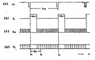
제3a-d도, 제4a-c도 및 제5a-d도는 제1도에 나타낸 회로의 동작을 설명하기 위한 동작도.3A-D, 4A-C, and 5A-D are operation diagrams for explaining the operation of the circuit shown in FIG.
* 도면의 주요부분에 대한 부호의 설명* Explanation of symbols for main parts of the drawings
1 : 주파수 판정회로 2 : 속도센서1: frequency determination circuit 2: speed sensor
6 : 트리거펄스 발생회로6: Trigger pulse generating circuit
14 : 제1리트리거레이블단안정(單安定)멀티바이브레이터14: 1st trigger label single stability multivibrator
23 : 제어회로 24 : 무안정 멀티바이브레이터23
25 : 제2리트리거레이블단안정 멀티바이브레이터25: second trigger label single stable multivibrator
P1: 제1펄스신호 P2: 제2펄스신호P 1 : first pulse signal P 2 : second pulse signal
PS : 반복펄스신호 TP : 트리거펄스PS: Repetitive pulse signal TP: Trigger pulse
본 발명은 피판정신호(被判定信號)의 주파수가 소정의 기준주파수 이상인지 아닌지를 판정하기 위한 주파수 판정회로에 관한 것이다.The present invention relates to a frequency determination circuit for determining whether or not the frequency of a signal to be judged is equal to or greater than a predetermined reference frequency.
피판정신호의 주파수가 소정의 기준주파수 이상인지 아닌지를 판별하기 위한 회로로서 피판정신호의 주파수에 따른 직류신호를 출력하고, 그 직류신호의 레벨을 소정의 기준주파수에 상응하는 기준레벨과 비교하도록한 회로는 공지되어 있다.A circuit for discriminating whether or not the frequency of the signal to be determined is equal to or greater than a predetermined reference frequency, and outputting a DC signal corresponding to the frequency of the signal to be determined, and comparing the level of the DC signal with a reference level corresponding to the predetermined reference frequency. One circuit is known.
그러나, 이 회로는 피판정신호를 그 주파수에 따른 레벨의 직류신호는 변환하기 위한 평활회로(平滑回路)의 시정수(時定數)때문에 응답성이 좋지 않다고하는 불합리가 있었다.However, this circuit has been irrational that the response is not good because of the time constant of the smoothing circuit for converting the signal to be judged from the DC signal of the level corresponding to the frequency.
이러한 불합리한 점을 해소하도록 한 주파수 판정회로로서 일본 특허공개 특개소 58-77668호 공보에 리트리거레이블단안정 멀티바이브레이터(retriggerable multivibrator) 2개를 사용한 회로가 설명되어 있다.As a frequency judging circuit for solving such an unreasonable point, a circuit using two retriever label single-stable multivibrators is described in Japanese Patent Laid-Open No. 58-77668.
이 종래의 회로는 기준주파수의 대체로 반주기와 동등한 펄스폭의 제1펄스신호를 출력할 수 있는 제1리트리거레이블단안정 멀티바이브레이터와 피판정신호의 주기의 반주기보다도 긴 펄스폭의 제2펄스신호를 출력할 수 있는 제2리트리거레이블단안정 멀티바이브레이터를 지니고, 피판정신호에 의해서 제1리트리거레이블단안정 멀티바이브레이터를 트리거(trigger) 함과 동시에 제1리트리거레이블단안정 멀티바이브레이터의 출력에 의해서 제2리트리거레이블단안정 멀티바이브레이터를 트리거하도록 구성되어 있다.This conventional circuit has a first retrieval label single-stable multivibrator capable of outputting a first pulse signal having a pulse width equivalent to half a period substantially as a reference frequency, and a second pulse signal having a pulse width longer than the half period of the cycle of the signal to be judged. It has a second trigger label single-stable multivibrator capable of outputting, and triggers the first trigger label single-stable multivibrator according to the signal to be determined, and at the same time output of the first trigger label single-stable multivibrator Is configured to trigger a second trigger label single-stable multivibrator.
따라서 이 종래의 회로에서는 피판정신호의 주파수가 기준주파수보다 낮을 경우에는 제1리트리거레이블단안정 멀티바이브레이터로 부터 출력되는 펄스신호의 주기가 기준주파수의 주기보다 길게되어, 제2리트리거레이블단안정 멀티바이브레이터는 그 출력레벨이 "O"이 되기전에 제1리트리거레이블단안정 멀티바이브레이터의 출력펄스신호에 의하여 계속 트리거하게되고, 제2리트리거레이블단안정 멀티바이브레이터의 출력레벨은 연속적으로 "H"로 유지가 된다. 한편, 피판정신호의 주파수가 기준주파수보다 높을때는 제1리트리거레이블단안정 멀티바이브레이터의 출력레벨은 "H"로 유지되어지고, 따라서 제2리트리거레이블단안정 멀티바이브레이터는 트리거가 행하여지지 않기 때문에 제2트리거레이블단안정 멀티바이브레이터의 출력레벨은 "L"레벨으로 유지된다.Therefore, in this conventional circuit, when the frequency of the signal to be determined is lower than the reference frequency, the period of the pulse signal output from the first trigger label stage stable multivibrator becomes longer than the period of the reference frequency, and thus the second trigger label stage The stable multivibrator is continuously triggered by the output pulse signal of the first trigger label single-stable multivibrator before its output level becomes "O", and the output level of the second trigger label single-stable multivibrator is continuously " H "is maintained. On the other hand, when the frequency of the signal to be determined is higher than the reference frequency, the output level of the first trigger label single-stable multivibrator is maintained at "H", so that the second trigger label single-stable multivibrator does not trigger. Therefore, the output level of the second trigger label single stable multivibrator is maintained at the "L" level.
이 종래회로는 피판정신호의 주파수가 기준주파수 근방에 있을 경우에는 제2리트리거레이블단안정 멀티바이브레이터의 출력펄스의 펄스폭분 만큼의 응답지연으로 소정의 기준주파수보다 높은지, 아닌지를 판정할 수 있다.In the conventional circuit, when the frequency of the signal to be determined is near the reference frequency, it is possible to determine whether or not the reference signal is higher than a predetermined reference frequency by a response delay equal to the pulse width of the output pulse of the second retrieval label single-stable multivibrator. .
그러나, 이 회로는 제2리트리거레이블단안정 멀티바이브레이터의 출력펄스폭이 피판정신호의 주기보다 길어야하는 회로동작이 조건으로 되어있기 때문에 피판정신호의 주파수가 저하되어, 그 주기가 제2리트리거레이블단안정 멀티바이브레이터의 출력펄스의 펄스폭보다 커지면 주파수의 판정이 불가능하게되는 외에 만약 그 펄스폭을 증대시켰다 하더라도 응답지연시간이 커진다.However, this circuit is subject to a circuit operation in which the output pulse width of the second retrieval label single-stable multivibrator must be longer than the period of the signal to be judged, so that the frequency of the signal to be determined is lowered. If the trigger label is larger than the pulse width of the output pulse of the single-stable multivibrator, the determination of the frequency becomes impossible and the response delay time increases even if the pulse width is increased.
따라서 피판정신호가 에컨데 내연기관의 회전속도를 나타내는 신호인 경우 그 주파수가 대폭으로 변동하게 되어 상술한 이유에 따라 그 판정회로에는 이따금 동작불능이 발생하게 된다.Therefore, if the signal to be judged is, for example, a signal representing the rotational speed of the internal combustion engine, the frequency fluctuates significantly, and the determination circuit occasionally fails to operate in the determination circuit.
본 발명의 목적은 따라서 피판정신호의 주파수가 대폭으로 변화하여도 그 주파수가 소정의 기준주파수보다 높은지, 이닌지의 판정을 응답성이 양호하게 행할 수 있도록 한 개선된 주파수 판정회로를 제공함에 있다.It is therefore an object of the present invention to provide an improved frequency judging circuit that enables a satisfactory responsiveness to determine whether the frequency is higher than or equal to a predetermined reference frequency even if the frequency of the signal to be judged changes drastically.
본 발명의 다른 목적은 피판정신호의 주파수가 소정의 기준주파수보다 높은지, 이닌지를 판정할 수 있는 판정회로를 제공함에 있다.Another object of the present invention is to provide a determination circuit which can determine whether or not the frequency of the signal to be judged is higher than or equal to a predetermined reference frequency.
산술한 피판정신호의 주기에 따른 트리거신호를 발생하는 수단과 그 트리거신호에 의해서 트리거되고, 상술한 기준주파수의 주기에 따른 펄스폭의 제1펄스신호를 출력할 수 있는 제1리트리거레이블단안정 멀티바이브레이터와 그 제1펄스신호의 펄스폭보다 충분히 작은 주기의 반복펄스신호를 출력하는 신호발생수단과 상기의 제1펄스신호와 상기의 반복펄스신호에 응답하고, 상기의 제1펄스신호가 출력되어 있지 않은 경우에만 반복펄스신호를 출력하는 제어수단과, 그 제어수단에서 출력되는 반복펄스신호에 응답하여 트리거되어, 제1펄스신호의 펄스폭보다 넓은 펄스폭의 제2펄스신호를 출력할 수 있는 제2리트리거레이블단안정 멀티바이브레이터를 갖추어서 이루어진 점에 특징이 있다.Means for generating a trigger signal in accordance with the cycle of the arithmetic determination signal and a first trigger label stage triggered by the trigger signal and capable of outputting a first pulse signal having a pulse width in accordance with the cycle of the reference frequency described above. A signal generating means for outputting a stable multivibrator and a repetitive pulse signal having a period sufficiently smaller than the pulse width of the first pulse signal, the first pulse signal and the repetitive pulse signal in response to the first pulse signal A control means for outputting a repetitive pulse signal only when it is not output, and in response to a repetitive pulse signal output from the control means, to output a second pulse signal having a pulse width wider than the pulse width of the first pulse signal. It is characterized by having a second trigger label single-stable multivibrator.
제1리트리거레이블단안정 멀티바이브레이터는 피판정신호의 주기가 소정의 기준주기보다 긴 경우, 하나의 트리거신호가 출력되고 나서 다음의 트리거신호가 출력될때까지의 시간의 길이가 제1펄스신호의 시간폭보다도 길게되고, 따라서 제1펄스신호는 그 레벨이 "H"와 "L"와의 사이에서 반복하여 변화하는 상태가 된다.In the first trigger label single-stable multivibrator, when the period of the signal to be judged is longer than a predetermined reference period, the length of time from the output of one trigger signal to the output of the next trigger signal is equal to that of the first pulse signal. It is longer than the time width, and therefore, the first pulse signal is in a state where the level thereof changes repeatedly between " H " and " L ".
그리고 제1펄스신호가 출력되어 있지 않는 기간중에는 제2회로수단으로부터 반복펄스신호가 출력신호로서 출력하게 된다.During the period in which the first pulse signal is not output, the repetitive pulse signal is output as an output signal from the second circuit means.
그 결과 제2리트리거레이블단안정 멀티바이브레이터는 제어수단으로부터의 출력에 의해서 출력펄스신호의 펄스폭보다 짧은 시간간격에서 계속 트리거되고 따라서 제2펄스신호는 끊임없이 계속 출력되어서 그 출력의 레벨은 "H"레벨을 유지한다.As a result, the second trigger label single-stable multivibrator is continuously triggered by the output from the control means at a time interval shorter than the pulse width of the output pulse signal, so that the second pulse signal is constantly output and the level of the output is " H " "Keep the level.
그리고 이 경우 피판정신호의 주파수가 극히 낮아져 그 주기가 제2펄스신호의 펄스폭보다 커졌다고 하더라도 제1펄스신호의 출력이 멈추고 있는 기간중, 제2리트리거레이블단안정 멀티바이브레이터는 반복펄스신호에 의해서 계속 트리거하게 되어 그 결과 제2펄스신호의 레벨은 "H"레벨을 유지한다.In this case, even if the frequency of the signal to be judged is extremely low and the period is larger than the pulse width of the second pulse signal, the second trigger label single-stable multivibrator generates a repetitive pulse signal even when the output of the first pulse signal is stopped. Triggers continuously, and as a result, the level of the second pulse signal maintains the "H" level.
한편, 피판정신호의 주기가 소정의 기준주기보다 짧은 경우에는 제1리트리거레이블단안정 멀티바이브레이터는 트리거신호에 의해서 제1펄스출력의 펄스폭보다도 짧은 경우에는 제1리트리거레이블단안정 멀티바이브레이터는 트리거신호에 의해서 제1펄스출력의 펄스폭보다도 짧은 시간간격에서 계속 트리거되므로 따라서 제1펄스신호는 끊임없이 계속 출력되어 그 출력은 "H"레벨을 유지한다.On the other hand, when the period of the signal to be determined is shorter than the predetermined reference period, the first trigger trigger single-stable multivibrator is shorter than the pulse width of the first pulse output by the trigger signal. Since the trigger signal is continuously triggered at a time interval shorter than the pulse width of the first pulse output, the first pulse signal is continuously output continuously, and the output maintains the "H" level.
그런고로 제2리트리거레이블단안정 멀티바이브레이터는 전혀 트리거되지 않고, 그 출력레벨은 "L"레벨을 유지한다.Therefore, the second trigger trigger single-stable multivibrator is not triggered at all, and its output level is maintained at the "L" level.
이와같이 피판정신호의 주기가 소정의 기준주기보다 짧은지, 아닌지에 의해서 제2리트리거레이블단안정 멀티바이브레이터의 출력레벨이 "L" 또는 "H"의 어느 것인가에 유지되고, 이에 따라 주파수의 고저의 판정을 할 수 있다.In this way, the output level of the second trigger label single-stable multivibrator is maintained in either "L" or "H" depending on whether the period of the signal to be judged is shorter than or equal to the predetermined reference period. Can be judged.
이 경우에 제1펄스신호의 레벨이 "L"가 되었을 경우에는 반복펄스신호에 의해서 제2리트리거레이블단안정 멀티바이브레이터를 계속 트리거하여 제2펄스신호의 레벨을 "H"레벨로 유지하므로 제2리트리거레이블단안정 멀티바이브레이터의 시정수를 길게할 필요가 없다.In this case, when the level of the first pulse signal becomes "L", since the second trigger label single-stable multivibrator is continuously triggered by the repetitive pulse signal, the level of the second pulse signal is maintained at the "H" level. 2Retrigger Label Single Stabilization It is not necessary to lengthen the time constant of the multivibrator.
따라서 피판정신호의 주파수가 광범위하게 변화하는 경우라 할지라도 제2펄스신호의 펄스폭은 제1펄스신호의 펄스폭보다도 약간 길게 설정하는 것으로서 족하므로 주파수가 광범위하게 변화하는 신호라도 극히 응답성이 좋게 주파수의 고저판별을 할 수 있다.Therefore, even if the frequency of the signal to be determined varies widely, the pulse width of the second pulse signal should be set slightly longer than the pulse width of the first pulse signal. Good frequency discrimination is possible.
이하 도면에 따라 본 발명을 설명코져 한다.Hereinafter, the present invention will be described with reference to the drawings.
제1도에는 본 발명에 의한 주파수 판정회로의 한 실시예를 나타내는 회로도를 나타내고 있다.1 is a circuit diagram showing one embodiment of the frequency determination circuit according to the present invention.
이 주파수 판정회로(1)는 내연기관(도면에 없음)의 회전속도를 검출하기 위한 속도센서(2)에 의하여 발생된 출력신호(S1)에 응답하고, 출력신호(S1)의 주파수가 소정의 기준주파수보다도 더 큰지 아닌지의 판정을 하는 회로이다.This frequency judging circuit 1 responds to the output signal S 1 generated by the speed sensor 2 for detecting the rotational speed of the internal combustion engine (not shown), and the frequency of the output signal S 1 is increased. It is a circuit which determines whether or not it is larger than a predetermined reference frequency.
속도센서(2)는 엔진의 크랭크축(3)에 장착된 펄서(pulser)(4)와 동 펄스에 대향하여 배치된 전자픽업코일(電磁 pick up coil)(5)으로 이루어진 공지의 것으로서, 전자픽업코일(5)에서 출력되는 출력신호(S1)의 파형은 제2도(a)에 나타낸 바와같이 교류신호로 되어 있다.The speed sensor 2 is a known one consisting of a pulser 4 mounted on the
출력신호(S1)에 따라 인접하는 양음 피이크(陽陰 peak) 사이에 제로원점(Zero cross point)의 타이밍 t1, t2, t3…을 나타내는 펄스신호를 얻기 위하여 출력신호(S1)는 트리거펄스 발생회로(6)에 입력되어 있다.The timing t 1 , t 2 , t 3 ... Of the zero cross point between adjacent positive peaks according to the output signal S 1 . The output signal S 1 is input to the trigger
트리거펄스 발생회로(6)는 출력신호(S1)를 정류하기 위한 다이오우드(7)와 트랜지스터(8)를 포함하고, 다이오우드(7)에 의해서 정류된 신호를 포화증폭하기 위한 포화증폭회로(9)로서 이루어지고 있다. 여기서 (10) 내지 (12)는 저항기, (13)은 콘덴서이다. 따라서, 트랜지스터(8)의 콜렉터(collector)로부터의 제2b도에 나타낸 트리거펄스(TP)가 출력되고, 트리거펄스(TP)는 제1리트리거레이블단안정 멀티바이브레이터(14)에 입력되어 있다.The trigger
제1리트리거레이블단안정 멀티바이브레이터(14)에는 그 Q 단자로부터 출력되는 제1펄스신호(P1)의 펄스폭을 설정하기 위한 조정용 저항기(15) 및 조정용 콘덴서(16)가 접속되어 있고, 트리거펄스(TP)는 그 AIN입력에 인가되어 있다.An adjustment resistor 15 and an
또, 한편의 BIN입력은 그 CD 단자에 접속됨과 동시에 저항기(17)를 게재하여 전원라인(18)에 접속되어 있고, 전원라인(18)은 스위치(19)를 게재하여 -극이 접지되어 있는 전지(20)의 +극에 접속되어 있다. 이 접속에 의해서 제1리트리거레이블단안정 멀티바이브레이터(14)는 트리거펄스(TP)의 발생에 응답하여 트리거되고, 그 Q 단자의 레벨이 "L"에서 "H"로 변화되어져서 펄스폭(W1)의 제1펄스신호(P1)가 출력된다.On the other hand, the B IN input is connected to the CD terminal and at the same time is connected to the power supply line 18 by placing a resistor 17, and the power supply line 18 is provided with a switch 19 and the -pole is grounded. The positive electrode of the
제1펄스신호(P1)는 저항기(21)와 트랜지스터(22)로서 이루어지는 제어회로(23)에 입력되어 있다.The first pulse signal P 1 is input to the control circuit 23 composed of the resistor 21 and the transistor 22.
제어회로(23)는 비안정 멀티바이브레이터(24)로부터의 반복펄스신호(PS)가 입력되어 있는 제2리트리거레이블단안정 멀티바이브레이터(25)의 AIN입력단자에 설치되어 있고, 제1펄스신호(P1)의 레벨이 "L"가 되었을 때만 트랜지스터(22)는 OFF가 되고, 반복펄스신호(PS)가 AIN입력단자간에 공급되는 구성으로 되어 있다.The control circuit 23 is provided at the A IN input terminal of the second trigger label single-
또한 비안정 멀티바이브레이터(24)는 인버어터(Invertor)(26)(27)(28), 저항기(29)(30)(31) 및 콘덴서(31)로서 이루어지는 공지의 회로이므로 그 상세한 것에 대한 설명은 생략하나, 그 반복펄스신호(PS)의 주기는 제1펄스신호(P1)의 펄스폭(W1)의 시간보다도 충분히 작게되도록 조정되어 있다.In addition, since the
제2리트리거레이블단안정 멀티바이브레이터(25)는 전술한 제1리트리거레이블단안정 멀티바이브레이터(14)와 동일한 구성이나, 조정용 저항기(33)와 조정용 콘덴서(34)에 의해 트리거되었을 대에 그 Q 출력단자로부터 출력되는 제2펄스신호(P2)의 펄스폭(W2)이 제1펄스신호(P1)의 펄스폭(W1)보다 약간 넓어지도록 조정되어 있는 점만이 다르다.The second trigger label single-
다음에 제3도 내지 제5도를 참조하면서 제1도에 표시한 주파수 판정회로(1)의 동작에 대해서 설명한다.Next, the operation of the frequency determination circuit 1 shown in FIG. 1 will be described with reference to FIGS. 3 to 5.
우선, 피판정신호인 출력신호(S1)의 주파수가 기준주파수보다 낮은 경우에 대해서 제3도에 따라 설명한다.First, the case where the frequency of the output signal S 1, which is the signal to be judged, is lower than the reference frequency will be described with reference to FIG.
이 경우에는 제3a도에 표시한 트리거펄스(TP)의 주기 TTP는 제1펄스신호(P1)의 펄스폭(W1)보다도 길게되어 있으므로 트리거펄스(TP)의 각 펄스의 발생에 있어서 제1리트리거레이블단안정 멀티바이브레이터(14)로부터 출력되는 제1펄스신호(P1)의 레벨은 트리거펄스(TP)의 다음 발생타이밍전에 "L"레벨이 되고, 제3b도와 같이 레벨이 변환한다.In this case, since the period T TP of the trigger pulse TP shown in FIG. 3A is longer than the pulse width W 1 of the first pulse signal P 1 , in the generation of each pulse of the trigger pulse TP, The level of the first pulse signal P 1 output from the first trigger label single-
제어회로(23)는 제1펄스신호(P1)에 응답하여 그 레벨이 "L"레벨의 경우에만 반복펄스신호(PS)를 제2리트리거레이블단안정 멀티바이브레이터(25)의 AIN입력단자에 공급하므로 AIN입력단자로의 입력신호 SIN의 파형은 제3c도에 표시한 바와같이 된다. 그 결과 제2리트리거레이블단안정 멀티바이브레이터(25)는 제3c도에 표시되는 입력신호 SIN의 각 발생타이밍에 있어서 트리거되고, 트리거된 시점에서 W2의 사이 그 Q 출력단자의 레벨을 "H"로 하도록 작동한다.The control circuit 23 inputs the repetitive pulse signal PS to the A IN input of the second trigger label single-
그런데 제2펄스신호(P2)의 펄스폭(W2)은 펄스폭(W1)보다 약간 길게 되도록 설정되어 있으므로 만약 반복펄스신호(PS)가 출력되어 있지 않으면, 시각 t=ta에 있어서 제1리트리거레이블단안정 멀티바이브레이터(14)가 트리거되므로서 출력된 제1펄스신호(P1)의 발생에 의해서 트리거된 제2리트리거레이블단안정 멀티바이브레이터(25)로부터의 제2펄스신호(P2)는 t=tb에 있어서, "L"레벨이 되고, 제1펄스신호(P1)의 다음발생시점 tc까지의 사이 그 상태를 유지하게 된다.However, since the pulse width W 2 of the second pulse signal P 2 is set to be slightly longer than the pulse width W 1 , if the repetitive pulse signal PS is not outputted, at the time t = ta, The second pulse signal from the second trigger label single-
그러나, 제1펄스신호(P1)의 레벨이 "L"의 사이 주기의 짧은 반복펄스신호(PS)가 출력되므로 그것에 의해 제2리트리거레이블단안정 멀티바이브레이터(25)가 리트리거되어 제2펄스신호(P2)의 레벨을 "H"로 유지할 수가 있다.However, since the short repetitive pulse signal PS of the period between which the level of the first pulse signal P 1 is "L" is output, the second trigger label single-
그런고로 펄스폭(W1)는 펄스폭(S1)보다 길게하는 것만으로서 끝나는 것이다.Therefore, the pulse width W 1 ends simply by making it longer than the pulse width S 1 .
다음에 제4도를 참고하여, 출력신호(S1)의 주파수가 기준주파수보다 높은 경우에 대하여 설명한다.Next, a case in which the frequency of the output signal S 1 is higher than the reference frequency will be described with reference to FIG. 4.
이 경우에는 트리거펄스(TP)의 주기 TTP는 제1펄스신호(P1)의 펄스폭(W1)보다도 짧게 되므로 제1리트리거레이블단안정 멀티바이브레이터(14)는 일단 트리거되면서 제1펄스신호(P1)의 레벨이 "L"로 되돌아오기전에 다시 트리거되기 때문에 제4b도에 표시된 바와같이 레벨은 "H'로 된채 있게 된다.In this case, since the period T TP of the trigger pulse TP is shorter than the pulse width W 1 of the first pulse signal P 1 , the first trigger trigger single-
따라서, 반복펄스신호(PS)는 출력되지 않고, 제2리트리거레이블단안정 멀티바이브레이터(25)는 트리거되지 않으므로서 제2출력신호(P2)의 레벨은 "L"로 된채 있게된다(제4도(c)).Therefore, the repetitive pulse signal PS is not output, and the second trigger trigger single-
다음에 제5도를 참조하여 출력신호(S1)의 주파수가 기준주파수보다 낮은 주파수에서 높은 주파수로 변화하였을 경우의 동작에 대해서 설명한다.Next, an operation when the frequency of the output signal S 1 changes from a frequency lower than a reference frequency to a high frequency will be described with reference to FIG.
엔진의 속도가 서서히 증대하여, 제5a도에 나타낸 트리거펄스신호(TP1)의 반복주기(TP)가 시간의 경과와 더불어 감소하고, t=td근방에 있어서 출력신호(S1)의 주파수가 소정의 기준주파수에 일치하게 된다.The engine speed gradually increases, and the repetition period TP of the trigger pulse signal TP 1 shown in FIG. 5A decreases with time, and the frequency of the output signal S 1 near t = t d. Becomes equal to a predetermined reference frequency.
따라서 t<td의 기간의 동작은 제3도에서 설명한 그대로이다.Therefore, the operation of the period t <t d is as described in FIG.
t=td에 있어서 제1펄스신호(P1)의 레벨이 "L"에서 "H"로 변화되고(제5b도), 이것에 의해서 제2리트리거레이블단안정 멀티바이브레이터(25)가 리트리거된다.At t = t d , the level of the first pulse signal P 1 changes from "L" to "H" (figure 5b), whereby the second trigger label single-
t>td에 있어서는 출력신호(S1)의 주파수가 기준주파수보다도 높아지므로, 제1펄스신호(P1)의 레벨이 "L"로 되돌아가기전에 t=te에 있어서 생기는 리트리거펄스(TP)의 발생에 의해 제1리트리거레이블단안정 멀티바이브레이터(14)가 리트리거되어 제1펄스신호(P1)의 레벨은 "L"레벨이 됨이 없이 "H"레벨상태가 유지된다.In t> t d , since the frequency of the output signal S 1 is higher than the reference frequency, the retrigger pulse generated at t = t e before the level of the first pulse signal P 1 returns to " L " By the generation of TP, the first trigger label single-
이 상태는 제4도와 관련하여 설명한 것과 같다.This state is as described in connection with FIG.
따라서, t=td이후에 있어서는 제2리트리거레이블단안정 멀티바이브레이터(25)는 트리거되지 않고, 따라서 td보다 시간(W2)이 경과한 시각 tf에 있어서 제2펄스신호(P2)의 레벨이 "L"가 되고, 이후 이 "L"레벨의 상태를 유지하게 된다.Therefore, t = In t d after the second re-trigger label
즉, 시각 td에 있어서 출력신호(S1)의 주파수는 소정의 기준주파수보다 높아지면 이로부터 시간(W2)경과후에 제2펄스신호(P2)의 레벨이 "L"가 되고, 출력신호(S1)의 주파수가 소정의 기준주파수보다 높아졌음을 판정할 수 있다.That is, when the frequency of the output signal S 1 becomes higher than the predetermined reference frequency at time t d , the level of the second pulse signal P 2 becomes "L" after the time W 2 elapses therefrom. It can be determined that the frequency of the signal S 1 is higher than the predetermined reference frequency.
이 시간폭(W2)은 상술한 설명에서 알 수 있는 바와같이 펄스폭(W1)보다도 약간 큰 값으로 설정해져 있고, 엄밀하게 말하면, 펄스폭(W1)에 반복펄스신호(PS)의 일주기의 시간폭을 더한 것보다 크면 충분하다.This time width W 2 is set to a value slightly larger than the pulse width W 1 , as can be seen from the above description, and, strictly speaking, the pulse width W 1 is applied to the repetitive pulse signal PS. It is sufficient if it is larger than the time period of the daily cycle.
이와같이 피판정신호인 출력신호(S1)의 주파수가 대폭으로 변화하여도 주파수의 고저의 판정을 확실하게 행할 수가 있고 또한 그 판정을 위한 응답시간은 W2이며, 종래에 비교해서 응답시간이 대폭으로 단축된다.In this way, even if the frequency of the output signal S 1, which is the signal to be judged, changes significantly, the determination of the high and low frequency can be reliably performed, and the response time for the determination is W 2 . It is shortened.
따라서, 내연기관의 회전속도를 표시하는 신호와 같이 그 주파수가 대폭으로 변화하는 신호에 대하여서도 잘못된 동작의 걱정이 없이 응답성이 좋게 작동하는 회로를 실현할 수가 있다.Therefore, a circuit can be realized that works well in response to a signal whose frequency changes drastically, such as a signal indicating the rotational speed of the internal combustion engine, without worrying about incorrect operation.
또한 본 발명에 의한 주파수 판정회로는 실시예에서 나타낸 용도에 한정되는 것은 아니며, 주파수가 소정의 기준주파수보다 높은지 아닌지를 판정하기 위한 여러가지의 용도에 이용됨은 물론인 것이다.In addition, the frequency determining circuit according to the present invention is not limited to the use shown in the embodiment, and is of course used for various uses for determining whether the frequency is higher than a predetermined reference frequency.
본 발명에 의하면 상술한 바와같이 피판정신호의 주파수가 대폭으로 변화하여도 잘못된 동작을 일으키지 않고, 그 주파수가 소정의 기준주파수보다 높은지 아닌지를 확실하게 판정할 수가 있고, 아울러 그 판정에 요하는 시간도 짧게 할 수 있는 고성능의 주파수 판정회로를 제공할 수가 있다.According to the present invention, as described above, even if the frequency of the signal to be judged changes drastically, it is possible to reliably determine whether or not the frequency is higher than a predetermined reference frequency without causing an erroneous operation, and at the same time the time required for the determination. It is possible to provide a high performance frequency determination circuit which can be shortened.
Claims (1)
Applications Claiming Priority (3)
| Application Number | Priority Date | Filing Date | Title |
|---|---|---|---|
| JP85-47414 | 1985-03-12 | ||
| JP60047414A JPS61207970A (en) | 1985-03-12 | 1985-03-12 | Frequency deciding circuit |
| JP47414 | 1985-03-12 |
Publications (2)
| Publication Number | Publication Date |
|---|---|
| KR860007550A KR860007550A (en) | 1986-10-13 |
| KR900004740B1 true KR900004740B1 (en) | 1990-07-05 |
Family
ID=12774482
Family Applications (1)
| Application Number | Title | Priority Date | Filing Date |
|---|---|---|---|
| KR1019860001743A KR900004740B1 (en) | 1985-03-12 | 1986-03-11 | Frequency detective circuit |
Country Status (4)
| Country | Link |
|---|---|
| US (1) | US4763025A (en) |
| JP (1) | JPS61207970A (en) |
| KR (1) | KR900004740B1 (en) |
| GB (1) | GB2188808B (en) |
Families Citing this family (4)
| Publication number | Priority date | Publication date | Assignee | Title |
|---|---|---|---|---|
| WO1991010176A1 (en) * | 1989-12-27 | 1991-07-11 | Kabushiki Kaisha Komatsu Seisakusho | Device for preventing erroneous operation when the clock is interrupted in a controller |
| WO2000066293A1 (en) * | 1999-04-28 | 2000-11-09 | Sumitomo Metal Industries, Ltd. | Molten metal surface level control in mold in continuous casting |
| JP2001036400A (en) | 1999-07-23 | 2001-02-09 | Oki Electric Ind Co Ltd | Cascade-connected type inverted circuit and limiting amplifier |
| TWI489245B (en) * | 2012-12-04 | 2015-06-21 | Univ Nat Cheng Kung | Pulse-based in-situ timing circuit system with function of predicting timing error caused from process and environment variations |
Family Cites Families (2)
| Publication number | Priority date | Publication date | Assignee | Title |
|---|---|---|---|---|
| CH484565A (en) * | 1967-12-20 | 1970-01-15 | Bosch Gmbh Robert | Up-down counting arrangement |
| GB1599459A (en) * | 1978-05-30 | 1981-10-07 | Marconi Co Ltd | Detection of narrow pulses |
-
1985
- 1985-03-12 JP JP60047414A patent/JPS61207970A/en active Granted
-
1986
- 1986-03-10 US US06/837,754 patent/US4763025A/en not_active Expired - Fee Related
- 1986-03-11 KR KR1019860001743A patent/KR900004740B1/en not_active IP Right Cessation
- 1986-04-02 GB GB8608093A patent/GB2188808B/en not_active Expired
Also Published As
| Publication number | Publication date |
|---|---|
| GB8608093D0 (en) | 1986-05-08 |
| GB2188808B (en) | 1989-12-06 |
| GB2188808A (en) | 1987-10-07 |
| KR860007550A (en) | 1986-10-13 |
| US4763025A (en) | 1988-08-09 |
| JPS61207970A (en) | 1986-09-16 |
| JPH0453387B2 (en) | 1992-08-26 |
Similar Documents
| Publication | Publication Date | Title |
|---|---|---|
| KR900004740B1 (en) | Frequency detective circuit | |
| JPS60169740A (en) | Smoke detector | |
| KR930000668B1 (en) | Iginition monitoring circuit for an ignition system | |
| US4250450A (en) | Detection of engine speed in response to ignition operation | |
| JPH0332113Y2 (en) | ||
| US4351282A (en) | Ignition timing control system for internal combustion engine | |
| JPH0566235A (en) | Peak holding circuit, peak detecting circuit and peak-position detecting circuit | |
| JPH0664120B2 (en) | Method for measuring dv / dt tolerance of thyristor | |
| JP2002156393A (en) | Battery voltage measuring circuit | |
| JPH028146B2 (en) | ||
| JPH0749421Y2 (en) | Peak detection circuit | |
| JPS6151138B2 (en) | ||
| KR0120585B1 (en) | Sp/lp mode detection circuit | |
| SU1583994A1 (en) | Device for measuring pressure in vacuum electronic device | |
| JPH0831783B2 (en) | Wave shaping circuit | |
| SU1522120A1 (en) | Converter of capacity and resistance to time interval | |
| SU1379641A1 (en) | Piezoelectric device for checking vibration | |
| JP3325142B2 (en) | Combustion state detection method using ion current | |
| KR880002867Y1 (en) | Mono-stable multivibrator | |
| SU1652805A1 (en) | Non-contact position pickup | |
| SU868995A1 (en) | Sawtooth voltage generator | |
| SU1566312A1 (en) | Device for monitoring insulation resistance of electric circuits | |
| JPH0339738Y2 (en) | ||
| JPH0524182Y2 (en) | ||
| JPH08240172A (en) | Combusting condition detecting device with ion current |
Legal Events
| Date | Code | Title | Description |
|---|---|---|---|
| A201 | Request for examination | ||
| E902 | Notification of reason for refusal | ||
| G160 | Decision to publish patent application | ||
| E701 | Decision to grant or registration of patent right | ||
| GRNT | Written decision to grant | ||
| FPAY | Annual fee payment |
Payment date: 19970704 Year of fee payment: 8 |
|
| LAPS | Lapse due to unpaid annual fee |