KR900003970B1 - Method of controlling elimination of roll eccentricity in rolling mill and device for carrying out the method - Google Patents
Method of controlling elimination of roll eccentricity in rolling mill and device for carrying out the method Download PDFInfo
- Publication number
- KR900003970B1 KR900003970B1 KR1019870004302A KR870004302A KR900003970B1 KR 900003970 B1 KR900003970 B1 KR 900003970B1 KR 1019870004302 A KR1019870004302 A KR 1019870004302A KR 870004302 A KR870004302 A KR 870004302A KR 900003970 B1 KR900003970 B1 KR 900003970B1
- Authority
- KR
- South Korea
- Prior art keywords
- roll
- eccentricity
- rotation angle
- backup
- gap
- Prior art date
Links
Images


Classifications
-
- B—PERFORMING OPERATIONS; TRANSPORTING
- B21—MECHANICAL METAL-WORKING WITHOUT ESSENTIALLY REMOVING MATERIAL; PUNCHING METAL
- B21B—ROLLING OF METAL
- B21B37/00—Control devices or methods specially adapted for metal-rolling mills or the work produced thereby
-
- B—PERFORMING OPERATIONS; TRANSPORTING
- B21—MECHANICAL METAL-WORKING WITHOUT ESSENTIALLY REMOVING MATERIAL; PUNCHING METAL
- B21B—ROLLING OF METAL
- B21B37/00—Control devices or methods specially adapted for metal-rolling mills or the work produced thereby
- B21B37/58—Roll-force control; Roll-gap control
- B21B37/66—Roll eccentricity compensation systems
Abstract
Description
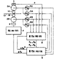
제 1 도는 본 발명의 양호한 실시예의 블록도.1 is a block diagram of a preferred embodiment of the present invention.
제 2 도는 제 1 도중 롤 편심 제거 제어계의 블록도.2 is a block diagram of a roll eccentricity removal control system during a first view.
제 3 도 및 제 4 도는 롤 편심 검출 동작을 설명하기 위한 파형도.3 and 4 are waveform diagrams for explaining the roll eccentricity detection operation.
제 5 도는 본 발명에 따른 롤 편심 검출 과정의 흐름도.5 is a flowchart of a roll eccentricity detection process according to the present invention.
제 6 도는 본 발명에 따른 롤 편심 재생 과정의 흐름도.6 is a flowchart of a roll eccentric regeneration process according to the present invention.
* 도면의 주요부분에 대한 부호의 설명* Explanation of symbols for main parts of the drawings
1A, 1B : 위킹 롤 2A, 2B : 백업롤1A, 1B:
3 : 하중검출기 4A, 4B : 마크 펄스 발생기3:
5A, 5B : 샘플링 펄스발생기 6 : 유압실린더5A, 5B: Sampling pulse generator 6: Hydraulic cylinder
7 : 유압제어장치 8 : 롤 편심 검출회로7: hydraulic control device 8: roll eccentric detection circuit
9 : 롤 편심 재생회로 10 : 압연재9 roll
본 발명은 백업롤을 갖는 다중 압연기를 롤 편심 제거 제어방법 및 장치에 관한 것이다.The present invention relates to a roll eccentric elimination control method and apparatus for a multiple mill having a backup roll.
강판들을 압연하는 압연기에 있어서, 백업롤(backup roll)의 편심에 의한 롤 갭(roll gap)의 변동에 따라 유발되는 압연재의 판두께 변동 및 그 장력변동은, 제품의 품질을 저하시킬뿐만 아니라 압연공정을 불안정하게하는 요인이 된다.In the rolling mill for rolling steel sheets, the plate thickness variation and the tension variation of the rolled material caused by the variation of the roll gap due to the eccentricity of the backup roll not only degrades the product quality but also It becomes a factor to destabilize the rolling process.
특히, 최근들어 응답속도가 빠른 유압장치를 구비한 압연기가 사용되고 있는데, 이 유압장치의 고속응답 특성을 최대로 활용하여 판두께의 정밀도가 우수한 제품을 생산하기 위해서는, 백업롤의 편심을 반드시 제거하지 않으면 안된다.In particular, recently, rolling mills equipped with hydraulic devices with fast response speeds have been used. In order to produce products with excellent plate thickness precision by utilizing the high-speed response characteristics of these hydraulic devices, the eccentricity of the backup rolls is not necessarily eliminated. You must.
한쌍의 워킹롤(working roll)과 한쌍의 백업롤로 구성되는 4중 압연기에 대해 이하에 설명한다. 일반적으로, 롤 편심은 기본파 성분 이외에도 고조파 성분을 포함하지만, 설명의 편의상 이하에서는 각 백업롤의 1회전을 1주기로 하는 기본파 성분만을 생각하기로 한다.A quadruple rolling machine composed of a pair of working rolls and a pair of backup rolls will be described below. In general, roll eccentricity includes harmonic components in addition to the fundamental wave components, but for convenience of description, only the fundamental wave components having one rotation of each backup roll as one cycle will be considered below.
상, 하 백업롤의 편심을 각각 △SA, △SB로하면, 합성 롤 편심 △SE은 다음의 (1)식으로 표시된다. 즉,When the eccentricity of the upper and lower back-up rolls is ΔS A , ΔS B , respectively, the synthetic roll eccentric ΔS E is represented by the following formula (1). In other words,
△SE=△SA+△SB……………………………………………………………(1)ΔS E = ΔS A + ΔS B. … … … … … … … … … … … … … … … … … … … … … … (One)
△SA=XA·sin(θA+øA) ……………………………………………………(2) △ S A = X A · sin (θ A + ø A) ... … … … … … … … … … … … … … … … … … … … (2)
△SB=XB·sin(θB+øB) ……………………………………………………(3) △ S B = X B · sin (θ B + ø B) ... … … … … … … … … … … … … … … … … … … … (3)
여기서, XA: 상 백업롤의 편심량Where X A : Eccentricity of phase backup roll
XB: 하 백업롤의 편심량X B : Eccentricity of lower backup roll
θA: 하 백업롤의 회전각θ A : Rotation angle of lower backup roll
θB: 하 백업롤의 회전각θ B : Rotation angle of lower backup roll
øA: θA=0일때, 상 백업롤의 위상ø A : Phase of phase backup roll when θ A = 0
øB: θB=0일때, 하 백업롤의 위상ø B : Phase of lower backup roll when θ B = 0
일반적으로, 상, 하 백업롤의 편심의 합성량 △SE을 압연하중 신호로부터 검출하여 롤 편심을 검출하도록 하고 있다.Generally, the combined amount DELTA S E of the up and down backup rolls is detected from the rolling load signal to detect the roll eccentricity.
그런데, 최근, 판 크라운(crown) 또는 판형상을 제어하기 위해서, 상, 하 워킹롤의 원주속도간에 차이를 두어 압연하는 방식이 채택되고 있다. 이 경우, 상, 하 백업롤의 편심 주파수가 서로 다르기 때문에, 상, 하 백업롤의 편심을 각각 검출하여 이들의 편심을 제거하는것이 필요하게 된다. 또한, 상, 하 워킹롤의 원주속도가 동일한 경우에도 상, 하 백업롤의 직경이 서로 다르면, 마찬가지로 상, 하 백업롤의 편심 주파수가 서로 다르게 된다.By the way, in recent years, in order to control a plate crown or plate shape, the method of rolling with the difference between the circumferential speeds of the upper and lower walking rolls is adopted. In this case, since the eccentric frequencies of the upper and lower backup rolls are different from each other, it is necessary to detect the eccentricities of the upper and lower backup rolls and to remove these eccentricities. Further, even when the upper and lower walking rolls have the same circumferential speed, if the diameters of the upper and lower backup rolls are different from each other, the eccentric frequencies of the upper and lower backup rolls are different.
상, 하 백업롤의 편심을 각각 검출하는 종래 방법으로서, 일본국 특공소 56-22281호나 일본국 특개소 60-141321호의 공보에 기재된 방식의 것이 있다. 이들의 공보에 기재되어 있는 종래의 기술은, 소위 키스롤(kiss roll)의 상태, 즉 재료를 압연하지 않은 상태에서 압연 하중을 발생시키고, 이때의 상, 하 백업롤의 회전속도와 하중신호를 이용해서 하중신호를 퓨리에 변환함으로써, 상, 하 백업롤의 편심을 각각 검출하는것이다. 이와같이하여 검출한 롤 편심량을 상, 하 백업롤의 회전각에 대응시켜서 재생하고, 롤 편심에 의한 롤 갭의 변화를 제거하는 방향으로, 롤 갭 제어장치에 갭 기준신호로서의 재생신호를 부여함으로써, 롤 편심에 의한 롤 갭의 변화를 제거하고, 그에따라 판두께의 정밀도를 향상시키고자 하는 것이다. 따라서, 소위 키스롤의 상태에서 검출한 롤 편심량과 압연중의 롤 편심량이 같을때에는, 롤 편심의 제거 제어가 고정밀도로 수행될수 있다.As a conventional method for detecting the eccentricity of the upper and lower back-up rolls, there is one of the method described in Japanese Unexamined Patent Publication No. 56-22281 or Japanese Unexamined Patent Publication No. 60-141321. The prior art described in these publications generates a rolling load in the state of a so-called kiss roll, i.e., without rolling the material, and at this time, the rotational speed and load signals of the upper and lower backup rolls are adjusted. Fourier transformation of the load signal is used to detect the eccentricity of the upper and lower backup rolls. The roll eccentricity detected in this way is reproduced in correspondence with the rotation angle of the up and down backup rolls, and a reproduction signal as a gap reference signal is applied to the roll gap control device in a direction to remove the change in the roll gap due to the roll eccentricity. It is to remove the change of the roll gap by roll eccentricity, and to improve the precision of plate | board thickness accordingly. Therefore, when the roll eccentricity detected in the state of the so-called kiss roll and the roll eccentricity during rolling are the same, removal control of the roll eccentricity can be performed with high precision.
압연하중의 크기에 따른 롤 편심량의 변화, 즉 롤 편심량의 경시 변화가 있다는 것은 주지의 사실인데, 각종의 압연조건하에서 전술한 종래 방식으로는 롤 편심을 고정밀도로 검출한다는 것이 거의 불가능하다.It is well known that there is a change in the amount of roll eccentricity according to the size of the rolling load, that is, a change in the amount of roll eccentricity with time, and it is almost impossible to detect the roll eccentricity with high accuracy by the above-described conventional method under various rolling conditions.
더우기, 압연기 입측에서 차례로 압연재를 용접하고, 압연기의 가동을 중지시키는 일없이 연속적으로 압연하는 완전 연속식 압연기에서는, 키스롤의 상태를 실현할 기회가 거의 없으므로 전술한 종래방식의 적용은 곤란하다.Moreover, in the fully continuous rolling mill which continuously welds the rolling material at the rolling mill inlet side and continuously rolls without stopping the operation of the rolling mill, there is little chance of realizing the state of the kiss roll, so the application of the conventional method described above is difficult.
본 발명은 종래기술의 문제점을 해결하고, 롤 편심 검출정밀도의 향상을 도모한, 다중 압연기의 롤 편심 검출 제거 제어방법 및 장치를 제공하는 것을 그 목적으로 한다.An object of the present invention is to provide a roll eccentric detection removal control method and apparatus for a multiple rolling mill, which solves the problems of the prior art and aims to improve the roll eccentricity detection accuracy.
본 발명은 상, 하 백업롤의 위상이 서로 다른 타이밍에서의 압연하중신호를 각 백업롤의 수 회전하는 주기동안 검출하고 ; 이렇게 얻어진 압연 하중 신호를 퓨리에 해석함으로써, 상, 하 백업롤의 편심을 각각 검출하며; 이렇게 얻어진 편심을 이용하여 롤 갭을 제어하도록 한것을 특징으로 한다.The present invention detects a rolling load signal at a timing at which phases of upper and lower backup rolls are different from each other during a period of several rotations of each backup roll; Fourier analysis of the thus obtained rolling load signal detects the eccentricity of the upper and lower backup rolls, respectively; The roll gap is controlled by using the eccentricity thus obtained.
본 발명에 따르면, 상, 하 백업롤의 편심 주파수가 서로 다른 경우에도, 압연중에 얻어진 데이타를 이용하여 상, 하 백업롤의 편심을 서로 독립적으로 검출할수 있다. 따라서, 롤 편심의 경시 변화나, 밀 정수 M 및 압연재의 소성계수 Q에 대한 오차 등에 의한 외란이 존재하더라도 고정밀도의 롤 편심 검출을 수행하여, 판두께의 정밀도를 향상시킬수 있음은 물론 압연 공정의 안정화를 달성할수 있다.According to the present invention, even when the eccentric frequencies of the upper and lower backup rolls are different, the eccentricity of the upper and lower backup rolls can be detected independently from each other using the data obtained during rolling. Therefore, even if there are disturbances due to changes in roll eccentricity over time, errors in milling constant M, and plasticity factor Q of the rolled material, high precision roll eccentricity detection can be performed to improve the accuracy of the plate thickness as well as the rolling process. Stabilization of can be achieved.
이하, 제 1 도에 도시한 실시예에 대하여 본 발명을 상세히 설명한다.EMBODIMENT OF THE INVENTION Hereinafter, this invention is demonstrated in detail about the Example shown in FIG.
제 1 도는 본 발명을 4중 압연기에 적용한 예를 도시한 것으로, 상, 하 워킹롤(1A),(1B)과 상, 하 백업롤(2A),(2B)로 구성되는 압연기에 의해 압연재(10)를 압연하고 있다. 상, 하의 백업롤(2A),(2B)에는 각 백업롤이 1회전 할때마다 하나의 마크 펄스를 발생하는 마크 펄스 발생기 PGM(4A),(4B)와, 또한 각 백업롤이 1회전 할때마다 소정수 n(예를들면, n=64)의 샘플링 펄스를 발생하는 샘플링 펄스발생기 PGS(5A),(5B)가 설치되어 있다. 이들 4대의 펄스발생기(4A),(4B) 및 (5A),(5B)의 출력펄스들은 롤 편심검출회로(8) 및 롤 편심 재생회로(9)에 각각 인가된다. 한편, 압연기에는 압연하중 P를 검출하는 하중검출기(3)가 설치되어 있고, 검출된 압연 하중신호는 롤 편심 검출회로(8)에 인가된다.FIG. 1 shows an example in which the present invention is applied to a quadruple rolling mill, and is rolled by a rolling mill composed of upper and lower working rolls 1A and 1B and upper and
롤 편심 검출회로(8)는, 후술하는 알고리즘에 따라서, 상, 하 백업롤의 편심량 XA *,XB *및 위상 øA *,øB *을 검출하여, 롤 편심 재생회로(9)에 인가한다. 롤 편심 재생회로(9)는 상, 하 백업롤(2A),(2B)의 각각의 회전각에 따라서, 상, 하 백업롤(2A),(2B)의 각각의 롤 편심 △SA *,△SB *을 재생하고, 상기 (1)식에 따라 합성 롤 편심 △SE *을 연산한후, 그것을 롤 편심 검출회로(8)로 되돌려 보냄과 동시에, 롤 갭 조작량 △SC으로서 유압 제어장치(7)로 출력한다. 유압제어장치(7)는 롤 갭 조작량 △SC에 따라 유압실린더(6)의 피스톤위치를 제어한다. 이에따라, 워킹롤(1A),(1B)간의 롤 갭이 롤 편심에 의해 변동하는 양만큼 저감되고, 압연재(10)의 판두께가 고정밀도로 제어된다.The roll
제 2 도는 제 1 도에 있어서의 롤 편심 제거 제어계의 블럭도이다. 제 2 도에 있어서, 유압 제어계(11)는 제 1 도의 유압 제어장치(7)에 입력되는 롤 갭 조작량 △SC으로부터 실제의 롤 갭이 얻어지는 점까지의 전달함수를 나타내는 블럭이다. 또, 블럭(12)은 롤 갭 변화와 압연 하중 변화와의 관계를 나타내는 블럭이고, 블럭(13)은 롤 갭 변화와 압연된 제품의 두께의 변화와의 관계를 나타내는 블럭이다. 블럭(12) 및 (13)에서, M은 밀 정수, Q는 압연재의 소성 계수이다.2 is a block diagram of the roll eccentricity removal control system in FIG. The method of
롤 편심 △SE에 의한 롤 갭의 변화에 따라 롤 편심 재생회로(9)에서 조작량 △SC이 출력되고, 롤 갭이 △SE *만큼 조작되면, 실제의 롤 갭 변화량 ε은,When the roll eccentricity △ in accordance with the change of roll gap due to the operation amount △ S E and S C output from the roll
ε=△SE-△SE *…………………………………………………………………(4)ε = DELTA S E -DELTA S E * . … … … … … … … … … … … … … … … … … … … … … … … … (4)
가 되고, 압연된 제품의 두께의 변화량 △h 및 압연하중의 변화량 △p은 각각 다음의 (5),(6)식으로 표시된다.The change amount Δh of the thickness of the rolled product and the change amount Δp of the rolling load are represented by the following formulas (5) and (6), respectively.
△h=(M/M+Q))·ε ……………………………………………………………(5)Δh = (M / M + Q))? … … … … … … … … … … … … … … … … … … … … … … (5)
△p=-((M·Q/(M+Q))·ε ……………………………………………………(6)Δp =-((M · Q / (M + Q)) · ε …………………………………………………… (6)
따라서, 롤 편심을 고정밀도로 검출하고, △SE *=△SE가 되도록 제어하면, 롤 편심에 의한 압연제품 두께의 변화 및 압연 하중 변화를 제거할수 있다.Therefore, if the roll eccentricity is detected with high accuracy and controlled so that (DELTA) S E * = (DELTA) S E , the change of the rolled product thickness and rolling load change by roll eccentricity can be eliminated.
다음에, 롤 편심을 검출하기 위한 알고리즘을 제 3 도 및 제 4 도를 이용하여 설명한다. 제 3 도 및 제 4 도에 있어서, (a)는 마크 펄스 발생기(4A)에서 출력되는 상 백업롤(2A)의 마크 펄스 ; (b)는 상 백업롤(2A)의 편심 △SA의 파형 ; (c)는 마크 펄스 발생기(4B)에서 출력되는 하 백업롤(2B)의 마크 펄스 ; (d)는 하 백업롤(2B)의 편심 △SB의 파형 ; (e)는 합성 롤 편심 △SE의 파형이다. 또, 여기에서는 상, 하 백업롤(2A),(2B)의 회전속도가 다른 경우를 나타내고 있다.Next, an algorithm for detecting roll eccentricity will be described with reference to FIGS. 3 and 4. 3 and 4, (a) represents a mark pulse of the
제 3 도에 있어서, øA는 제 3a 도의 상 백업롤의 마크 펄스에 대한 상 백업롤의 편심 △SA의 위상 ; øB는 제 3c 도의 하 백업롤의 마크 펄스에 대한 하 백업롤의 편심 △SE의 위상이고, øA및øB가 마크 펄스의 발생 타이밍에서 0이면 (θA=0,θB=0), 제 3 도의 øA및 øB는 (2)식과 (3)식에서의 øA와 øB와 각각 같다. 또, øBA1은 제1의 하 백업롤 마크 펄스 n1에 대한 상 백업롤 편심 △SA의 위상 ; øAB1은 제1의 상 백업롤 마크 펄스 m1에 대한 하 백업롤 편심 △SB의 위상이다. 마찬가치로, øBA2,øAB2는 각각 제3의 마크 펄스 m3, n3에 대한 상 백업롤 편심 △SA,△SB의 위상을 나타내고 있다. 제 3e 도에 표시한 합성 롤 편심 △SE은 상, 하 백업롤 (2A),(2B)의 회전속도가 서로 다르기 때문에, 서어지 파형으로 된다. 이 합성 롤 편심은 검출된 압연 하중에서 얻어진다.In Fig. 3,? A is the phase of the eccentric ΔS A of the image backup roll with respect to the mark pulse of the image backup roll in Fig. 3A; ø B is the phase of the eccentric ΔS E of the lower backup roll relative to the mark pulse of the lower backup roll of FIG. 3c, and if ø A and ø B are 0 at the timing of generation of the mark pulse (θ A = 0, θ B = 0) ), third-degree ø a and ø B are respectively and ø a and ø B of (2) and (3) expression. Further, BA1 ø is the phase of the back-up roll eccentricity △ S A for a back-up roll and the mark pulses n 1 of the first; AB1 is the phase of the lower backup roll eccentric ΔS B with respect to the first phase backup roll mark pulse m 1 . Similarly,? BA2 and? AB2 indicate the phases of the phase backup roll eccentric? S A and? S B with respect to the third mark pulses m 3 and n 3 , respectively. The composite roll eccentric ΔS E shown in FIG. 3E is a surge waveform because the rotation speeds of the upper and lower backup rolls 2A and 2B are different from each other. This composite roll eccentricity is obtained from the detected rolling load.
이제, 상 백업롤 마크 펄스 m1를 기준으로, 이것으로부터 제5의 상 백업롤 마크 펄스 m5까지의 4주기분의 검출 데이타(데이타-A1)중의 롤 편심 △S11을 생각하면, 이 롤 편심 △S11은Now, based on the back-up roll mark pulse 1 m, considering the roll eccentricity △ 11 S of the four cycle detection data (data -A1) of claim 5 to a back-up roll mark pulse of 5 m from the result, the roll Eccentric △ S 11 is
△S11=XA·sin(θA+øA) +XB·sin(θB+øAB1) ……………………………(7) △ S 11 = X A · sin (θ A + ø A) + X B · sin (θ B + ø AB1) ... … … … … … … … … … … (7)
으로 표시된다. 하 백업롤 마크 펄스 n1을 기준으로, 이것으로부터 제5의 하 백업롤 마크 펄스 n5까지의 4주기분의 검출데이타(데이타 -B1)중의 롤 편심 △S12은,Is displayed. Back up roll marks, based on the n pulse 1, a roll eccentricity △ 12 S of the four cycle detection data (data -B1) of the back-up roll to the fifth and the mark pulses n 5 from this,
△S12=XA·sin(θA+øBA1) +XB·sin(θB+øB) ……………………………(8) △ S 12 = X A · sin (θ A + ø BA1) + X B · sin (θ B + ø B) ... … … … … … … … … … … (8)
로 표시된다. 마찬가지로, 제3의 상 백업롤 마크 펄스 m3를 기준으로, 이것으로부터 제7의 상 백업롤 마크 펄스 m7까지의 4주기분의 검출 데이타(데이타-A2)중의 이 롤 편심 △S21은,Is displayed. Similarly, the roll eccentric ΔS 21 in the detection data (data-A2) for four cycles from this to the seventh phase backup roll mark pulse m 7 on the basis of the third phase backup roll mark pulse m 3 is
△S21=XA·sin(θA+øA) +XB·sin(θB+øAB2) ……………………………(9) △ S 21 = X A · sin (θ A + ø A) + X B · sin (θ B + ø AB2) ... … … … … … … … … … … (9)
로 표시되고, 제3의 하 백업롤의 마크 펄스 n3를 기준으로, 이것으로부터 제7의 마크 펄스 n7까지의 4주기분의 검출 데이타 (데이타-B2)중의 롤 편심 △S22은The roll eccentric ΔS 22 in the detection data (data-B2) for four cycles from this to the seventh mark pulse n 7 on the basis of the mark pulse n 3 of the third lower backup roll
△S22=XA·sin(θA+øBA2) +XB·sin(θB+øB) …………………………(10) △ S 22 = X A · sin (θ A + ø BA2) + X B · sin (θ B + ø B) ... … … … … … … … … … 10
으로 표시된다. 여기서,Is displayed. here,
øBA2=øBA2+α …………………………………………………………………(11)ø BA2 = ø BA2 + α... … … … … … … … … … … … … … … … … … … … … … … … … (11)
øBA2=øBA2+β …………………………………………………………………(12) BA2 = BA2 + β. … … … … … … … … … … … … … … … … … … … … … … … … (12)
로 하고, (11)식을 (9)식에 또한 (12)식을 (10)식에 대입하여, δ1=(△S11-△S21) 및 δ2=(△S12-△S22)를 구하면 각각 (13),(14)식으로 된다.(11) is substituted for (9) and (12) is substituted for (10), where δ 1 = (ΔS 11 −ΔS 21 ) and δ 2 = (ΔS 12 −ΔS 22 ) is obtained by the equations (13) and (14), respectively.
δ1=△S11-△S21 δ 1 = △ S 11- △ S 21
=XB·sin(θB+øAB1) -XB·sin(θB+øAB1+α) = X B · sin (θ B + ø AB1) -X B · sin (θ B + ø AB1 + α)
=2·XBsin(-α/2)·cos(θB+øAB1+α/2) ………………………………(13)= 2 X B sin (−α / 2) cos (θ B + ° AB1 + α / 2). … … … … … … … … … … … (13)
δ2=△S12-△S22 δ 2 = △ S 12- △ S 22
=XA·sin(θA+øBA1) -XA·sin(θA+øBA1)+β) = X A · sin (θ A + ø BA1) -X A · sin (θ A + ø BA1) + β)
2·XAsin(-β/2) ·cos(θA+øBA1+β/2) …………………………………(14)2 · X A sin (−β / 2) · cos (θ A + ø BA1 + β / 2). … … … … … … … … … … … … (14)
이 δ1및 δ2를 각각 퓨리에 해석하면,Fourier analysis of δ 1 and δ 2 , respectively,
δ1=X1·sin(ωt+θ1) …………………………………………………………(15)δ 1 = X 1 · sin (ωt + θ 1 ). … … … … … … … … … … … … … … … … … … … … … (15)
δ2=X2·sin(ωt+θ2) …………………………………………………………(16)δ 2 = X 2 · sin (ωt + θ 2 ). … … … … … … … … … … … … … … … … … … … … … (16)
가 얻어진다. 따라서 (13) 식과 (15) 식으로부터,Is obtained. Therefore, from (13) and (15),
XB=X1/(2·sin(-α2)) ………………………………………………………(17)X B = X 1 / (2sin (−α 2)). … … … … … … … … … … … … … … … … … … … … (17)
øB=θ1-α/2+π/2 ……………………………………………………………(18)ø B = θ 1 -α / 2 + π / 2... … … … … … … … … … … … … … … … … … … … … … … (18)
가 얻어지고, 또(14)식과 (16)식으로부터,Is obtained, and from (14) and (16),
XA=X2/(2·sin(-β/2)) ………………………………………………………(19)X A = X 2 / (2sin (-β / 2))... … … … … … … … … … … … … … … … … … … … … (19)
øA=θ2-β/2+π/2 ……………………………………………………………(20) A A = θ 2 -β / 2 + π / 2... … … … … … … … … … … … … … … … … … … … … … … 20
가 얻어진다.Is obtained.
여기서, α,β는 각각 마크 펄스 m1및 n1간의 위상과 m3및 n3간의 위상의 차이고, α는 상 백업롤(2A)에 대한 하 백업롤(2B)의 위상 변화량, β는 하 백업롤(2B)에 대한 상 백업롤(2A)의 위상 변화량을 나타낸다. 이 α,β의 값은 상, 하 백업롤(2A),(2B)의 마크 펄스와 회전속도를 검출함으로써 얻어지며, 기지의 값이다.Is the difference between the phases between the mark pulses m 1 and n 1 and the phases between m 3 and n 3 , and α is the amount of phase change of the lower backup roll 2B relative to the
이상은, 제 2 도에 있어서 롤 편심 재생회로(9)의 롤 갭 조작량 △SC을 △SC=0으로 하는 제어, 즉 롤 편심 제거제어가 수행되고 있지않는 압연상태에 대해 고찰한 것이다.In the above, the rolling state in which the roll gap operation amount ΔS C of the roll
다음에, 롤 편심 제거 제어가 수행되는 상태에서의 XA,XB및 øA,øB의 검출 알고리즘을 제 4 도를 이용하여 설명한다.Next, a detection algorithm of X A , X B and ø A , ø B in the state where roll eccentric elimination control is performed will be described with reference to FIG. 4.
제 4 도는, 상 백업롤 마크 펄스 m4의 발생 타이밍에서 롤 편심제거 제어가 개시되고, 그 이후의 외관상의 롤 편심량이 실선으로 표시한 바와같이 감소되는 상태를 나타내고 있다. 즉, 마크 펄스 m4의 발생이후에, 제 4e 도에서 빗금친 부분의 크기가 제 2 도에 있어서의 신호 △SE *이고, 실선은 신호 ε이다. 이와 같이 롤 편심제거 제어가 수행되고 있는 상태에서는, 검출하고자 하는 실제의 롤 편심의 롤 갭 조작량 △SE *과 제어편차 ε와의 합으로써 (21)식에서 구하여 검출데이타로 한다.4 shows a state in which the roll eccentricity removal control is started at the timing of generation of the image backup roll mark pulse m 4 , and the subsequent roll eccentricity decreases as indicated by the solid line. That is, after generation of the mark pulse m 4 , the size of the hatched portion in FIG. 4E is the signal ΔS E * in FIG. 2, and the solid line is the signal ε. In the state where the roll eccentricity removal control is performed in this way, the sum of the roll gap operation amount ΔS E * of the actual roll eccentricity to be detected and the control deviation ε is obtained from the equation (21) to be the detection data.
△SE= △SE *+ ε△ S E = △ S E * + ε
△SE *-△p·(M+Q) /(M·Q) ………………………………………………(21)ΔS E * −Δp · (M + Q) / (M · Q). … … … … … … … … … … … … … … … … … (21)
즉, 제 4 도에 있어서, 상 백업롤 마크 펄스 m4의 발생 이전에는 롤 갭 조작량 △SE *=0이므로, 압연 하중 변화량 △p에서 검출된 값이 △SE로서 사용되고, 마크 펄스 m4의 발생이후에는 롤 갭 조작량 △SE *과 압연 하중 변화량 △p에서 검출된 제어 편차 ε와의 합을 검출 데이타, (데이타-A1), (데이타-B1), (데이타-A2) 및 (데이타-B2)로서 사용한다. 이와같이하여 얻어진 검출 데이타를 이용하여, 상, 하 백업롤(2A),(2B)의 편심량과 위상을 구하는 방법은 제 3 도의 경우와 같다.That is, in FIG. 4, since the roll gap operation amount ΔS E * = 0 before the generation of the phase backup roll mark pulse m 4 , the value detected in the rolling load variation Δp is used as ΔS E , and the mark pulse m 4 After the occurrence of, the sum of the roll gap operation amount ΔS E * and the control deviation ε detected in the rolling load change amount Δp is detected, (data-A1), (data-B1), (data-A2) and (data- B2). Using the detection data thus obtained, the method for calculating the eccentricity and phase of the upper and lower backup rolls 2A and 2B is the same as in the case of FIG.
이상 설명한 검출, 재생 및 제어를 연속적으로 수행함으로써, 제어편차 ε가 영이 되도록 롤 편심량 XA,XB및 위상 øA,øB이 수정되고, 롤 편심의 검출과 제거 제어 정밀도가 향상되며, 따라서 판두께의 정밀도의 향상과 압연 공정의 안정성을 달성할수가 있다.By continuously performing the detection, regeneration, and control described above, the roll eccentric amounts X A , X B and phases ø A , ø B are corrected so that the control deviation ε becomes zero, and the accuracy of detection and removal of the roll eccentricity is improved. It is possible to achieve improvement of sheet thickness precision and stability of rolling process.
다음에 제 1 도의 실시예에 있어서의 롤 편심 검출회로(8)와 롤 편심 재생회로(9)의 동작을 제 5 도 및 제 6 도의 흐름선도를 참조로 하여 설명한다.Next, the operations of the roll
제 5 도의 과정(81)에서, 롤 편심 검출 데이타의 작성이 행하여 진다. 이 과정(81)에서의 입력신호는, 상, 하 백업롤의 마크 펄스 및 샘플링 펄스, 압연하중 p 및 롤 편심 재생회로(9)에서의 롤 편심 재생신호 △SE *이다. 상 백업롤 샘플링 펄스의 발생 타이밍에 있어서의 롤 편심량 △SEi과 하 백업롤 샘플링 펄스의 발생 타이밍에 있어서의 롤 편심량 △SEj은, (21)식을 샘플링값의 항으로 나타내는 다음의 (22)식 (23)식으로 각각 연산된후, 기억된다.In
△SEi= △SEi *-△pi·(M+Q) /(M·Q) ……………………………………(22)DELTA S Ei = DELTA S Ei * -DELTA p i (M + Q) / (MQ). … … … … … … … … … … … … … (22)
△SEj= △SEj *-△pj·(M+Q) /(M·Q) ……………………………………(23)DELTA S Ej = DELTA S Ej * -DELTA p j (M + Q) / (MQ). … … … … … … … … … … … … … (23)
△pi=pi-pL………………………………………………………………………(24)Δp i = p i -p L ... … … … … … … … … … … … … … … … … … … … … … … … … … … (24)
△pj=pj-pL………………………………………………………………………(25)Δp j = p j -p L ... … … … … … … … … … … … … … … … … … … … … … … … … … … (25)
여기서, i는 상 백업롤 마크 펄스 발생시 상 백업롤 샘플링 펄스의 개수치 j는 하 백업롤 마크 펄스 발생시 하 백업롤 샘플링 펄스의 계수치, pL은 압연 하중 록온(lock-on)값이다.Here, i is the number j of the upper backup roll sampling pulse when the upper backup roll mark pulse is generated, the coefficient value of the lower backup roll sampling pulse when the lower backup roll mark pulse is generated, and p L is the rolling load lock-on value.
제 5 도의 과정(82)에서는, 상 백업롤 마크 펄스와 하 백업롤 마크 펄스의 위상이 검출 데이타(데이타-A1)의 측정개시시의 위상보다 위상각 α0이상 편차되어 있는지의 여부를 체크한다. 제 5 도에서는, 일반적인 경우로서 데이타(데이타-A1), (데이타 B1)가 이미 측정되어 있는 상태를 설명하고 있다. 여기서, 각도 α0이상 편차되어 있지않을 경우에는, 상 백업롤 마크 펄스의 발생 타이밍마다 이 체크를 반복한다. α0이상 편차되어 있는 경우에는, 과정(83)으로 진전하여, 이 타이밍에서 상 백업롤의 4회전분의 롤 편심량 △SEi을 검출 데이타(데이타-A2)로서 기억하고, 하 백업롤 마크 펄스의 타이밍에서 하 백업롤의 4회전분의 롤 편심량 △SEj을 검출 데이타(데이타-B2)로서 기억한다.In
다음의 과정(84)에서는, 상기(13)식, (14)식의 연산을 행하여 δ1i, δ1j를 구하고, 이것을 퓨리에 해석하여 (17)식 내지 (20)식에 따라 XA,XB,øA,øB를 결정한후, 이들을 롤 편심 재생회로(9)로 출력한다.In the
과정(85)에서는, 다음의 검출에 대비하여, (데이타-A2)로서 사용한 데이타(데이타-A1)으로, 또한 (데이타-B2)로서 사용한 데이타를 (데이타-B1)으로 치환하고, 다시 과정(82)로 되돌아와서, 과정(82)이하를 반복한다.In
제 6 도는 롤 편심 재생회로(9)에서 수행되는 처리의 흐름을 나타낸 것이다. 롤 편심 재생회로(9)의 입력신호는, 상하 백업롤의 마크 펄스 및 샘플링 펄스, 롤 편심검출회로(8)로부터의 롤 편심량 XA,XB및 위상 øA,øB이다. 우선, 과정(91)에서, 상, 하 백업롤의 각각의 샘플링펄스 발생 타이밍에 있어서의 롤 편심량이 다음의 (26)식 내지 (31)식에 따라 재생된다.6 shows the flow of processing performed in the roll
△SAi *=XA·sin(θAi+øA) ……………………………………………………(26) △ S Ai * = X A · sin (θ Ai + ø A) ... … … … … … … … … … … … … … … … … … … … (26)
SBi *=XB·sin(θBi+øB) ………………………………………………………(27) S Bi * = X B · sin (θ Bi + ø B) ... … … … … … … … … … … … … … … … … … … … … (27)
△SEi *=△SAi *+△SBi *…………………………………………………………(28)ΔS Ei * = ΔS Ai * + ΔS Bi * ... … … … … … … … … … … … … … … … … … … … … … (28)
△SAj *=XA·sin(θAj+øA) ……………………………………………………(29) △ S Aj * = X A · sin (θ Aj + ø A) ... … … … … … … … … … … … … … … … … … … … (29)
△SBj *=XB·sin(θBj+øB) ……………………………………………………(30) △ S Bj * = X B · sin (θ Bj + ø B) ... … … … … … … … … … … … … … … … … … … … (30)
△SEj *=△SAj *+△SBj *…………………………………………………………(31) ΔS Ej * = ΔS Aj * + ΔS Bj * ... … … … … … … … … … … … … … … … … … … … … … (31)
(28) 식 및 (31)식에서 얻어진 롤 편심량 △SEi *, △SEj *은 롤 편심 검출회로(8)로 출력되고, (22)식 및 (23)식에 의한 롤 편심량 △SEi, △SEj의 연산에 사용된다. 또, △SEi *와 △SEj *중의 어느하나, 예를들면, 제 6 도에서는 △SEi *가 다음의 과정(92)으로 전달된다.The roll eccentric amounts ΔS Ei * , ΔS Ej * obtained in the equations (28) and (31) are output to the roll
과정(92)에서는, (32)식으로 표시하는 바와같이 △SEi *에 위상 보정계수 G(Z)를 곱하여, 그것을 롤 갭 조작량 △SCi으로서 유압제어장치(7)에 출력한다.In the
△SCi=G(Z)·△SEi *…(32)여기서, G(Z)는 유압제어계(11)의 응답지연을 보상하고, 실제의 롤 편심의 롤 갭 조작량과의 위상을 일치시키는 계수이지만, 이것은 본 발명의 요지와는 무관하므로, 더 이상의 설명은 생략한다.ΔS Ci = G (Z) ΔS Ei * ... (32) Here, G (Z) is a coefficient for compensating for the response delay of the hydraulic control system 11 and matching the phase with the roll gap operation amount of the actual roll eccentricity, but this is irrelevant to the gist of the present invention. The above description is omitted.
이상에서, 본 발명은 기본파를 대상으로 하여 설명하였으나, 다른, 고조파에 대하여도 동일한 방식으로 검출, 재생 및 제어를 실시할 수가 있다.In the above description, the present invention has been described with respect to fundamental waves, but other harmonics can be detected, reproduced, and controlled in the same manner.
Claims (4)
Applications Claiming Priority (3)
| Application Number | Priority Date | Filing Date | Title |
|---|---|---|---|
| JP61-100547 | 1986-04-30 | ||
| JP61100547A JPS62254915A (en) | 1986-04-30 | 1986-04-30 | Control device for eliminating roll eccentricity of multiple roll mill |
| JP100547 | 1986-04-30 |
Publications (2)
| Publication Number | Publication Date |
|---|---|
| KR870009772A KR870009772A (en) | 1987-11-30 |
| KR900003970B1 true KR900003970B1 (en) | 1990-06-07 |
Family
ID=14276970
Family Applications (1)
| Application Number | Title | Priority Date | Filing Date |
|---|---|---|---|
| KR1019870004302A KR900003970B1 (en) | 1986-04-30 | 1987-04-30 | Method of controlling elimination of roll eccentricity in rolling mill and device for carrying out the method |
Country Status (5)
| Country | Link |
|---|---|
| US (1) | US4850211A (en) |
| JP (1) | JPS62254915A (en) |
| KR (1) | KR900003970B1 (en) |
| AU (1) | AU583186B2 (en) |
| CA (1) | CA1303707C (en) |
Families Citing this family (19)
| Publication number | Priority date | Publication date | Assignee | Title |
|---|---|---|---|---|
| JPS63157713A (en) * | 1986-12-19 | 1988-06-30 | Mitsubishi Heavy Ind Ltd | Compensation device for roll eccentricity of rolling mill |
| JP2972371B2 (en) * | 1991-04-10 | 1999-11-08 | 株式会社東芝 | Roll eccentricity control device |
| DE4231615A1 (en) * | 1992-09-22 | 1994-03-24 | Siemens Ag | Method for suppressing the influence of roll eccentricities on the control of the rolling stock thickness in a roll stand |
| FR2755385B1 (en) * | 1996-11-07 | 1998-12-31 | Usinor Sacilor | METHOD FOR DETECTING FAULTS DURING CONTINUOUS CASTING BETWEEN CYLINDERS |
| KR100314854B1 (en) * | 1997-12-26 | 2002-01-12 | 이구택 | Eccentricity control apparatus of hot rolling rolls |
| JP2000288614A (en) | 1999-04-09 | 2000-10-17 | Toshiba Corp | Gage controller for rolling mill |
| JP2001137921A (en) | 1999-11-12 | 2001-05-22 | Kobe Steel Ltd | Thickness controller for rolling mill |
| KR20010064016A (en) * | 1999-12-24 | 2001-07-09 | 이구택 | Apparatus for controlling centering of strip |
| KR20020002044A (en) * | 2000-06-29 | 2002-01-09 | 이구택 | A method of controlling roll gap in a rolling machine |
| AU2002306098A1 (en) * | 2001-11-28 | 2003-06-10 | Posco Co., Ltd. | Method and apparatus for detecting roll eccentricity utilizing pulse generator in rolling mill |
| DE102004039829B3 (en) * | 2004-08-17 | 2006-03-09 | Siemens Ag | Method for compensation of periodic disturbances |
| US7650925B2 (en) * | 2006-08-28 | 2010-01-26 | Nucor Corporation | Identifying and reducing causes of defects in thin cast strip |
| KR100828015B1 (en) | 2006-09-05 | 2008-05-08 | 도시바 미쓰비시덴키 산교시스템 가부시키가이샤 | Gage control apparatus |
| JP4825741B2 (en) | 2007-06-25 | 2011-11-30 | Jfeスチール株式会社 | Roll eccentricity analysis method and roll eccentricity removal apparatus |
| AU2009222231B2 (en) * | 2008-03-04 | 2011-11-10 | Nippon Steel Corporation | Rolling mill and rolling method for flat products of steel |
| CN101648217B (en) * | 2009-06-09 | 2011-07-20 | 中冶赛迪工程技术股份有限公司 | Eccentric compensation method based on rotation angle of roller and equipment thereof |
| CN102513376B (en) * | 2011-12-31 | 2014-10-22 | 燕山大学 | Method for identifying and detecting eccentric phase of roller system of four/six-roller strip rolling mill |
| CN104923572B (en) * | 2015-06-25 | 2017-01-11 | 中色科技股份有限公司 | Eccentricity compensation method for cold rolling mill upstream rolling mill roll |
| CN113083907B (en) * | 2021-03-29 | 2022-07-19 | 广西北港不锈钢有限公司 | Method for calculating eccentric rolling line of stainless steel plate |
Family Cites Families (11)
| Publication number | Priority date | Publication date | Assignee | Title |
|---|---|---|---|---|
| JPS4937337B1 (en) * | 1970-03-20 | 1974-10-08 | ||
| JPS6054802B2 (en) * | 1979-02-28 | 1985-12-02 | 三菱重工業株式会社 | Roll eccentricity control method for rolling mill |
| US4222254A (en) * | 1979-03-12 | 1980-09-16 | Aluminum Company Of America | Gauge control using estimate of roll eccentricity |
| JPS5622281A (en) * | 1979-07-31 | 1981-03-02 | Fujitsu Ltd | Buffer memory control system |
| US4580224A (en) * | 1983-08-10 | 1986-04-01 | E. W. Bliss Company, Inc. | Method and system for generating an eccentricity compensation signal for gauge control of position control of a rolling mill |
| ATE46464T1 (en) * | 1983-09-08 | 1989-10-15 | Lysaght Australia Ltd | STRIP THICKNESS CONTROLLER FOR A ROLLING MILL. |
| JPS6083711A (en) * | 1983-10-15 | 1985-05-13 | Mitsubishi Electric Corp | Load distribution controlling method of continuous rolling mill |
| JPS60141321A (en) * | 1983-12-28 | 1985-07-26 | Toshiba Corp | Detecting equipment of roll eccentricity in rolling mill |
| US4531392A (en) * | 1984-03-19 | 1985-07-30 | Aluminum Company Of America | Phase compensator for gauge control using estimate of roll eccentricity |
| JPS6133708A (en) * | 1984-07-26 | 1986-02-17 | Mitsubishi Electric Corp | Determining method of drafting schedule of continuous rolling mill |
| JPS6182917A (en) * | 1984-09-29 | 1986-04-26 | Sumitomo Metal Ind Ltd | Roll-eccentricity detection device and sheet-thickness control device |
-
1986
- 1986-04-30 JP JP61100547A patent/JPS62254915A/en active Granted
-
1987
- 1987-04-28 US US07/043,546 patent/US4850211A/en not_active Expired - Fee Related
- 1987-04-29 CA CA000535898A patent/CA1303707C/en not_active Expired - Lifetime
- 1987-04-30 KR KR1019870004302A patent/KR900003970B1/en not_active IP Right Cessation
- 1987-04-30 AU AU72276/87A patent/AU583186B2/en not_active Ceased
Also Published As
| Publication number | Publication date |
|---|---|
| AU583186B2 (en) | 1989-04-20 |
| JPH0521651B2 (en) | 1993-03-25 |
| AU7227687A (en) | 1987-11-12 |
| JPS62254915A (en) | 1987-11-06 |
| CA1303707C (en) | 1992-06-16 |
| US4850211A (en) | 1989-07-25 |
| KR870009772A (en) | 1987-11-30 |
Similar Documents
| Publication | Publication Date | Title |
|---|---|---|
| KR900003970B1 (en) | Method of controlling elimination of roll eccentricity in rolling mill and device for carrying out the method | |
| US4126027A (en) | Method and apparatus for eccentricity correction in a rolling mill | |
| US4222254A (en) | Gauge control using estimate of roll eccentricity | |
| KR900000780B1 (en) | Method and apparatus for controlling the thickness of a strips from a rolling mill | |
| JPS6227884B2 (en) | ||
| US3709009A (en) | Method for detecting eccentricity and phase angle of working or backing roll in rolling mill | |
| US4648257A (en) | Rolling mill eccentricity compensation using actual measurement of exit sheet thickness | |
| JP2000288614A (en) | Gage controller for rolling mill | |
| US5181408A (en) | Method of measuring and compensating roll eccentricity of a rolling mill | |
| KR20010060298A (en) | Strip thickness control apparatus for rolling mill | |
| US4531392A (en) | Phase compensator for gauge control using estimate of roll eccentricity | |
| KR100397630B1 (en) | Roll eccentricity controll method of hot strip mill plant | |
| CN111036686B (en) | Estimation compensation method for eccentricity of supporting roller of cold rolling mill | |
| US4763273A (en) | Apparatus for detecting eccentricity of roll in rolling mill | |
| JPH0218170B2 (en) | ||
| JPS5897417A (en) | Controlling device for roll eccentricity | |
| CN114074120B (en) | Plant control device, rolling control device, plant control method, and computer-readable recording medium | |
| JPH11290919A (en) | Device for controlling eccentricity of roll | |
| JPH07185626A (en) | Device and method for eliminating roll eccentricity of rolling | |
| JPS61262415A (en) | Method and device for controlling roll eccentricity of rolling mill | |
| JP3334091B2 (en) | Roll roll profile measurement method | |
| JPS63203210A (en) | Device for eliminating roll eccentricity | |
| JPS6114889B2 (en) | ||
| KR20030028903A (en) | Operation control system of impact drop compensation volume and its control method | |
| JPS6199512A (en) | Method for measuring eccentric condition of rolling roll |
Legal Events
| Date | Code | Title | Description |
|---|---|---|---|
| A201 | Request for examination | ||
| E902 | Notification of reason for refusal | ||
| G160 | Decision to publish patent application | ||
| E701 | Decision to grant or registration of patent right | ||
| GRNT | Written decision to grant | ||
| FPAY | Annual fee payment |
Payment date: 19990514 Year of fee payment: 10 |
|
| LAPS | Lapse due to unpaid annual fee |