KR900000626B1 - Signal transfer device of cylinder unit - Google Patents
Signal transfer device of cylinder unit Download PDFInfo
- Publication number
- KR900000626B1 KR900000626B1 KR1019850008665A KR850008665A KR900000626B1 KR 900000626 B1 KR900000626 B1 KR 900000626B1 KR 1019850008665 A KR1019850008665 A KR 1019850008665A KR 850008665 A KR850008665 A KR 850008665A KR 900000626 B1 KR900000626 B1 KR 900000626B1
- Authority
- KR
- South Korea
- Prior art keywords
- signal transmission
- cylinder
- heads
- transmission path
- cylinder unit
- Prior art date
Links
Images


Classifications
-
- G—PHYSICS
- G11—INFORMATION STORAGE
- G11B—INFORMATION STORAGE BASED ON RELATIVE MOVEMENT BETWEEN RECORD CARRIER AND TRANSDUCER
- G11B5/00—Recording by magnetisation or demagnetisation of a record carrier; Reproducing by magnetic means; Record carriers therefor
- G11B5/48—Disposition or mounting of heads or head supports relative to record carriers ; arrangements of heads, e.g. for scanning the record carrier to increase the relative speed
- G11B5/52—Disposition or mounting of heads or head supports relative to record carriers ; arrangements of heads, e.g. for scanning the record carrier to increase the relative speed with simultaneous movement of head and record carrier, e.g. rotation of head
-
- G—PHYSICS
- G11—INFORMATION STORAGE
- G11B—INFORMATION STORAGE BASED ON RELATIVE MOVEMENT BETWEEN RECORD CARRIER AND TRANSDUCER
- G11B15/00—Driving, starting or stopping record carriers of filamentary or web form; Driving both such record carriers and heads; Guiding such record carriers or containers therefor; Control thereof; Control of operating function
- G11B15/02—Control of operating function, e.g. switching from recording to reproducing
- G11B15/12—Masking of heads; circuits for Selecting or switching of heads between operative and inoperative functions or between different operative functions or for selection between operative heads; Masking of beams, e.g. of light beams
- G11B15/14—Masking or switching periodically, e.g. of rotating heads
-
- G—PHYSICS
- G11—INFORMATION STORAGE
- G11B—INFORMATION STORAGE BASED ON RELATIVE MOVEMENT BETWEEN RECORD CARRIER AND TRANSDUCER
- G11B5/00—Recording by magnetisation or demagnetisation of a record carrier; Reproducing by magnetic means; Record carriers therefor
- G11B5/02—Recording, reproducing, or erasing methods; Read, write or erase circuits therefor
Landscapes
- Recording Or Reproducing By Magnetic Means (AREA)
Abstract
Description
제1도는 본 발명에 의한 실린더 유닛의 신호 전달장치의 결선을 나타낸 회로도.1 is a circuit diagram showing the connection of the signal transmission device of the cylinder unit according to the present invention.
제2도는 실린더 유닛의 반단면 측면도.2 is a half cross-sectional side view of the cylinder unit.
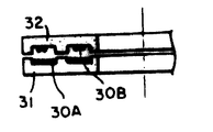
제3도는 신호 전달로가 되는 로터리 트랜스의 단면도.3 is a sectional view of a rotary transformer serving as a signal transmission path.
제4도는 회전헤드형 테이프 레코더에 의한 테이프 주행상태와 헤드의 배치를 나타낸 설명도.4 is an explanatory diagram showing the tape traveling state and the arrangement of the head by the rotary head type tape recorder.
제5도는 종래의 실린더 유닛의 신호 전달장치의 결선을 나타낸 회로도.5 is a circuit diagram showing the connection of the signal transmission device of the conventional cylinder unit.
제6도는 종래의 실린더 유닛의 반단면 측면도이다.6 is a half sectional side view of a conventional cylinder unit.
* 도면의 주요부분에 대한 부호의 설명* Explanation of symbols for main parts of the drawings
1 : 고정실린더 2 : 회전실린더1: fixed cylinder 2: rotating cylinder
3C, 3D : 모니터용 자기헤드 3A, 3B : 기록용 자기헤드3C, 3D: Magnetic head for
4 : 회전축 13 : 기록 증폭기4: axis of rotation 13: recording amplifier
14 : 재생 증폭기 30A, 30B : 신호전달로14:
31 : 스테이터트랜스 32 : 로터트랜스31: Stator transformer 32: Rotor transformer
본 발명은 화상이나 음성을 기록 재생하는 회전 헤드형 테이프 레코더의 실린더 유닛에 관한 것이며, 특히 실린더를 소형화 했을 경우에 복수의 자기헤드로부터의 신호를 확실하게 전달할 수 있도록 한 신호전달 장치에 관한 것이다.BACKGROUND OF THE INVENTION 1. Field of the Invention [0001] The present invention relates to a cylinder unit of a rotary head type tape recorder for recording and reproducing images and audio, and more particularly to a signal transmission device capable of reliably transferring signals from a plurality of magnetic heads when a cylinder is downsized.
제5도는 종래의 실린더 유닛에 있어서의 자기헤드의 결선을 나타낸 회로도, 제6도는 종래의 실린더 유닛의 반단면 측면도이다.5 is a circuit diagram showing the connection of the magnetic head in the conventional cylinder unit, and FIG. 6 is a half sectional side view of the conventional cylinder unit.
부호 1은 고정실린더이고, 2는 회전실린더이다.Reference numeral 1 is a fixed cylinder, and 2 is a rotation cylinder.
회전실런더(2)에는 4개의 자기헤드(3A~3D)가 고정설치되어 있다. 회전실린더(2)는 회전축(4)에 고정되어 있다. 회전축(4)은 고정실린더(1)에 대하여 베어링(5)을 통해서 회전자유롭게 지지되어 있다. 회전축(4)의 하단에는 지지판(6)이 설치되고 그 위에 로터자석(7)이 설치되고, 이 로터자석(7)이 고정실린더(1)의 하단의 스테이터코일(8)에 대향되어 있다. 스테이터코일(8)에 전류가 흐르게 되면 로터자석(7)이 회전구동되고 이와 동시에 회전실린더(2)가 회전하도록 되어 있다.Four
고정실린더(1)에는 스테이터트랜스(11)가, 회전실린더(2)에는 로터트랜스(12)가 고정되어 있다. 양트랜스(11), (12)에는 4개씩의 홈이 형성되어 있고 홈부분이 서로 대향하고 있으며 또한 그 내부에 코일이 감겨져 있다. 로터트랜스(12)축의 코일은 회전실린더(2)에 탑재된 각 자기헤드(3A~3D)에 접속되어 있고, 스테이터트랜스(11)측의 코일은 제5도에 나타낸 바와 같이 기록 증폭기(13)와 재생 증폭기(14)에 접속되어 있다. 즉 스테이터트랜스(11)와 로터트랜스(12)와의 사이에는 4개의 신호 전달로(10A), (10B), (10C), (10D)가 형성된다.The stator transformer 11 is fixed to the fixed cylinder 1, and the
이 신호 전달로(10A), (10B)에 의하여 자기헤드(3A), (3B)가 기록 증폭기(13)에 접속되고, 10C와 10D에 의하여 자가헤드(3C), (3D)가 재생 증폭기(14)에 연결된다.The
최근 이 종류의 실린더 유닛을 사용한 회전헤드형 테이프 레코더에서는 자기의소형화가 추진되고 있으며, 따라서 실린더 유닛 자체의 직경도 작은것이 요구된다.In recent years, miniaturization of magnetism has been promoted in the rotary head type tape recorder using this type of cylinder unit, and therefore, the diameter of the cylinder unit itself is also required.
소형화를 위하여 고정실린더(1) 및 회전실린더(2)의 외경을 작게하면 스테이터 트랜스(11) 및 로터트랜스(12)도 당연히 소형화 되어야 한다. 이와 반대로 최근의 회전헤드형 테이프 레코더에 있어서는 특수 재생 및 기타 기능의 다양화에 대처할 수 있게하기 위하여 탑재되는 헤드수가 많아지고 있다.For miniaturization, if the outer diameters of the fixed cylinder 1 and the rotating
그 결과 스테이터 트랜스(11)와 로터트랜스(12)에 의한 신호 전달로(10A~10D)의 간격이 좁혀지고, 또 이 신호 전달로(10A~10D)에 있어서의 트랜스 코일의 권선수도 적게하는 경향이다. 이로 인하여 각 전달로에 있어서의 신호 전달의 확실성이 저하하고, 혹은 신호 전달로(10A~10D)가 서로 접근되어 있기 때문에 기록 증폭기(13)로의 신호와 재생 증폭기(14)로의 신호와의 사이에 크로스토오크가 발생할 가능성도 있다.As a result, the distance between the signal transmission paths 10A to 10D by the stator transformer 11 and the
이에 대처하기 위하여 종래에는 제5도에 나타낸 바와 같이 기록 증폭기(13)의 신호 전달계에 스위치회로(15)를 설치하고, 또 재생 증폭기(14)로의 신호 전달계에 스위치회로(16)를 설치하였다. 그러므로 예를 들어 자기헤드(3A), (3C)가 테이프에 접촉하고 있을 때에는 자기헤드(3B), (3D)의 신호 전달로를 차단하도록 작동하게 된다.In order to cope with this, conventionally, as shown in FIG. 5, the
그러나 제5도에 나타낸 바와 같은 스위치회로(15), (16)을 설치하면 그만큼 회로구성이 복잡해진다는 결점이 있다. 또한 스테이터트랜스(11)와 로터트랜스(12)의 홈 가공에도 정밀이 요하게 되고 가공이 점점 어려워져서 부품의 가공비가 높아진다는 결점도 생기게 된다.However, there is a drawback that if the
본 발명은 상기 종래의 문제점을 감안하여 이루어진 것이며 스테이터트랜스와 로터트랜스 등에 의한 신호전달 수단의 구조를 간략화하여 소형화를 가능하게 하고, 또한 신호간의 크로스토오크가 발생하는 문제도 없어지고 또 스위치회로 등의 존재도 불필요하게 되는 실린더 유닛의 신호장치를 제공하는 것을 목적으로 한다.SUMMARY OF THE INVENTION The present invention has been made in view of the above-mentioned conventional problems, and the structure of the signal transmission means by the stator transformer and the rotor transformer can be simplified to reduce the size of the signal transmission means. It is an object of the present invention to provide a signal device of a cylinder unit, which also becomes unnecessary.
본 발명에 의한 신호 전달장치는 고정실린더와 회전실린더를 가지며 회전실린더에는 복수의 자기헤드가 설치됨과 동시에 고정실린더와 회전실린더의 사이에 접촉식 또는 비접촉식의 신호 전달로가 설치된 실린더 유닛에 있어서, 자기헤드의 수보다도 신호 전달로의 수가 작고, 한개의 신호 전달로에 복수의 자기헤드가 접속되는 것을 특징으로한다.The signal transmission device according to the present invention has a fixed cylinder and a rotating cylinder, a plurality of magnetic heads are installed in the rotating cylinder and at the same time a cylinder unit provided with a contact or contactless signal transmission path between the fixed cylinder and the rotating cylinder, The number of signal transmission paths is smaller than the number of heads, and a plurality of magnetic heads are connected to one signal transmission path.
본 발명은 공통의 회로에 연결되는 한개의 신호 전달로에 복수의 자기헤드를 접속하고 이 복수의 자기헤드의 한개가 테이프에 접촉하고 있을 때는 다른 자기헤드가 테이프에 접촉하지 않도록 배치하고, 한개의 신호 전달로에 의하여 어느쪽이든지 하나의 자기헤드의 신호를 번갈아 전달할 수 있도록 함으로써 신호 전달로의 수의 삭감과 신호 전달 기구의 간략화를 도모할 수 있게 한 것이다.The present invention connects a plurality of magnetic heads to one signal transmission path connected to a common circuit, and when one of the plurality of magnetic heads contacts the tape, the other magnetic head does not contact the tape. It is possible to reduce the number of signal transmission paths and simplify the signal transmission mechanism by allowing the signal transmission paths to alternately transmit signals from one magnetic head to either side.
이하 본 발명의 실시예를 제1도~제4도에 따라 설명한다.Hereinafter, embodiments of the present invention will be described with reference to FIGS. 1 to 4.
제1도는 실린더 유닛에 있어서의 자기헤드의 결선을 나타낸 회로도, 제2도는 실린더 유닛의 반단면 측면도, 제3도는 비접촉식의 신호 전달로를 확대시켜 나타낸 단면도, 제4도는 회전 실린더식 테이프 레코더의 헤드배치와 테이프 주행상태를 나타낸 설명도이다.1 is a circuit diagram showing the connection of a magnetic head in a cylinder unit, FIG. 2 is a half sectional side view of the cylinder unit, FIG. 3 is a sectional view showing an enlarged contactless signal transmission path, and FIG. 4 is a head of a rotating cylindrical tape recorder. It is explanatory drawing which showed arrangement | positioning and a tape running state.
제4도에 있어서 부호 20은 테이프카세트이다. 테이프카세트(20)내에는 공급 리일(21)과 권취리일(22)이 설치되어 있고, 양 리일(21), (22)의 사이에 테이프(T)가 감겨져 있다. 또한 부호(23a~23h)는 테이프(T)를 지지하고 주행시키는 로울러이다. 이 로울러(23a~23h) 중 23a와 23c는 테이프카세트(20)안에서 테이프(T)를 인출하기 위한 인출 로울러이다. 그리고 24a와 24b는 테이프(T)를 실린더 유닛에 붙도록 누르는 부재이다.In FIG. 4, the code |
제2도에 나타낸 바와 같이 실린더 유닛을 고정실린더(1)와 회전실린더(2)로 구성된다. 제6도에 나타내 것과 같이 회전실린더(2)는 4개의 자기헤드(3A~3D)가 고정된다. 회전실린더(2)는 회전축(4)에 고정된다. 회전축(4)은 고정실린더(1)에 대하여 베어링(5)을 거쳐서 회전자유롭게 지지된다. 회전축(4)의 하단에는 지지판(6)이 설치되고 그 위에 로터자석(7)이 설치되고 이 로터자석(7)이 고정실린더(1)의 하단의 스테이터코일(8)에 대향된다. 이 스테이터코일(8)에 흐르는 전류에 의해 로터자석(7)이 회전구동되고, 이와 동시에 회전실린더(2)가 회전되도록 한다.As shown in FIG. 2, the cylinder unit is comprised by the fixed cylinder 1 and the rotating
제4도에 나타낸 바와 같이 4개의 자기헤드(3A~3D)는 회전실린더(2) 상에서 중심으로부터의 배치 각도(θ)가 약 90도로 분배된다. 4개의 자기헤드(3A~3D)중 3A와 3B는 기록용의 샌더스트(Sendust)헤드이고, 3C와 3D는 후속하는 모니터용으로 작동하는 페라이트헤드이다.As shown in FIG. 4, the four
상기와 같이 각 헤드(3A~3D)는 약 90도의 배치각도이기 때문에 같은 기록용헤드(3A), (3B)는 어느 한쪽이 테이프(T)에 접촉하고 있을 때에 다른 한쪽은 비접촉상태로 된다. 모니터용헤드(3C), (3D)도 마찬가지이다.As described above, each of the
상기 고정실린더(1)에는 스테이터트랜스(31)가, 회전실린더(2)에는 로터트랜스(32)가 설치된다. 스테이트랜스(31)와 로터트랜스(32)에는 서로 대향하는 2조의 홈이 형성된다. 이 홈에 의하여 2조의 신호전송로(3A), (30B)가 형성된다.The stationary cylinder 1 is provided with a
제1도의 회로에 나타낸 바와 같이, 기록용헤드(3A), (3B)는 동일 신호로에 접속되고 신호 전달로(30A)를 거쳐 기록 증폭기(13)에 접속된다. 그리고 모니터용헤드(3C), (3D)는 동일 신호로에 접속되고 신호 전달로(30B)를 거쳐 재생 증폭기(14)에 접속된다. 이와 같이 4개의 헤드에 대하여 신호 전달로가 30A와 30B 의 2조뿐이므로 스테이터트랜스(31)와 로터트랜스(32)를 소형화 했다 하더라도 홈의 폭을 넓게 할 수가 있다. 따라서 홈 내부의 코일의 감김수도 많게 할 수가 있다.As shown in the circuit of FIG. 1, the recording heads 3A and 3B are connected to the same signal path and are connected to the
다음에 동작에 관하여 설명한다.Next, the operation will be described.
테이프카세트(20)를 장전하면 인출로울러(23b), (23c)가 테이프(T)를 인출하여 테이프(T)를 실린더 유닛에 감아 붙인다. 테이프(T)는 공급리일(21)로부터 권취리일(22)로 이송된다. 동시에 스테이터코일(8)에 전류가 흐르고 회전축(4)과 함께 회전실린더(2)가 회전구동된다. 그리고 기록용헤드(3A), (3B)에 의하여 기록동작이 행해지고 모니터용헤드(3C), (3D)에 의하여 재생동작이 행해진다.When the
기록용헤드(3A), (3B)는 동일신호 전달로(30A)에 접속되나 한쪽의 헤드(3A)가 테이프(T)에 접촉되었을 때에는 다른쪽의 헤드(3B)는 테이프(T)로부터 떨어져 있다.The recording heads 3A and 3B are connected to the same
그러므로 동일 신호 전달로(30A)에서는 헤드(3A), (3B)에 의한 기록신호가 번갈아 전달되어 기록 증폭기(13)에 입력된다. 마찬가지로 모니터용헤드(3C), (3D)도 그 신호가 신호 전달로(30B)에 번갈아 전달되어 재생 증폭기(14)에 입력된다.Therefore, in the same
그리고 본 실시예에서는 신호 전달로를 트랜스를 사용한 비접촉식 기구로서 설명하였으나, 슬립링 등과 같은 접촉식의 신호 전달로를 사용해도 된다.In the present embodiment, the signal transmission path has been described as a non-contact mechanism using a transformer, but a contact signal transmission path such as a slip ring may be used.
이상과 같이 본 발명에 의하면 다음과 같은 효과를 갖는다.As mentioned above, according to this invention, it has the following effects.
복수의 헤드를 회전실린더에 설치했을 경우에도 고정실린더로의 신호 전달로가 헤드의 수보다 적어도 되므로 신호 전달장치의 구조가 간단해진다.Even when a plurality of heads are provided in the rotating cylinder, the signal transmission path to the fixed cylinder is smaller than the number of heads, thereby simplifying the structure of the signal transmission device.
신호 전달로로서 로터트랜스를 사용하는 경우에는 신호 전달로를 형성하는 홈의 수를 적게할 수 있으므로 트랜스 자체를 소경(小徑)으로 할 수 있어 플래어전체의 소형화에 기여할 수 있게 된다. 또 홈폭을 넓게하 수 있으므로 트랜스 코일의 권선도 많게 할 수 있어 신호의 전달효율을 향상시킬 수가 있게 된다.When the rotor transformer is used as the signal transmission path, the number of grooves forming the signal transmission path can be reduced, so that the transformer itself can be made small in diameter, contributing to the miniaturization of the entire flare. In addition, since the groove width can be widened, the winding of the transformer coil can be increased, thereby improving signal transmission efficiency.
신호 전달로의 수가 적으므로 신호간의 크로스토오크도 생기기 어렵게 된다.Since the number of signal transmission paths is small, crosstalk between signals is less likely to occur.
Claims (2)
Applications Claiming Priority (3)
| Application Number | Priority Date | Filing Date | Title |
|---|---|---|---|
| JP85-69427 | 1985-04-02 | ||
| JP60069427A JPS61229203A (en) | 1985-04-02 | 1985-04-02 | Signal transmitter for cylinder unit |
| JP69,427 | 1985-04-02 |
Publications (2)
| Publication Number | Publication Date |
|---|---|
| KR860008530A KR860008530A (en) | 1986-11-15 |
| KR900000626B1 true KR900000626B1 (en) | 1990-02-01 |
Family
ID=13402309
Family Applications (1)
| Application Number | Title | Priority Date | Filing Date |
|---|---|---|---|
| KR1019850008665A KR900000626B1 (en) | 1985-04-02 | 1985-11-20 | Signal transfer device of cylinder unit |
Country Status (4)
| Country | Link |
|---|---|
| JP (1) | JPS61229203A (en) |
| KR (1) | KR900000626B1 (en) |
| DE (1) | DE3603239A1 (en) |
| GB (1) | GB2173341B (en) |
Families Citing this family (12)
| Publication number | Priority date | Publication date | Assignee | Title |
|---|---|---|---|---|
| DE3705928A1 (en) * | 1987-02-25 | 1988-09-08 | Broadcast Television Syst | MAGNETIC TAPE DEVICE WITH DEVICE FOR THE CONTACTLESS TRANSFER OF SIGNALS BETWEEN RELATIVELY MOVING COMPONENTS |
| DE3713429A1 (en) * | 1987-04-22 | 1988-11-03 | Thomson Brandt Gmbh | RECORDER WITH A ROTATING HEAD DRUM |
| JPH01116902A (en) * | 1987-10-30 | 1989-05-09 | Hitachi Ltd | Magnetic recording and reproducing device |
| JPH0268708A (en) * | 1988-09-01 | 1990-03-08 | Sharp Corp | Rotary head type magnetic tape device |
| JP2571111B2 (en) * | 1988-12-05 | 1997-01-16 | アルプス電気株式会社 | Rotating head type magnetic recording / reproducing device |
| KR910009850B1 (en) * | 1989-02-28 | 1991-11-30 | 삼성전자 주식회사 | Input signal checking method and device of d.a.t. |
| JPH02123713U (en) * | 1989-03-20 | 1990-10-11 | ||
| US5532887A (en) * | 1989-05-23 | 1996-07-02 | Kabushiki Kaisha Toshiba | Magnetic recording and reproduction apparatus |
| US5276565A (en) * | 1989-05-23 | 1994-01-04 | Kabushiki Kaisha Toshiba | Rotary type magnetic recording and reproduction apparatus |
| US5434720A (en) * | 1989-05-23 | 1995-07-18 | Kabushiki Kaisha Toshiba | Magnetic recording and reproduction apparatus with plural heads |
| JPH03125301A (en) * | 1989-10-11 | 1991-05-28 | Sankyo Seiki Mfg Co Ltd | Digital signal recording and reproducing device |
| JP3649587B2 (en) | 1998-05-25 | 2005-05-18 | アルプス電気株式会社 | Rotating head device |
Family Cites Families (12)
| Publication number | Priority date | Publication date | Assignee | Title |
|---|---|---|---|---|
| GB747467A (en) * | 1953-08-14 | 1956-04-04 | Gen Electric | Improvements in and relating to programming control systems |
| GB887768A (en) * | 1959-03-18 | 1962-01-24 | Nat Res Dev | Improvements in and relating to the transmission and/or recording of speech |
| BE668533A (en) * | 1964-08-19 | |||
| FR1493611A (en) * | 1966-06-28 | 1967-09-01 | Bull General Electric | computer connectable magnetic tape input / output element |
| US3555203A (en) * | 1966-11-30 | 1971-01-12 | Us Army | Method of and apparatus for time adjustment of information |
| US3536856A (en) * | 1967-09-20 | 1970-10-27 | Ampex | Record-reproduce mode selection without mechanical relays |
| US4099210A (en) * | 1976-10-04 | 1978-07-04 | Dolby Dale P | Rotating transducing head assembly |
| SU888184A1 (en) * | 1977-12-28 | 1981-12-07 | Предприятие П/Я Р-6707 | Device for reproducing from magnetic tape |
| JPS6112572Y2 (en) * | 1979-03-14 | 1986-04-19 | ||
| JPS6134753A (en) * | 1984-07-25 | 1986-02-19 | Hitachi Ltd | Magnetic recording and reproducing device of rotary head type |
| GB2167889B (en) * | 1984-11-28 | 1988-05-11 | Sony Corp | Video tape recorders |
| JPS61187103A (en) * | 1985-02-14 | 1986-08-20 | Sony Corp | Device for recording and reproducing audio signal |
-
1985
- 1985-04-02 JP JP60069427A patent/JPS61229203A/en active Pending
- 1985-11-20 KR KR1019850008665A patent/KR900000626B1/en not_active IP Right Cessation
-
1986
- 1986-01-08 GB GB8600341A patent/GB2173341B/en not_active Expired
- 1986-02-03 DE DE19863603239 patent/DE3603239A1/en active Granted
Also Published As
| Publication number | Publication date |
|---|---|
| KR860008530A (en) | 1986-11-15 |
| GB8600341D0 (en) | 1986-02-12 |
| GB2173341A (en) | 1986-10-08 |
| JPS61229203A (en) | 1986-10-13 |
| DE3603239C2 (en) | 1989-11-09 |
| GB2173341B (en) | 1989-06-28 |
| DE3603239A1 (en) | 1986-10-09 |
Similar Documents
| Publication | Publication Date | Title |
|---|---|---|
| KR900000626B1 (en) | Signal transfer device of cylinder unit | |
| US4058844A (en) | Low-mass short-stroke voice-coil actuator for integrated disk file module | |
| KR960005117B1 (en) | Rotary magnetic head device | |
| JP3649587B2 (en) | Rotating head device | |
| US6297631B1 (en) | Magnetic signal reproducing method and apparatus using magneto-resistive effect element with increased sense current | |
| US4924329A (en) | Rotary drum apparatus for a magnetic recording and reproducing device | |
| KR100309434B1 (en) | Magnetic writing/reading device | |
| KR100562694B1 (en) | Rotating Magnetic Head Device | |
| JPS63259819A (en) | Rotary head for magnetic recording and reproducing device | |
| KR19980081735A (en) | Rotary magnetic head device | |
| JPH10233013A (en) | Non-contact type transmission device and rotary magnetic head device equipped with the same | |
| JP2569959B2 (en) | Rotating head device | |
| KR940003448Y1 (en) | Video signal transfer device for vcr cylinder | |
| JP3812440B2 (en) | Magnetic recording / reproducing device | |
| JP4032586B2 (en) | Rotating drum and magnetic tape recording / reproducing apparatus using the same | |
| JPH0682449B2 (en) | Rotating drum device | |
| KR100194046B1 (en) | Rotary Transformer Assembly for Rotary Rotary Head Drum Unit | |
| JP2783717B2 (en) | Rotary head drum device for magnetic recording / reproducing device | |
| KR100189935B1 (en) | Head drum | |
| JPH02227801A (en) | Rotary drum for rotary magnetic head | |
| JP2915054B2 (en) | Rotating head cylinder device | |
| JP2005346856A (en) | Head drum apparatus and magnetic recording and reproducing apparatus | |
| JPH10172102A (en) | Rotary magnetic head device | |
| JPH01107366A (en) | Magnetic disk device | |
| JP2001134915A (en) | Rotary drum, and magnetic tape recording/reproducing device using same |
Legal Events
| Date | Code | Title | Description |
|---|---|---|---|
| A201 | Request for examination | ||
| E902 | Notification of reason for refusal | ||
| G160 | Decision to publish patent application | ||
| E701 | Decision to grant or registration of patent right | ||
| GRNT | Written decision to grant | ||
| FPAY | Annual fee payment |
Payment date: 19930118 Year of fee payment: 4 |
|
| LAPS | Lapse due to unpaid annual fee |