KR900000091B1 - Display devices of color picture image - Google Patents
Display devices of color picture image Download PDFInfo
- Publication number
- KR900000091B1 KR900000091B1 KR1019850006979A KR850006979A KR900000091B1 KR 900000091 B1 KR900000091 B1 KR 900000091B1 KR 1019850006979 A KR1019850006979 A KR 1019850006979A KR 850006979 A KR850006979 A KR 850006979A KR 900000091 B1 KR900000091 B1 KR 900000091B1
- Authority
- KR
- South Korea
- Prior art keywords
- display
- memory
- color
- screen
- signal
- Prior art date
Links
Images


Classifications
-
- G—PHYSICS
- G06—COMPUTING; CALCULATING OR COUNTING
- G06F—ELECTRIC DIGITAL DATA PROCESSING
- G06F3/00—Input arrangements for transferring data to be processed into a form capable of being handled by the computer; Output arrangements for transferring data from processing unit to output unit, e.g. interface arrangements
- G06F3/14—Digital output to display device ; Cooperation and interconnection of the display device with other functional units
-
- G—PHYSICS
- G09—EDUCATION; CRYPTOGRAPHY; DISPLAY; ADVERTISING; SEALS
- G09G—ARRANGEMENTS OR CIRCUITS FOR CONTROL OF INDICATING DEVICES USING STATIC MEANS TO PRESENT VARIABLE INFORMATION
- G09G1/00—Control arrangements or circuits, of interest only in connection with cathode-ray tube indicators; General aspects or details, e.g. selection emphasis on particular characters, dashed line or dotted line generation; Preprocessing of data
- G09G1/06—Control arrangements or circuits, of interest only in connection with cathode-ray tube indicators; General aspects or details, e.g. selection emphasis on particular characters, dashed line or dotted line generation; Preprocessing of data using single beam tubes, e.g. three-dimensional or perspective representation, rotation or translation of display pattern, hidden lines, shadows
- G09G1/14—Control arrangements or circuits, of interest only in connection with cathode-ray tube indicators; General aspects or details, e.g. selection emphasis on particular characters, dashed line or dotted line generation; Preprocessing of data using single beam tubes, e.g. three-dimensional or perspective representation, rotation or translation of display pattern, hidden lines, shadows the beam tracing a pattern independent of the information to be displayed, this latter determining the parts of the pattern rendered respectively visible and invisible
- G09G1/16—Control arrangements or circuits, of interest only in connection with cathode-ray tube indicators; General aspects or details, e.g. selection emphasis on particular characters, dashed line or dotted line generation; Preprocessing of data using single beam tubes, e.g. three-dimensional or perspective representation, rotation or translation of display pattern, hidden lines, shadows the beam tracing a pattern independent of the information to be displayed, this latter determining the parts of the pattern rendered respectively visible and invisible the pattern of rectangular co-ordinates extending over the whole area of the screen, i.e. television type raster
- G09G1/165—Details of a display terminal using a CRT, the details relating to the control arrangement of the display terminal and to the interfaces thereto
-
- G—PHYSICS
- G06—COMPUTING; CALCULATING OR COUNTING
- G06F—ELECTRIC DIGITAL DATA PROCESSING
- G06F3/00—Input arrangements for transferring data to be processed into a form capable of being handled by the computer; Output arrangements for transferring data from processing unit to output unit, e.g. interface arrangements
- G06F3/14—Digital output to display device ; Cooperation and interconnection of the display device with other functional units
- G06F3/153—Digital output to display device ; Cooperation and interconnection of the display device with other functional units using cathode-ray tubes
-
- G—PHYSICS
- G09—EDUCATION; CRYPTOGRAPHY; DISPLAY; ADVERTISING; SEALS
- G09G—ARRANGEMENTS OR CIRCUITS FOR CONTROL OF INDICATING DEVICES USING STATIC MEANS TO PRESENT VARIABLE INFORMATION
- G09G5/00—Control arrangements or circuits for visual indicators common to cathode-ray tube indicators and other visual indicators
- G09G5/02—Control arrangements or circuits for visual indicators common to cathode-ray tube indicators and other visual indicators characterised by the way in which colour is displayed
-
- G—PHYSICS
- G09—EDUCATION; CRYPTOGRAPHY; DISPLAY; ADVERTISING; SEALS
- G09G—ARRANGEMENTS OR CIRCUITS FOR CONTROL OF INDICATING DEVICES USING STATIC MEANS TO PRESENT VARIABLE INFORMATION
- G09G2360/00—Aspects of the architecture of display systems
- G09G2360/18—Use of a frame buffer in a display terminal, inclusive of the display panel
Abstract
Description
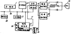
제1도는 본원 발명의 일실시예에 의한 표시장치의 전체구성을 나타낸 블록도.1 is a block diagram showing an overall configuration of a display device according to an embodiment of the present invention.
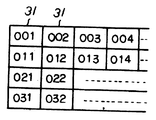
제2도는 모노크롬 표시의 경우의 도트데이터와 화면과의 관련을 나타낸 설명도.2 is an explanatory diagram showing the relationship between dot data and a screen in the case of monochrome display.
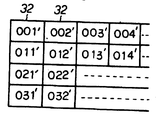
제3도는 컬러표시의 경우의 도트데이터와 화면표시와의 관련을 나타낸 설명도.3 is an explanatory diagram showing the relationship between dot data and screen display in the case of color display.
제4도는 컬러표시회로 및 모노크롬 표시회로의 상세를 나타낸 블록도.4 is a block diagram showing details of a color display circuit and a monochrome display circuit.
제5도는 컬러표시회로 및 모노크롬 표시회로의 관련하는 신호를 나타낸 타임차아트.5 is a time difference art showing related signals of a color display circuit and a monochrome display circuit.
본원 발명은 라스터스캔(rasterscan)에 의해 화면에 화상을 표시하는 형식의 컬러화상의 표시장치에 관한 것이다.The present invention relates to a display device of a color image in the form of displaying an image on a screen by raster scan.
CRT 디스플레이 장치등에 있어서 단색화상(單色畵像)과 똑같은 방법으로 컬러화상을 표시하려고 하면, 각기 컬러에 대응하여 표시용의 메모리가 필요해져 단색화상표시의 경우에 비해 메모리 용량이 증가한다고 하는 문제가 있다.In the case of displaying color images in the same way as monochrome images in a CRT display device, a memory for display is required corresponding to each color, and the memory capacity increases compared with the case of monochrome image display. There is.
이와 같은 메모리 용량의 증량을 피하기 위한 선행기술로서는 일본국 특개소 55-23519호 공보에 개시되어 있는 방식이 알려져 있다. 이 방식에 있어서는 1화면의 도트수(단색화상의 화소수)와 같은 비트수의 메모리가 4개의 구분으로 분할되며, 그중의 3개의 메모리 구분의 각각의 영역에 R(적색), G(녹색), 및 B(청색)의 컬러화상정보 성분이 기입되어 있다. 그리고 상기 구분된 각 메모리 구분마다의 선두 어드레스에서 상대적으로 동일 어드레스의 R, G, B 정보가 동시에 독출되며, 독출된 1조의 R, G, B 정보는 대응하는 CRT의 화면상의 1컬러화소를 구성하는 4도트로 표시된다. 이래서 해상도(解象度)는 저하하지만 단색화상의 1화면분의 메모리 용량으로 컬러화상을 표시할 수 있다.As a prior art for avoiding such an increase in memory capacity, a method disclosed in Japanese Patent Laid-Open No. 55-23519 is known. In this method, a memory having the same number of bits as the number of dots (monochrome pixels) of one screen is divided into four divisions, and R (red) and G (green) are divided into three regions of each of the three memory divisions. , And B (blue) color image information components are written. R, G, and B information of the same address are simultaneously read out from the head address of each of the divided memory sections, and the set of R, G, and B information that is read constitutes one color pixel on the screen of the corresponding CRT. Is represented by 4 dots. As a result, the resolution is lowered, but the color image can be displayed with a memory capacity of one screen of a monochrome image.
그러나, 이와 같은 방식에서는 하나의 메모리를 복수의 구분의 메모리로 분할하므로, 고집적도의 메모리를 사용할 수 없고, 또 각 메모리 구분마다의 선두 어드레스에서 상대적으로 동일 어드레스를 동시에 독출하므로, 메모리 독출에 관련하는 논리가 복잡화한다고 하는 문제가 있다.However, in this method, since one memory is divided into a plurality of divisions of memory, a memory of high density cannot be used, and the same address is simultaneously read out from the head address of each division of memory so that it is related to memory reading. There is a problem that the logic is complicated.
본원 발명의 목적은 메모리 분할을 하지 않고 단색표시의 경우와 동등한 메모리 용량으로 컬러화상을 표시하는 컬러화상의 표시방법 및 장치를 제공하는데 있다.SUMMARY OF THE INVENTION An object of the present invention is to provide a color image display method and apparatus for displaying a color image with a memory capacity equivalent to that of monochrome display without performing memory division.
또, 본원 발명의 다른 목적으로서, 메모리 분할을 하지 않고, 컬러표시의 경우나 단색표시의 경우도 메모리의 독출제어를 똑같이 하여, 메모리의 주변 논리를 단순화시킨 컬러화상의 표시방법 및 장치를 제공하는데 있다.In addition, as another object of the present invention, there is provided a color image display method and apparatus which simplifies the peripheral logic of the memory by performing the same memory read control in the case of color display or monochrome display without performing memory division. It is.
또, 본원 발명의 다른 목적으로서 화면의 화소수가 많은 표시장치로 고집적도의 메모리를 사용할 수 있는 컬러화상의 표시방법 및 장치를 제공하는데 있다.Another object of the present invention is to provide a display method and apparatus for displaying a color image that can use a high density memory as a display device having a large number of pixels on the screen.
또한 본원 발명의 다른 목적은 간단한 구성으로 화면의 반짝거림을 방지할 수 있는 컬러화상의 표시방법 및 장치를 제공하는데 있다. 그리고 본원 발명은 화면에 표시해야 할 그래픽 디스플레이의 코오드가 화면상의 표시위치에 대응해서 격납되며, 화면의 라스터스캔과 동기해서 독출되는 제1의 메모리와, 화면상의 1컬러화소당 N 비트의 컬러표시용 도트패턴 데이터가 격납되는 제2의 메모리와, 상기 제1의 메모리의 출력데이터에서 컬러표시용의 R, G, B 신호를 작성하고, 화면표시수단에 송출하는 회로를 구비하며, 제1의 메모리 및 제2의 메모리의 독출제어를 단색표시의 경우와 컬러표시의 경우를 똑같이 제어하고, 독출한 데이터를 캐랙터애트리뷰우트에 의거하여 단색표시용인지 컬러표시용인지를 판별하며, 컬러표시용일 때에 컬러표시용 도트패턴 데이터의 N 비트로 화면상의 N 도트로 이루어진 컬러화소의 표시색을 지정시켜 컬러화상을 표시시키는 것이다.In addition, another object of the present invention is to provide a display method and apparatus for displaying a color image that can prevent the screen from shining with a simple configuration. In addition, according to the present invention, a code of a graphic display to be displayed on a screen is stored in correspondence with a display position on the screen, the first memory read out in synchronization with the raster scan of the screen, and N bits of color per color pixel on the screen. And a second memory for storing display dot pattern data, and a circuit for generating R, G, and B signals for color display from the output data of the first memory and sending them to the screen display means. Read-out control of the memory and the second memory is controlled in the same way as for the monochrome display and for the color display, and the read data is judged for the monochrome display or the color display based on the character attribute context. Is used to display a color image by specifying a display color of a color pixel composed of N dots on the screen by N bits of the dot pattern data for color display.
또 짝수라스터와 홀수라스터에서 컬러화소의 표시색을 다르게끔 색표시를 제어시켜 화면의 반짝거림을 방지한다. 다음에, 본원 발명의 일실시예에 대해 도면에 의거하여 상세히 설명한다.In addition, even-numbered and odd-numbered rasters control the display of colors so that the display colors of the color pixels are different to prevent the screen from glittering. Next, an embodiment of the present invention will be described in detail with reference to the drawings.
제1도는 본원 발명의 일실시예에 의한 표시장치의 블록도이다. 제1도에 있어서, (1)은 표시장치의 전체의 제어를 관장하는 주제어부이며, 마이크로프로세서 등에 의해 구성되어 있다. (2)는 주제어부(1)의 프로그램을 투입(load)하는 IO 어댑터이며, (3)은 동 프로그램등을 격납하기 위한 주메모리이다.1 is a block diagram of a display device according to an embodiment of the present invention. In FIG. 1,
(6)은 단색표시용 또는 컬러표시용의 도트패턴 데어터가 격납되는 도트패턴 메모리이다. (5)는 표시캐랙터의 코오드를 격납하는 화면 메모리이며, 그 출력신호(11)는 도트패턴 메모리(6)에 어드레스신호의 일부로서 주어진다. (4)는 표시캐랙터의 속성 데이터인 캐랙터애트리뷰우트를 격납하는 캐랙터애트리뷰우트메모리이며, 이 캐랙터애트리뷰우트메모리(4)에 격납되는 캐랙터애트리뷰우트의 특정비트는 단색표시와 컬러표시의 절환제어에 사용된다. 또 캐랙터애트리뷰우트메모리(4)는 화면메모리(5)와 대응하고 있으며, 예를 들어 화면메모리(5)의 캐랙터코오드 2바이트씩에 대해, 캐랙터애트리뷰우트메모리(4)의 1바이트씩이 순차 대응한다. (14)는 화면메모리(5)를 독출하기 위한 어드레스신호를 발생하는 어드레스회로이다. 주제어부(1), IO 어댑터(2), 주메모리(3), 도트패턴메모리(6), 화면메모리(5) 및 캐랙터애트리뷰우트메모리(4)는 키이보오드(18)와 함께 버스(10)에 의해 접속되어 있다. 도트패턴메모리(6), 화면메모리(5) 및 캐랙터애트리뷰우트메모리(4)의 데이터기입은 예를 들어 키이보오드(18)에서 입력된 데이터에 대해 버스(10)를 통해 주제어부(1)의 제어에 의해 행해진다. (7)은 컬러표시회로이며, 도트패턴메모리(6)에서 입력된 도트신호에 따라 CRT(19)에 컬러표시를 위한 적색정보(R), 녹색정보(G), 청색정보(B) 신호를 송출하는 것이다. 또, (8)은 단색표시회로이며, 입력된 도트신호에 따라 CRT(19)에 단색표시를 위한 도트신호를 송출하는 것이다. 컬러표시회로(7), 및 단색표시회로(8)의 상세에 대해서는 후술한다.(6) is a dot pattern memory in which dot pattern data for monochrome display or color display is stored. Denoted at 5 is a screen memory for storing the code of the display character, and its output signal 11 is given to the
G 신호는 단색표시 또는 컬러표시의 도트신호로서 사용하기 위해 OR 게이트(9)에 의해 하나의 신호로 정리되어 송출된다. 도트신호(Y)는 단색표시시에 사용한다. (15)은 플립플롭이며, 화면메모리(5)의 독출에 동기해서 캐랙터애트리뷰우트메모리(4)에서 독출되는 캐랙터애트리뷰우트의 톡정비트의 신호에 의해 상태가 제어된다. 이 플립플롭(15)의 출력신호(13)는 컬러/단색절환신호로서 컬러표시회로(7)와 단색표시회로(8)에 주어진다.The G signal is collectively sent out as one signal by the OR gate 9 for use as a dot signal of monochrome display or color display. The dot signal Y is used for monochrome display.
그리고, 이 캐랙터애트리뷰우트의 특정비트 이외의 비트의 신호는 휘도(輝度) 제어나 풀링(Pulling)제어 등을 위해 컬러표시회로(7)와 단색표시회로(8)에 주어지지만, 이것은 본원 발명의 요지에는 관계가 없으므로 설명을 생략한다. 먼저, 단색표시 동작의 경우에 대해 설명한다.Signals of bits other than the specific bits of this character attribute are given to the
지금 키이보오드(18)에서 입력된 표시를 위한 데이터에 부가되는 속성(屬性)을 지시하는 정보가 지시되면, 주메모리(3)에 격납되는 프로그램에 의해 주제어부(1)의 제어로 화면메모리(5)에 이 데어터를 격납하는 동시에, 캐랙터애트리뷰우트메모리(4)가 대응하는 위치에 속성을 지시하는 정보를 격납한다.If information indicating an attribute added to the data for display input from the
예를 들면, 이 속성을 지시하는 정보가 단색표시를 뜻하는 것이라면 "0"을, 컬러표시를 뜻하는 것이라면 "1"을 캐랙터애트리뷰우트메모리(4)에 격납한다.For example, if information indicating this attribute means monochrome display, '0' is stored, and if it represents color display, '1' is stored in the character attribute memory 4.
또한, 도트패턴메모리(6)에는 단색표시의 도트패턴이 격납된다. 화면메모리(5)에 격납된 표시캐랙터의 코오드는 어드레스회로(14)의 제어에 의해, CRT(19)의 화면상의 라스터스캔과 동기를 취하고 표시순에 따라 순차 독출된다. 이 표시캐랙터의 코오드와 어드레스회로(14)에서 송출되는 라스터신호에 의해 표시캐랙터의 도트패턴의 현재의 라스터에 표시해야 할 도트신호가 도트패턴메모리(6)에서 계속적으로 출력된다.The
또 어드레스회로(14)에 의해, 화면메모리(5)로부터의 표시캐랙터코오드의 독출과 동기해서 캐랙터애트리뷰우트메모리(4)에서 캐랙터애트리뷰우트가 독출된다. 독출된 캐랙터애트리뷰우트의 특정비트는 이 경우, "0"이므로 플립플롭(15)은 리세트 상태로 유지되며, 컬러/단색절환신호(13)는 "0"으로 유지된다. 따라서 단색표시회로(8)가 출력가능 상태로 되어, 도트패턴메모리(6)에서 단색표시회로(8)에 입력되는 도트신호를 OR회로(9)를 통해 단색표시용의 도트신호(Y)로서 CRT(19)에 송출한다. 한편, 플립플롭(15)이 리세트 상태로 유지되면 컬러표시회로(7)의 출력이 억제되면, R, G, B 신호를 송출하지 않는다.In addition, the
제2도는 단색표시의 경우에 있어서의 도트패턴메모리(6)상의 도트패턴데이터와, 그 CRT(19)의 화면상에서의 표시와의 관계를 나타낸 도면이다. 제2a도는 도트패턴메모리(6)상의 도트패턴데이터를 나타내고 있으며, 어떤 라스터의 주사기간에 비트(31)는 001,002,003,004…순으로 독출되며, 다음 라스터의 주사기간에 011,012,013,014…순으로 독출된다. 역시 그 다음의 라스터의 주사기간에 021,022…다시 다음 라스터의 주사기간에 031,032…순으로 독출된다. 이들 비트는 CRT(19) 화면상에 하나의 도트(단색화상의 1화소)(32)로서 표시된다. 즉 제2b도에 나타낸 것처럼 비트 001,002,003,004…는 각기 도트 001,002,003,004…로서 표시된다.2 is a diagram showing the relationship between the dot pattern data on the
다음에, 컬러표시 동작의 경우를 설명한다. 이 경우, 컬러표시용 도트패턴데이터가 도트패턴메모리(6)에 격납된다. 또 화면메모리상에 표시캐랙터코오드가 격납되며, 이와 대응해서 특정비트를 "1"로 설정한 캐랙터애트리뷰우트가 캐랙터애트리뷰우트메모리(4)에 격납된다. 캐랙터애트리뷰우트메모리(4), 화면메모리(5) 및 도트패턴메모리(6)는 단색표시의 경우와 마찬가지로 독출된다.Next, the case of the color display operation will be described. In this case, the dot pattern data for color display is stored in the
즉, 화면메모리(5)에 격납된 표시 캐랙터의 코오드는 어드레스회로(14)의 제어에 의해, CRT(19)의 화면상의 라스터스캔과 동기를 취해 표시순에 따라서 순차 독출된다. 이 표시캐랙터의 코오드와 어드레스회로(14)에서 송출로되는 라스터신호에 의해, 현재의 라스터에 표시해야 할 도트신호가 도트패턴메모리(6)에서 계속적으로 출력된다.That is, the codes of the display characters stored in the screen memory 5 are read out sequentially in synchronization with the raster scan on the screen of the
또, 어드레스회로(14)에 의해 화면메모리(5)로부터의 표시캐랙터코오드의 독출과 동기해서 캐랙터애트리뷰우트메모리(4)에서 캐랙터애트리뷰우트가 독출된다. 독출된 캐랙터애트리뷰우트의 특정비트는 "1"이므로, 플립플롭(15)은 리세트상태로 유지되며, 컬러/단색절환신호(13)는 "1"로 유지된다. 따라서 컬러표시회로(7)가 출력가능 상태로 되며, 컬러표시회로(7)는 도트패턴메모리(6)에서 입력되는 도트신호로부터 CRT(19)의 화면상에 4도트를 1화소로서 표시하기 위한 R, S, B신호를 작성하여 CRT(19)에 송출한다. 이 경우, 캐랙터애트리뷰우트의 특정비트는 "1"이며, 플립플롭(15)은 세트되고, 컬러/단색절환신호(13)은 "1"로 되므로, 단색표시회로(8)의 출력은 억제된다.In addition, the character attribute route is read out from the character attribute queue memory 4 in synchronism with the reading of the display character code from the screen memory 5 by the
제3도는 컬러표시의 경우에 있어서의 도트패턴메모리(6)상의 도트패턴데이터와, 그 CRT(19)의 화면상에서의 표시와의 관계를 나타낸 도면이다. 제3a도는 도트패턴메모리(6)상의 도트패턴데이터를 나타내고 있다. 어떤 라스터의 주사기간에, 비트(41)는 001(R),002(B),013G),014(B)순으로 독출되며, 다음 라스터의 주사기간에 003(G),004(B),011(R),012(B)순으로 독출된다. 마찬가지로 그 다음 라스터의 주사기간에 010(R), 102(B),… 다시 다음 라스터의 주사기간에 103(G),104(B),…순으로 독출된다.3 is a diagram showing the relationship between the dot pattern data on the
여기서, (R)이 붙여진 비트는 적색정보 , (G)가 붙여진 비트는 녹색정보, (B)가 붙여진 비트는 청색정보이다.Here, the bits labeled with (R) are red information, the bits labeled with (G) are green information, and the bits labeled with (B) are blue information.
제3b도에 있어서 (43)은 CRT(19)의 화면상의 도트를 나타내고 있으며, 4도트로 컬러화상의 하나의 화소(44)를 구성한다. 상술한 종래기술의 경우에는 컬러화소를 구성하는 4도트를 각기 동일색깔로 표시하지만, 본 실시예의 경우, 하나의 컬러화소를 구성하는 4도트중, 2비트씩 동일색깔로 표시함으로써 화소전체의 표시색깔을 결정한다.In Fig. 3B,
이하 도트패턴데이터의 001(R),002(B),003(G),004(B)의 4도트의 집합(42)과, 그것에 대응하는 화소(44)의 관계에 대해 설명한다. 이 화소를 구성하는 2도트(도면중 001'(R),002'(B)로 표시된 도트)의 색깔을 001(R) 및 002(B)의 2비트로 지정되며, 나머니 2도트(도면중 003'(G), 004'(B)로 표시된 도트)의 색깔은 003(G) 및 004(B)의 2비트로 지정된다. 즉, 상기와 같이 표시되도록 컬러표시회로(7)는 R, G, B신호를 작성한다.Hereinafter, the relationship between the set 42 of four dots of 001 (R), 002 (B), 003 (G), and 004 (B) of the dot pattern data and the
그리고, 본 실시예에 있어서,CRT(19)를 뛰어넘어 주사했을 경우, 짝수 또는 홀수 라스터에 치우쳐서 표시되며, 반짝거림으로 되는 경우가 있지만, 이 화면의 반짝거림을 방지하기 위해, 제3b도에서 나타낸 것처럼 색지정 순서가 1화소마다 반전한 갈지자 표시로 하고, 짝수, 홀수라스터로 반짝거리지 않게 색표시를 할 수 있도록 도트패턴데이터를 작성한다.Incidentally, in the present embodiment, when scanning beyond the
예를 들면 001'(R),002'(B),003'(G),004'(B)의 1화소에 대해 013'(G),014'(B),011'(R),012'(B)로 하여 (R),(B)와 (G),(B)가 짝수라스터와 홀수라스터에서 교대로 표시되게끔 하고 있다.For example, 013 '(G), 014' (B), 011 '(R), 012 for one pixel of 001' (R), 002 '(B), 003' (G), 004 '(B) (B) causes (R), (B), (G), and (B) to be displayed alternately in even and odd rasters.
제4도는 컬러표시회로(7) 및 단색표시회도(8)의 상세를 나타낸 볼록도이다. 또 제5도는 이 컬러표시회도(7) 및 단색표시회로(8)에 관계하는 신호의 타임차아트이다.4 is a convex diagram showing details of the
예를 들어 컬러표시회로(7)에 대해 설명하면 도트패턴메모리(6)로부터 짝수데이터와 홀수데이터가 각기 도트신호(38),(39)로서 도트패턴메모리(6)로부터의 출력을 짝수비트/홀수비트로 나누어서 분리출력되며, 시프트레지스터(27),(28)에 각기 투입된다. 이 투입의 타이밍은 어드레스회로(14)로부터의 동기신호(I4)로 주어진다. 이 동기신호(I4)는 도트신호(38),(39)를 캐랙터 단위로 투입하는 신호이며, 1캐랙터당 도트신호(38),(39)의 비트수에 의해 주기가 결정되어 있다.For example, the
시프트레지스터(27),(28)에 축적된 데이터는 CRT(19)에의 도트데이터 송출타이밍인 기본타이밍(I3)을 1/2분주회로(22)에 의해 2배의 주기로 분주한 시프트타이밍(43)에 의해 게이트(33),(34),(35)를 통해 R, G, B의 색정보로서 계속적으로 출력된다. 시프트레지스터(27)의 출력은 게이트(33),(34)에 입력되며, 시프트레지스터(28)의 출력은 게이트(35)에 입력된다. 게이트(34)에는 표시제어신호(42)와 컬러/단색절환신호(13)도 입력되며, 게이트(33)에는 표시제어신호(42)를 인버어터(31)에 의해 바넌한 신호와 컬러/단색절환신호(13)도 입력된다. 표시제어신호(42)와 그 반전신호는 라스터의 선두도트의 표시색이 ,짝수라스터에서 R(적색), 홀수라스터에서는 B(청색)으로 되도록 게이트(33),(34)를 제어하며, 각 라스터중에 있어서는 타이밍(43)의 주기로 게이트(33),(34)를 교대로 개폐시켜 R(적색)과 G(녹색)을 교대로 표시하는 것이다. 또 게이트(35)는 컬러/단색절환신호(13)만으로 제어된다.The data stored in the shift registers 27 and 28 divides the basic timing I3, which is the dot data transmission timing to the
즉 게이트(33),(34)는 홀수라스터, 짝수라스터 단위로 선두의 표시색깔을 변경하며, 또한 동일 라스터로 2도트 단위로 R와 G의 절환을 하기 위한 게이트이다.In other words, the
이와 같은 구성이므로, 컬러/단색절환신호(13)가 "1"의 상태일 경우, 게이트(33),(34)로부터는 제3도에서 설명한 바와 같은 컬러표시를 위한 R, G, B의 각 신호가 송출되며, CRT(19)의 화면상에 컬러화상이 표시된다. 그리고, R, G, B의 혼합색은 RB, RG이외는 각각의 색깔을 근접해서 배치함으로써 얻어진다.With this configuration, when the color /
상기 표시제어신호(42)는 동기신호(I4), 라스터의 홀수를 나타내는 라스터신호의 2°비트신호(I1), 및 1라스터의 표시기간을 나타내는 신호(I2)(모두 어드레스회로 14에서 입력됨), 및 타이밍(43)에 의거하여 인버어터(21), 엔드게이트(23),(24),(25) 및 시프트레지스터(26)로 이루어진 회로로 작성되며, 짝수라스터에서는 R, 홀수라스터에서는 G로 되도록 표시색을 제어한다.The
그리고 플립플롭(15)는 동기신호(I4)의 타이밍이며, 캐랙터애트리뷰우트메모리(4)에서 출력되는 캐랙터애트리뷰우트의 특정비트신호(I5)의 상태를 래치한다. 또 도트패턴메모리(6)와 캐랙터애트리뷰우트메모리(4)의 독출은 동기신호(I5)에 의해 캐랙터 단위로 동기화된다. 즉 캐랙터 단위로 도트패턴을 독출하고, 다음 캐랙터 단위의 독출시간에 앞서의 캐랙터애트리뷰우트를 독출하여 출력하도록 하고 있다.The flip-
다음에 단색표시회로(8)에 대해 설명한다. 도트신호(38),(39)는 동기신호(I4)에 의해 시프트레지스터(29)에 투입된다. 투입된 데이터는 기본타이밍(I3)에 동기해서 계속적으로 게이트(36)에 송출된다. 이 게이트(36)는 컬러/단색절환신호(I3)만에 의해 제어되는 것으로서, 컬러/단색절환신호(I3) 가 "0"일 경우는 반전해서 "1"로 되며, 시프트레지스터(29)에서 입력되는 신호를 단색표시용 도트신호(Y)로서 송출한다.Next, the
이렇게 해서 제2도에 의거하여 설명한 바와 같은 단색표시가 이루어진다. 그리고 제5도에서 표시된 것처럼 단색표시보다도 컬러표시쪽이 색지정이 어둡기 때문에, 표시시간을 길게 해서 R, S가 동시에 출력된다. 이상 설명한 바와 같이 본 실시예에 의하면 단색화상과 같은 메모리 용량으로 컬러화상의 표시가 가능하다. 더구나 종래 방식과 같은 메모리 분할은 행해지지 않으며, 메모리의 독출제어는 캐랙터애트리뷰우트의 지시에 따라 컬러용인지 단색용인지 절환해 둔다. 컬러표시의 경우나 단색표시의 경우도 동일한 제어이므로 종래 방식처럼 메모리 분할을 하는 방식에 비해 메모리 독출에 관련하는 논리의 복잡화를 초래하지 않는다.In this way, monochrome display as described in accordance with FIG. As shown in Fig. 5, since the color designation is darker in color display than in monochrome display, R and S are output at the same time with longer display time. As described above, according to the present embodiment, the color image can be displayed with the same memory capacity as the monochrome image. Furthermore, the memory division as in the conventional method is not performed, and the read control of the memory is switched between color and monochromatic colors according to the instructions of the character attribute. In the case of color display or monochromatic display, the same control does not cause the complexity of logic related to memory reading as compared with the method of dividing memory as in the conventional method.
그리고, 본 실시예에서는 화면의 4도트를 컬러화상의 1화소로 하고, 각 화소의 색지정 정보로서 4비트의 데이터를 R/G/B/X로서 도트패턴메모리(6)에 격납했다. 그러나 이것에 한정되는 것은 아니며, 일반적으로 N 도트를 컬러화상의 1화소로 하고, 1화소당 N 비트의 데이터를 도트패턴메모리(6)에 격납하면 된다.In the present embodiment, four dots of the screen are one pixel of a color image, and four bits of data are stored in the
또 상기 실시예에서는 휘도신호와 G 신호를 하나로 정리해서 꺼내고 있지만, 휘도신호를 독립시켜도 좋다. 또 표시해야 할 정보는 키이보오드에서 입력되게끔 했지만 호스트콤퓨터 등의 상위장치에서 보내진 데이터라도 좋다. 기타의 구성에 대해서도 본원 발명의 요지를 벗어나지 않는 범위에서 적절히 변경할 수 있음은 물론이다.In the above embodiment, the luminance signal and the G signal are collectively taken out, but the luminance signal may be independent. In addition, the information to be displayed is input from the keyboard, but may be data sent from a host device such as a host computer. Of course, other configurations can be changed as appropriate without departing from the spirit of the present invention.
이상 설명한 바와 같이 본원 발명에 의하면, 다음과 같은 효과를 얻을 수 있다. 1) 단색화상표시의 경우와 같은 메모리용량으로 컬러화상의 표시가 가능하다. 2) 메모리분할을 하지 않으며, 메모리독출제어는 컬러표시의 경우나 단색표시의 경우도 같으므로, 메모리 주변논리를 단순화할 수 있다. 3) 메모리 분할을 하지 않고, 화면의 화소수가 많은 장치로 고전적도(高集積度)의 메모리를 사용할 수 있어서 메모리 원가의 삭감을 도모할 수 있다.As described above, according to the present invention, the following effects can be obtained. 1) Color image can be displayed with the same memory capacity as that of monochrome image display. 2) Since no memory division is performed and memory read control is the same for color display and monochrome display, the logic around memory can be simplified. 3) It is possible to use a high-accuracy memory as a device with a large number of pixels on the screen without dividing the memory, thereby reducing the memory cost.
Claims (1)
Applications Claiming Priority (2)
| Application Number | Priority Date | Filing Date | Title |
|---|---|---|---|
| JP84-201302 | 1984-09-26 | ||
| JP59201302A JPS6177892A (en) | 1984-09-26 | 1984-09-26 | Color image display system |
Publications (2)
| Publication Number | Publication Date |
|---|---|
| KR860002755A KR860002755A (en) | 1986-04-28 |
| KR900000091B1 true KR900000091B1 (en) | 1990-01-19 |
Family
ID=16438740
Family Applications (1)
| Application Number | Title | Priority Date | Filing Date |
|---|---|---|---|
| KR1019850006979A KR900000091B1 (en) | 1984-09-26 | 1985-09-24 | Display devices of color picture image |
Country Status (3)
| Country | Link |
|---|---|
| US (1) | US4788536A (en) |
| JP (1) | JPS6177892A (en) |
| KR (1) | KR900000091B1 (en) |
Families Citing this family (3)
| Publication number | Priority date | Publication date | Assignee | Title |
|---|---|---|---|---|
| JP2828643B2 (en) * | 1989-01-09 | 1998-11-25 | 株式会社リコー | Straight line drawing device |
| JPH02291521A (en) * | 1989-04-28 | 1990-12-03 | Hitachi Ltd | Half-tone display system and half-tone display controller |
| CN111220836B (en) * | 2019-11-15 | 2022-02-11 | 优利德科技(河源)有限公司 | Picture storage method and system applied to oscilloscope |
Family Cites Families (8)
| Publication number | Priority date | Publication date | Assignee | Title |
|---|---|---|---|---|
| DE2939457A1 (en) * | 1979-09-28 | 1981-05-07 | Siemens Ag | METHOD FOR HIGHLIGHTING AN IMAGE AREA WITHIN AN IMAGE THAT IS DISPLAYED ON A SCREEN |
| US4367533A (en) * | 1980-08-25 | 1983-01-04 | Xerox Corporation | Image bit structuring apparatus and method |
| US4509043A (en) * | 1982-04-12 | 1985-04-02 | Tektronix, Inc. | Method and apparatus for displaying images |
| JP3981621B2 (en) * | 2002-10-31 | 2007-09-26 | 日産自動車株式会社 | Control device for preventing over-rotation of motor in hybrid vehicle |
| JP2005020911A (en) * | 2003-06-26 | 2005-01-20 | Toyota Motor Corp | Drive for hybrid vehicle |
| JP5070004B2 (en) * | 2007-10-31 | 2012-11-07 | 日立オートモティブシステムズ株式会社 | Control device for hybrid vehicle |
| JP2010241390A (en) * | 2009-04-10 | 2010-10-28 | Hitachi Automotive Systems Ltd | Driving device for hybrid car |
| KR101113576B1 (en) * | 2009-11-09 | 2012-02-22 | 현대자동차주식회사 | Transmission for Hybrid Vehicle |
-
1984
- 1984-09-26 JP JP59201302A patent/JPS6177892A/en active Pending
-
1985
- 1985-08-19 US US06/767,045 patent/US4788536A/en not_active Expired - Fee Related
- 1985-09-24 KR KR1019850006979A patent/KR900000091B1/en not_active IP Right Cessation
Also Published As
| Publication number | Publication date |
|---|---|
| US4788536A (en) | 1988-11-29 |
| JPS6177892A (en) | 1986-04-21 |
| KR860002755A (en) | 1986-04-28 |
Similar Documents
| Publication | Publication Date | Title |
|---|---|---|
| US4876600A (en) | Method and device for representing a composite image on a screen of a screen device | |
| US3771155A (en) | Color display system | |
| EP0487267B1 (en) | Colour image processing for overlapping image parts | |
| EP0473391B1 (en) | Display of scrolling background images composed of characters | |
| CA1148285A (en) | Raster display apparatus | |
| CA1233923A (en) | System for electronically displaying multiple images on a crt screen such that some images are more prominent than others | |
| EP0139932B1 (en) | Apparatus for generating the display of a cursor | |
| US4613852A (en) | Display apparatus | |
| KR880002656B1 (en) | Data selection circuit for the screen display of data from a personal computer | |
| JPH0222957B2 (en) | ||
| JPS6025794B2 (en) | color graphic display device | |
| JPS6323553B2 (en) | ||
| US4570161A (en) | Raster scan digital display system | |
| KR970000824B1 (en) | Synthesizing device for digital image | |
| US3955189A (en) | Data display terminal having data storage and transfer apparatus employing matrix notation addressing | |
| JPH051946B2 (en) | ||
| US4720803A (en) | Display control apparatus for performing multicolor display by tiling display | |
| JP2579362B2 (en) | Screen display device | |
| KR900000091B1 (en) | Display devices of color picture image | |
| US4868556A (en) | Cathode ray tube controller | |
| EP0413363A2 (en) | Circuit for generating data of a letter to be displayed on a screen | |
| KR19980017993A (en) | Image display control device | |
| JPS5897378A (en) | Method and apparatus for controlling scanning type display | |
| JPH0124319B2 (en) | ||
| KR920008274B1 (en) | 16/256 color switching apparatus |
Legal Events
| Date | Code | Title | Description |
|---|---|---|---|
| A201 | Request for examination | ||
| G160 | Decision to publish patent application | ||
| E701 | Decision to grant or registration of patent right | ||
| GRNT | Written decision to grant | ||
| FPAY | Annual fee payment |
Payment date: 20030107 Year of fee payment: 14 |
|
| LAPS | Lapse due to unpaid annual fee |