KR890005238B1 - Tunning display apparatus - Google Patents
Tunning display apparatus Download PDFInfo
- Publication number
- KR890005238B1 KR890005238B1 KR1019840005005A KR840005005A KR890005238B1 KR 890005238 B1 KR890005238 B1 KR 890005238B1 KR 1019840005005 A KR1019840005005 A KR 1019840005005A KR 840005005 A KR840005005 A KR 840005005A KR 890005238 B1 KR890005238 B1 KR 890005238B1
- Authority
- KR
- South Korea
- Prior art keywords
- output
- character
- background
- signal
- tuning
- Prior art date
Links
Images


Classifications
-
- H—ELECTRICITY
- H04—ELECTRIC COMMUNICATION TECHNIQUE
- H04N—PICTORIAL COMMUNICATION, e.g. TELEVISION
- H04N5/00—Details of television systems
- H04N5/44—Receiver circuitry for the reception of television signals according to analogue transmission standards
- H04N5/50—Tuning indicators; Automatic tuning control
Abstract
내용 없음.No content.
Description
제1도는 종래의 동조 표시장치의 회로도.1 is a circuit diagram of a conventional tuning display.
제2도는 제1도의 주요부분에 있어서의 신호파형도.2 is a signal waveform diagram in the main part of FIG.
제3도는 본 발명의 일실시예의 회로도.3 is a circuit diagram of one embodiment of the present invention.
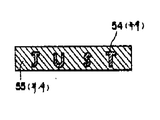
제4도는 본 발명의 일실시예에 있어서의 동조상태가 최적이 아닌 경우의 화면의 표시상태를 표시한 도면.4 is a diagram showing a display state of a screen when the tuning state in one embodiment of the present invention is not optimal.
제5도는 제4도의 동조상태가 최적인 경우의 표시를 나타낸 도면.FIG. 5 is a diagram showing the display when the tuning condition of FIG. 4 is optimal; FIG.
제6도는 본 발명의 다른 실시예를 표시한 회로도.6 is a circuit diagram showing another embodiment of the present invention.
제7도는 제6도의 각 비교기의 입출력전압 파형도.7 is an input / output voltage waveform diagram of each comparator of FIG.
제8도는 제6도의 장치에 의한 동조표시예를 나타낸 도면.8 shows an example of tuning display by the apparatus of FIG.
제9도는 본 발명의 제3의 실시예를 표시한 회로도.9 is a circuit diagram showing a third embodiment of the present invention.
제10도는 제9도의 장치에 의한 동조표시기의 일례를 나타낸 도면.FIG. 10 shows an example of a tuning indicator by the apparatus of FIG.
* 도면의 주요부분에 대한 부호의 설명* Explanation of symbols for main parts of the drawings
4 : 반송파증폭용 트랜지스터 7 : 정류용 다이오우드4: carrier amplifier transistor 7: rectifier diode
12, 14, 47, 63, 64 : 비교기 16 : 톱니파발생용 트랜지스터12, 14, 47, 63, 64: comparator 16: sawtooth wave generation transistor
20 : 논리곱게이트 21, 37 : 녹색음극 드라이브용 트랜지스터20: AND
22, 43 : 적색음극 드라이브용 트랜지스터22, 43: transistor for red cathode drive
23 : 청색음극 드라이브용 트랜지스터23: transistor for blue cathode drive
30 : 음극선관 32, 60 : 문자발생장치30:
33, 61, 71 : 마이크로컴퓨우터 34 : 문자출력단자33, 61, 71: microcomputer 34: character output terminal
35 : 배경출력단자 39 : 영상신호블랭킹용 트랜지스터35: background output terminal 39: video signal blanking transistor
42 : 배경출력제어용 트랜지스터 52 : 스위칭 트랜지스터42: background output control transistor 52: switching transistor
54 : 문자 55, 55' : 배경54:
62 : 주파수 판별회로62: frequency discrimination circuit
본 발명은, 컬러텔레비젼수상기의 음극선관의 화면에 동조상태를 표시하는 동조표시장치에 관한 것이다.The present invention relates to a tuning display for displaying a tuning state on a screen of a cathode ray tube of a color television receiver.
종래의 컬러텔레비젼수상기에 있어서의 동조표시장치는, 제1도에 표시한 바와같이 구성되어 있었다. 제1도에 있어서, (1)은 콘덴서이며, 그 일단에는 영상중간주파신호(a)가 공급되고 있다.The tuning display device in the conventional color television receiver was constructed as shown in FIG. In Fig. 1,
콘덴서(1)의 타단에는 바이어스설정용 저항기(2) 및 (3)과 반송파증폭용 트랜지스터(4)의 베이스가 접속되어 있다. (4)는 반송파증폭용 트랜지스터로서, 그 이미터는 접지되고, 콜렉터는 서로 병렬로 접속된 코일(5)과 콘덴서(6)를 개재해서 전원(+B)에 접속되어 있다.The other end of the
그리고, 정류용다이오우드(7)의 양극이 코일(5)의 중간탭에 접속되어 있으며, 그 음극은 일단이 접지된 평활용콘덴서(8)의 타단에 접속된 후에, 저항기(9)를 개재해서 트랜지스터(10)의 베이스에 접속되어 있다. 트랜지스터(10)의 이미터는 저항기(11)를 개재해서 접지됨과 동시에 트랜지스터(12)의 마이너스 입력단자에 접속되고, 콜렉터는 저항기(13)를 개재해서 전원(+B)에 접속됨과 동시에 비교기(14)의 플러스입력단자에 접속되어 있다. 또한, 트랜지스터(10)의 이미터와 콜렉터는 저항기(15)를 개재해서 서로 접속되어 있다. 한편, (16)은 톱니파발생용 트랜지스터로서, 그 베이스에는 저항기(17)를 개재해서 정극성의 수평플라이백펄스(b)가 공급되고 있다. 상기 톱니파발생용 트랜지스터(16)의 이미터는 접지되고, 콜렉터는 저항기(18)를 개재해서 전원(+B)에 접소됨과 동시에 콘덴서(19)를 개재해서 접지되고, 또 비교기(12)의 플러스입력단자와 비교기(14)의 마이너스 입력단자에 접속되고 있다. 비교기(12) 및 (14)의 각 출력단자는 논리곱게이트(20)의 입력단자에 각각 접속되어 있다. 또, (21)은 녹색음극 드라이브용 트랜지스터, (22)는 적색음극 드라이브용 트랜지스터, (23)은 청색음극 드라이브용 트랜지스터로서, 각각의 베이스에 녹색, 적색 및 청색의 영상신호(c)(d) 및 (e)가 각각 공급되고 있다. 상기 각 드라이브용 트랜지스터(21)(22)(23)의 각각의 이미터는 각각 저항기 (24)(25) 및 (26)을 개재해서 접지되고, 각각의 콜렉터는 각각 저항기(27)(28) 및 (29)를 개재해서 전원(+B)에 접속됨과 동시에 음극선관(30)의 녹색음극, 적색음극 및 청색음극에 각각 접속되어 있다. 그리고, 논리곱게이트(20)의 출력단자가 다이오우드(31)를 개재해서 녹색음극 드라이브용 트랜지스터(21)의 베이스에 접속되고 있다.After the anode of the rectifying diode 7 is connected to the middle tab of the coil 5, the cathode is connected to the other end of the smoothing capacitor 8 having one end grounded, and then through the resistor 9. It is connected to the base of the transistor 10. The emitter of the transistor 10 is grounded via a resistor 11 and connected to the negative input terminal of the
다음에, 본 실시예의 동작을 제2도에 따라서 설명한다. 콘덴서(1)의 일단에 인가된 영상중간주파신호(a)는, 반송파증폭용트랜지스터(4)로 증폭됨과 동시에 영상중간주파신호(a)의 반송파성분의 주파수로 공진하도록 선택된 코일(5)과 콘덴서(6)에 의해서 반송파성분이 꺼내어진다. 반송파성분은 검파수단인 정류용다이오우드(7)와 평활용 콘덴서(8)에 의해서 검파되어 직류전압으로서 꺼내어지며, 최적동조점에서 그 전압이 가장 높아지게 된다. 이 직류전압이 저항기(9)를 개재해서 트랜지스터(10)의 베이스에 인가되면, 트랜지스터(10)의 이미터전압(f)은 베이스전압이 높아지면 높아지고, 콜렉터전압(g)은 베이스전압이 높아지면 낮아진다. 한편, 저항기(17)의 일단에 인가된 수평 플라이백펄스(b)는, 톱니파발생용 트랜지스터(16)와 저항기(18)와 콘덴서(19)에 의해서 톱니파전압(h)으로 변환된다. 그리고, 비교기(12)의 마이너스 입력단자에 트랜지스터(10)의 이미터전압(f), 플러스입력단자에 톱니파전압(h)이 입력된다. 또 비교기(14)의 플러스입력단자에 트랜지스터(10)의 콜렉터전압(g), 마이너스 입력단자에 톱니파전압(h)이 입력되어서, 비교기(12) 및 (14)의 각 출력단자로부터 제2도에 표시한 바와같은 펄스형상의 출력전압(i) 및 (j)이 출력된다. 또한 이 출력전압(i) 및 (j)이 논리곱게이트(20)에 입력되어서, 제2도에 표시한 바와같은 펄스형상의 출력전압(k)이 논리곱게이트(20)로부터 출력된다. 또한, 제2도에서 명백한 바와같이, 동조상태가 최적 동조점에 근접해서 트랜지스터(10)의 이미터전압(f)이 상승하고, 콜렉터전압(g)이 하강하면, 논리곱게이트(20)의 출력전압(k)의 펄스폭은 좁아진다. 이와같이, 동조상태에 따라서 펄스폭이 변화하는 논리곱게이트(20)의 출력전압(k)이, 다이오우드(31)를 개재해서 녹색음극 드라이브용 트랜지스터(21)의 베이스에 공급되고, 녹색영상신호와 혼합되어서 음극선관(30)으로 입력된다. 여기서, 논리곱게이트(20)의 출력전압(k)은 수평주사와 동기된 펄스신호임으로, 그 펄스폭에 따른 폭의 세로한줄의 녹색띠로서 음극선관(30)의 화면상에 텔리비젼방송의 영상과 함께 비치게 된다. 따라서, 이 녹색의 띠는 동조상태에 따라서 그 폭이 변화하고, 최적동조점에서 가장 폭이 좁아진다.Next, the operation of this embodiment will be described with reference to FIG. The image intermediate frequency signal a applied to one end of the
그러나, 상기의 종래예에서는 다음과 같은 결점이 있다. 첫째로, 화면에 비치게되는 텔레비젼방송의 영상에 따라서는 녹색의 띠는 보기 힘들어서, 그 폭을 판단하는 것이 곤란하다는 결점이다. 둘째로, 사용자가 화면상의 녹색의 띠를 보는 것만 가지고는 동조상태의 최적여부를 판단할 수 없으며, 컬러텔레비젼수상기의 조정손잡이를 조작하여, 동조상태를 변화시켜서 녹색띠의 폭을 변화시켜 보지않고서는 동조상태를 명확하게 알수가 없다고 하는 문제이다. 이 때문에, 사용자는 동조상태가 최적인데도 불구하고, 그것을 확인하기 위해서 조정손잡이를 조작해서 동조상태를 한번 최적동조점으로부터 벗어나게 하여, 재차 최적동조점에 맞춘다고 하는 불필요한 조작을 행하였었다.However, the above conventional example has the following drawbacks. First, the green band is difficult to see depending on the image of the television broadcast reflected on the screen, and it is difficult to judge the width thereof. Secondly, the user cannot judge the optimal condition only by looking at the green band on the screen, and operate the adjustment knob of the color television receiver to change the tuning state without changing the width of the green band. The problem is that the state of synchronization is not clearly known. For this reason, even though the tuning condition is optimal, the user has made an unnecessary operation of operating the adjusting knob to check the tuning condition and deviating the tuning condition from the optimum tuning point once again to set the optimum tuning point again.
본 발명은, 상기 종래예의 결점을 감안하여 이루어진 것으로서, 화면상의 표시가 보기쉽고, 또 그 화면을 보기만해도 동조상태의 최적여부를 판단할수 있는 동조표시장치를 제공하는 것이다.SUMMARY OF THE INVENTION The present invention has been made in view of the drawbacks of the above-described prior art, and provides a tuning display device that is easy to see on the screen and that can determine whether the tuning is optimal even by viewing the screen.
상기 목적을 달성하기 위하여, 본 발명은, 입력 텔레비젼 신호에 의거해서 영상을 표시하는 음극선관을 사용한 표시장치의 화면상에 문자 혹은 도형을 나타내는 문자출력신호와 상기 문자 혹은 도형의 주위를 소정의 영역으로 둘러싸는 배경을 나타내는 배경출력신호를 발생하는 문자발생수단과, 입력영상 중간주파신호로부터의 반송파성분을 검파해서 동조도에 따른 검파출력을 발생하는 검파수단과, 상기 검파수단으로부터의 검파출력과 기준신호를 입력으로하고 상기 검파출력과 기준신호를 비교하여 동조도에 따른 비교출력을 발생하는 비교수단과, 상기 비교수단으로부터의 비교출력을 입력으로하여 상기 검파출력레벨이 기준신호 레벨보다 작은것을 표시하는 비교출력이 입력되었을때는 상기 문자발생수단으로부터 출력되는 상기 배경출력신호로써 상기 배경의 일부는 제1의 색으로 기타의 부분은 제2의 색으로 표시되도록 상기 문자발생수단을 제어하고, 상기 검파출력레벨이 기준신호레벨 이상인 것을 표시하는 비교출력이 입력되었을때는 상기 배경출력신호로써 상기 제1 또는 제2의 색의 어느한쪽의 색으로 표시되도록 문자발생수단을 제어하는 제어수단을 구비한 것을 특징으로 한다.In order to achieve the above object, the present invention provides a predetermined area around a character output signal and a character output signal representing a character or a figure on a screen of a display device using a cathode ray tube for displaying an image based on an input television signal. A character generating means for generating a background output signal representing a background surrounded by a signal, a detecting means for detecting a carrier component from an input image intermediate frequency signal, and generating a detection output according to the tuning intensity, a detection output from the detecting means, A comparison means for inputting a reference signal and comparing the detection output with the reference signal to generate a comparison output according to the illumination intensity; and a comparison output from the comparison means as input, wherein the detection output level is smaller than the reference signal level. The background output outputted from the character generating means when a comparison output to be displayed is inputted The character generating means is controlled to display a part of the background as a first color and a part of a second color as a second arc, and when a comparison output indicating that the detection output level is equal to or greater than a reference signal level is inputted. And a control means for controlling the character generating means to be displayed as one of the first and second colors as the background output signal.
또, 보다더 알기 쉽게하기 위해서, 문자 혹은 도형의 위치를 바꾸어, 좌우로 움직이게 하므로서, 사용자에게 조작해야 할 방향을 즉시 알 수 있게 한 것이다.Moreover, in order to make it easier to understand, the position of a character or a figure is changed and it moves to the left and right, and the user can immediately know the direction which should be operated.
또, 보다 더 알기 쉽게하기 위해서, 상기 중간주파신호를 주파수 판별회로에 의해서 FM 검파한 신호를 꺼내서, 이 신호로 최적 동조점에서 높은쪽으로 벗어나 있는지, 낮은쪽으로 벗어나 있는지를 판별하고, 이 판별출력으로 문자 혹은 도형의 종류까지도 바꾸도록 한 것이다.In order to make it easier to understand, the FM signal detected by the frequency discriminating circuit is taken out to determine whether the intermediate frequency signal deviates from the optimum tuning point to the high side or the low side. It even changed the type of characters or figures.
이하, 도면에 의해서 본 발명이 실시예를 상세하게 설명한다. 제3도는, 본 발명의 제1실시예의 구성을 표시한 도면으로서, 제1도와 동일부호의 것은 동일한 것을 표시하고 있다. 또 제3도에 있어서, (32)는 문자 발생수단, 즉 문자발생장치로서, 제어용의 마이크로컴퓨터(33)가 접속된다. 상기 문자발생장치(32)는 수평플라이백펄스(b)와 수직펄스(l)가 입력되어 있어서, 문자를 표시하기 위한 정극성의 펄스형상의 문자출력신호를 출력하는 문자출력단자(34)와, 배경을 표시하기 위한 정극성의 펄스형상의 배경출력신호를 출력하는 배경출력단자(35)를 구비하고 있다. 이 문자발생장치(32)의 문자출력단자(34)는, 저항기(36)를 개재해서 녹색음극 드라이브용 트랜지스터(21)와 이미터 및 콜렉터가 공통으로 된 다른 녹색음극 드라이브용 트랜지스터(37)의 베이스에 접속된다. 한편, 상기 문자발생장치(32)의 배경출력단자(35)는, 저항기(38)를 개재해서 이미터가 접지된 영상신호 블랭킹(blanking)용 트랜지스터(39)의 베이스에 접속된다. 또, 상기 배경출력단자(35)는 저항기(40)를 개재한 다음, 이미터가 접지되고, 동시에 베이스가 저항기(41)를 개재해서 논리곱게이트(20)의 출력단자에 접속된 배경출력 제어용트랜지스터(42)의 콜렉터와, 적색음극드라이브용의 트랜지스터(22)와 이미터 및 콜렉터가 공통으로된 다른 적색음극 드라이브용 트랜지스터(43)의 베이스에 접속되어 있다. 또한 영상 신호블랭킹용 트랜지스터(39)의 콜렉터에는 각각의 양극이 녹색, 적색 및 청색의 음극드라이브용 트랜지스터(21)(22) 및 (23)의 베이스에 각각 접속된 다이오우드(44)(45) 및 (46)의 각 음극이 공통으로 접속되어 있다. 또 (47)은 최적 동조점판별용의 비교기로서, 그 플러스입력단자가 다이오우드(7)의 음극에 접속되며, 동시에 마이너스 입력단자가 기준전압설정용의 가변저항기(48)의 센터단자에 접속되어 있다.EMBODIMENT OF THE INVENTION Hereinafter, an Example demonstrates this invention in detail by drawing. 3 is a diagram showing the configuration of the first embodiment of the present invention, in which the same reference numerals as those in FIG. In Fig. 3,
이 가변저항기(48)의 일단은 저항기(49)를 개재해서 전원(+B)에 접속되고, 타단은 저항기(50)를 개재해서 접지되어 있다. 비교기(47)의 출력단자는 저항기(51)를 개재한 다음, 이미터가 접지된 스위칭 트랜지스터(52)의 베이스에 접속되어 있다. 또한 스위칭트랜지스터(52)의 콜렉터는 배경출력제어용트랜지스터(42)의 베이스에 접속되어 있다.One end of the
다음에 본 실시예의 동작을 제4도, 제5도를 이용해서 설명한다. 문자발생장치(32)는, 마이크로컴퓨우터(33)로 제어되어서, 제4도에 표시한 바와같이 텔레비젼방송의 영상이 비춰지고 있는 음극선관(30)의 화면(53)상의 소정위치에, 예를들면 "JUST"와 같은 문자(54)와, 그 문자(54)를 네모꼴로 둘러싼 배경(55)를 표시하도록 문자출력단자(34) 및 배경출력단자(35)로부터 각각 문자출력신호 및 배경출력신호를 출력하고 있다. 여기서, 문자발생장치(32)에 입력된 수평플라이백펄스(b)와 수직펄스(l)는 문자(54) 및 배경(55)의 표시위치를 설정할 때에 이용되고 있다. 이 문자출력단자(34)로부터 출력된 문자출력신호는, 저항기(36)를 개재해서 녹색음극 드라이브용 트랜지스터(37)를 구동해서, 제4도와 같이 화면(53)에 녹색의 "JUST"라는 문자(54)를 표시하게 한다. 또 배경출력단자(35)로부터 출력된 배경출력신호는, 저항기(40)를 개재해서 적색음극드라이브용 트랜지스터(43)를 구동해서, 제4도와 같이 화면(53)에 녹색의 문자를 네모꼴로 둘러싼 배경(55)을 적색으로 표시하게 하는 동시에, 저항기(38)를 개재해서 영상신호 블랭킹용 트랜지스터(39)를 도통시켜서, 배경출력신호가 출력되고 있는 동안에는 영상신호를 블랭킹시키고 있다.Next, the operation of this embodiment will be described with reference to FIG. 4 and FIG. The
이때, 비교수단, 즉 최적동조점 판별용의 비교기(47)는 그 마이너스 입력단자에 가변저항기(48)에 의해서 설정된 기준전압이 공급되고, 플러스 입력단자에 다이오우드(7)로부터의 영상중간주파수신호로부터 반송파성분을 꺼내서, 증폭 및 검파한 동조도에 대응하는 신호가 공급되고 있으며, 이 기준전압은 최적동조점일때에 출력이 "하이레벨"로 되도록 설정되어 있다. 따라서, 동조상태가 최적이 아닌 경우에는, 비교기(47)로부터 "로우레벨"이 출력되어 스위칭트랜지스터(52)가 차단되므로, 논리곱게이트(20)로부터의 펄스형상의 출력전압(k)에 의해서 배경출력제어용트랜지스터(42)가 도통, 차단을 반복하여, 배경출력신호를 논리곱게이트(20)의 출력전압(k)의 펄스가 나오고 있는 동안만 차단하고, 제4도에 표시한 바와같이 적색의 배경(55)일부를 흑색의 배경(55')으로 바꾸어 표시한다. 이 흑색의 배경(55')의 가로폭은 논리곱게이트(20)의 출력전압(k)의 펄스폭에 비례하기 때문에 동조상태가 최적 동조점으로부터 떨어져 있으면 넓고, 최적 동조점에 가까와짐에 따라서 좁아진다. 또한, 흑색의 배경(55')의 가로폭이 가장 넓어졌을 경우에도 적색의 배경(55)을 넘지않게 적색의 배경(55)의 가로폭이 설정되어 있다. 또 최적 동조점이 되었을 경우에는, 최적 동조점 판별용의 비교기(47)의 출력이 "하이레벨"로 되어, 스위칭트랜지스터(52)를 도통시켜서 배경출력제어용트랜지스터(42)를 차단한다. 이 때문에, 적색음극드라이브용 트랜지스터(43)는 문자발생장치(32)의 배경출력단자(35)로부터 차단됨이 없이 공급된 배경출력신호에 의해서 구동되어, 제5도에 표시한 바와같이 흑색부분이 없는 완전한 적색의 배경(55)을 표시한다. 또한, 이 표시동작은, 동조조작시에 그 지령이 마이크로컴퓨우터(33)에 가해져서 표시동작을 행한다.At this time, the comparator 47, that is, the comparator 47 for determining the optimum tuning point, is supplied with the reference voltage set by the
이와 같이해서, 동조상태가 최적이 아닌 경우에는, 적색의 배경(55) 일부를 그 동조도에 따른 폭으로 흑색의 배경(55')으로 바꾸어 표시하고, 최적 동조점이 되면 적색의 배경(55')을 완전한 형태로 표시하므로, 사용자는 그 표시를 본것만으로도 동조상태를 정확하게 판단할 수 있다. 또한, 실제의 문자(54)의 색은 배경이 흑색부분에서는 녹색이지만, 배경이 적색일때는, 녹색과 적색이 섞여서 황색의 문자로 보인다.In this manner, when the tuning condition is not optimal, a part of the
또한, 상기 실시예에서는, 문자와 그 배경에 의해서 표시를 행하고 있었으나, 문자대신에 도형을 표시하여, 도형과 그 배경에 의해서 동조상태를 표시해도 된다.In the above embodiment, although the display is performed by the characters and the background, the figures may be displayed instead of the characters, and the synchronized state may be displayed by the figures and the background.
제6도에 본 발명의 제2실시예를 표시한다. 제6도에 있어서 제3도와 동일부호의 것은 동일한 것을 표시하고 있다. 제6도에 표시한 장치는, 중간주파신호를 주파수판별회로에 의해서 FM검파한 신호를 꺼내고, 이 신호로 최적 동조점으로부터 높은쪽으로 벗어나 있는지, 낮은쪽으로 벗어나 있는지를 판별하여, 배경내의 문자 혹은 도형의 종류를 바꾸도록 한 것이다.6 shows a second embodiment of the present invention. In FIG. 6, the same code | symbol as FIG. 3 shows the same thing. The apparatus shown in Fig. 6 extracts the FM-detected signal by the frequency discrimination circuit, and determines whether the signal is out of the optimum tuning point higher or lower by using the frequency discrimination circuit, so that the character or figure in the background To change the type of.
제6도에 대해서 설명한다. 제6도에 있어서, (60)은 문자발생장치, (61)은 이 문자발생장치(60)를 제어하는 제어수단, 즉 마이크로컴퓨우터이다. 비교기(47)의 플러스단자는 다이오우드(7)의 음극에 접속되고, 마이너스 단자는 기준전압설정용의 볼륨(48)의 센터단자에 접속된다. 비교기(47)의 출력은 마이크로컴퓨우터(61)의 입력단자에 접속된다. (62)는 주파수 판별회로로서 입력단자는 영상중간주파증폭회로 도시하지 않음)에 접속되고, 출력단자는 튜우너(도시하지 않음)의 AFT단자에 접속되어 AFT동작을 행함과 동시에 비교기(63)(64)의 각 플러스 단자에도 접속된다. 이 전압을 AFT전압이라 부르며, 통상 0~12V사이에 있고, 최적 동조점에서는 6V가 된다. 비교기(63)의 마이너스 단자와 비교기(64)의 마이너스단자에는 기준이 되는 전압을 주기 위해서 전원으로부터 접지에 저항(65)(66)(67)이 직렬로 접속되어 있으며, 저항(65)과 (66)과의 교차점은 비교기(63)의 마이너스단자에, 저항(66)과 (67)과의 교차점은 비교기(64)의 마이너스단자에 접속된다. 이와 같이해서 얻어지는 비교기(63)(64)의 기준전압은, 비교기(63)의 것은 6V보다 높게 약 8V로, 비교기(64)의 것은 6V보다 낮게 약 4V로 설정되어 있다.6 will be described. In Fig. 6, reference numeral 60 denotes a character generator, and 61 denotes control means for controlling the character generator 60, that is, a microcomputer. The positive terminal of the comparator 47 is connected to the negative electrode of the diode 7, and the negative terminal is connected to the center terminal of the
비교기(63)와 (64)의 출력은 마이크로컴퓨우터(61)의 입력단자에 접속된다.The outputs of the comparators 63 and 64 are connected to the input terminals of the microcomputer 61.
다음에, 이 회로의 동작을 설명한다. 마이크로컴퓨우터(61)는 문자 발생장치(60)를 제어해서 음극선관(30)상의 소정위치에 문자를 표시한다.Next, the operation of this circuit will be described. The microcomputer 61 controls the character generator 60 to display characters at predetermined positions on the cathode ray tube 30.
수평펄스(b)와 수직펄스(l)는 이 표시의 위치결정에 필요하다. 비교기(47)의 플러스단자에는 중간주파수의 반송파성분을 검파한 신호를 가하고, 마이너스단자에는 기준이되는 전압을 가한다. 기준이 되는 전압은 비교기(47)의 플러스단자에 가해지는 전압이 최적동조점부근일때에, 기준전압보다 높아지도록 선정한다. 비교기(47)의 출력은 마이크로컴퓨우터(61)의 입력단자에 가하고, 동조점부근인지 아닌지의 정보를 "1"과 "0"의 신호로 전달한다. 주파수판별회로(62)는 영상중간주파수신호를 입력해서, 이것을 FM검파하여 AFT동작에 필요한 AFT전압을 만드는 회로로서 일반적인 컬러텔레비젼수상기에는 모두 구비되어 있다. 이 출력전압을 비교기(63)(64)의 플러스단자에 가하고, 비교기(63)의 마이너스단자에는 8V, 비교기(64)의 마이너스 단자에는 4V의 기준전압을 부여해둔다. 비교기(63)(64)의 출력은 마이크로컴퓨우터(61)의 입력단자에 가한다. 그렇게 하므로서 AFT전압이 0~4V인지 4~8V인지, 혹은 8V이상인지의 정보를 "1"과 "0"의 신호로 마이크로컴퓨우터(61)에 전달할 수 있다.The horizontal pulse b and the vertical pulse l are necessary for positioning of this display. A signal obtained by detecting a carrier component of intermediate frequency is applied to the plus terminal of the comparator 47, and a reference voltage is applied to the minus terminal. The reference voltage is selected to be higher than the reference voltage when the voltage applied to the plus terminal of the comparator 47 is near the optimum tuning point. The output of the comparator 47 is applied to the input terminal of the microcomputer 61, and transmits information of whether or not near the tuning point as a signal of "1" and "0". The frequency discrimination circuit 62 is a circuit for inputting an image intermediate frequency signal, FM detection thereof, and making an AFT voltage necessary for AFT operation, which is provided in a general color television receiver. The output voltage is applied to the positive terminals of the comparators 63 and 64, and a reference voltage of 8 V is applied to the negative terminal of the comparator 63 and 4 V to the negative terminal of the comparator 64. The outputs of the comparators 63 and 64 are applied to the input terminals of the microcomputer 61. In doing so, information on whether the AFT voltage is 0 to 4 V, 4 to 8 V, or 8 V or more can be transmitted to the microcomputer 61 as signals of "1" and "0".
제7도는 동조점부근에서의 마이크로컴퓨우터(61)에 가해지는 신호와, 그 신호를 만들기 위한 각 비교기(47)(63)(64)의 입력신호를 가로축에 주파수를 잡아 표시한 것이다. 영역(c)이 최적동조점이고, (a)(b)는 그것보다 낮은 영역, (d)(e)는 그것보다 높은영역이다. (G)는 비교기(47)의 플러스단자에 가해지는 전압, 파선은 마이너스 단자에 가해지는 기준전압, (H)는 비교기(47)의 출력전압, (I)는 비교기(63)(64)의 플러스단자에 가해지는 AFT전압, 여기서 위의 파선은 비교기(63)의 마이너스단자에 가해지는 기준전압, 아래의 파선은 비교기(64)의 마이너스단자에 가해지는 기준전압이다. 또 (J)는 비교기(63)의 출력전압, (k)는 비교기(64)의 출력전압이다. 이 도면에서 (a)~(e) 각 영역의 정보는 (H)(J)(K)의 "1"과 "0"의 신호로 제1표와 같이 마이크로컴퓨우터(61)에 전달된다.7 shows the signal applied to the microcomputer 61 near the tuning point and the input signal of each of the comparators 47, 63 and 64 for producing the signal at a horizontal axis. Area (c) is the optimum tuning point, (a) and (b) are lower areas, and (d) and (e) are higher areas. (G) is the voltage applied to the positive terminal of the comparator 47, the broken line is the reference voltage applied to the negative terminal, (H) is the output voltage of the comparator 47, (I) is the voltage of the comparator 63, 64 The AFT voltage applied to the positive terminal, where the broken line above is the reference voltage applied to the negative terminal of the comparator 63, and the broken line below is the reference voltage applied to the negative terminal of the comparator 64. (J) is the output voltage of the comparator 63, and (k) is the output voltage of the comparator 64. In this figure, the information of each region (a) to (e) is transmitted to the microcomputer 61 as the first table as signals of "1" and "0" of (H) (J) (K).
[제1표][Table 1]

마이크로컴퓨우터(61)는 수단(61a)으로 상기 신호를 판별하여, 수단(61b)을 통해서 문자발생장치(60)를 제어해서 음극선관(30)에 표시해야 할 문자를 바꾼다. 각 입력정보에 대한 표시문자는 일례로서 예를들면 제3표와 같다.The microcomputer 61 discriminates the signal by means 61a, controls the character generator 60 through the means 61b, and changes the characters to be displayed on the cathode ray tube 30. Display characters for the respective input information are shown in Table 3 as an example.
[제2표][Table 2]

(주)-표는 1과 0의 어느쪽이라도 된다는 것을 표시한다. 제1표와 제2표로부터 제1표의 각 영역에서의 표시문자는 제3표와 같이된다는 것을 쉽게 이해할 수 있다.(Note)-indicates that either 1 or 0 may be used. It can be easily understood that the display characters in the respective areas of the first table from the first and second tables become like the third table.
[제3표][Table 3]

이와같이 동조상태를 배경(55)의 색을 바꿈과 동시에 문자로 표시하게 하므로서 사용자는 현재상태를 용이하게 파악할 수 있고, 또 약간 벗어나 있을때에는 동조손잡이를 어떻게 돌리면 되는가를 텔레비젼이 가르쳐주기 때문에 동조시키기가 쉽다. 이 예에서는 동조손잡이로 동조조작하는 것을 가정하고 있기 때문에, "TURN·RIGHT" "TURN·LEFT"의 문자를 내고 있으나, 업 혹은 다운의 누름단추로 동조조작하는 선극시스템의 경우에는, 예를들면 "PUSH·UP" "PUSH·DOWN"등의 적당한 문자를 사용하면 된다. 제8도에는 본 발명에 의해서 동조조작시에 음극선관(30)에 비춰내는 문자의 예를 표시한다. 제8(a)도는 동조가 완전히 벗어나 있을때, 제3표에 있어서의 (a)(e)의 상태의 음극선관에 비친문자, 제8(b)도는 제3표 (b)의 상태, 제8(c)도는 제3표 (c)의 상태, 제8(d)도는 제3표 (d)의 각 상태에서의 표시문자를 나타내고 있다. 또한, 이 때의 변형은 도시한 바와같이 변화한다.In this way, the user can easily grasp the current state by changing the color of the
또한, 상기 실시예에 있어서는, 알파벳을 사용해서 설명했으나, 일본어 기타의 문자를 사용해도 지장이 없다. 또, 상기 실시예에서는 동조상태(TUNED)와 비동조상태(DETUNED) 및 동조조작해야 할 방향(TURN·RIGHT, TURN·LEFT)을 표시하도록 하고 있으나, 동조상태와 비동조상태를 나타내는 문자만 표시하도록 해도 된다. 또, 표시는 문자가 아니라, 도형으로 나타내도록 해도 되며, 예를들면 동조좍해야 할 방향은 화살표로 표시하도록 해도 된다.In addition, in the said Example, although demonstrated using the alphabet, even if it uses the Japanese and other characters, it does not interfere. Further, in the above embodiment, the tuned state (TUNED) and the non-tuned state (DETUNED) and the direction to be tuned (TURN, RIGHT, TURN, LEFT) are displayed, but only the characters indicating the tuned state and the non-tuned state are displayed. You may do so. In addition, the display may be represented by a figure instead of a character, and for example, the direction to be synchronized may be displayed by an arrow.
다음에 본 발명의 제3실시예를 도면을 사용해서 설명한다. 제6도의 마이크로컴퓨우터수단(61)의 기능을 바꾸어서 (71)로 한 것을 제9도에 표시한다. 제6도와 다른점은 마이크로컴퓨우터(71)의 기능블록의 문자종류, 위치변경수단(71b)이며, 제6도의 표시문자변경수단(61b)에 대해서, 이 쪽은 문자의 종류와 위치도 변경하도록 하고 있다. 또한, 신호판별수단(71a)은 제6도의 수단(61a)과 같은 기능을 수행한다. 동작은 제6도의 설명과 거의 같으나 단지 제6도의 설명에서는 동조가 벗어나 있어서 오른쪽으로 돌릴 필요가 있을때에 문자가 "TURN·RIGHT"라고 나올뿐이였으나, 이쪽은 "TURN·RIGHT"라고 나오고, 또 그 문자가 오른쪽으로 움직여 간다는 것이다. 그 모양을 제10도에 표시했다. 이 도면에서는 문자만 표시하고 있으며 배경은 생략되어 있다. 위의 도면에서 시간이 지나면 아래도면이 된다. 즉 시간의 경과와 함께 문자가 이동한다는 것을 설명하고 있다. 이 지시에 따라서, 사용자는 동조손잡이를 회전시키면 되고, 이 조작에 의해서 최적동조 상태가 되면, 문자는 "TURN·RIGHT" 혹은 "TURN·LEFT"로부터 "TUNED"로 변화하고, 배경(55)로 흑색이 없어져서 적색으로 통일된다.Next, a third embodiment of the present invention will be described with reference to the drawings. FIG. 9 shows that the function of the microcomputer means 61 in FIG. 6 is changed to 71. FIG. 6 is different from the character type of the functional block of the microcomputer 71 and the position changing means 71b. For the display character changing means 61b of FIG. 6, this also changes the type and position of the character. I'm trying to. Further, the signal discriminating means 71a performs the same function as the means 61a of FIG. The operation is almost the same as that of FIG. 6, but in the explanation of FIG. 6, when the tuning is out of sync and it needs to be turned to the right, the letters appear as "TURN RIGHT", but this is "TURN RIGHT". The text moves to the right. The shape is shown in FIG. In this figure, only the characters are displayed and the background is omitted. In the above drawing, the time becomes the bottom view over time. In other words, the characters move with the passage of time. According to this instruction, the user only needs to rotate the tuning knob, and when the optimum tuning state is achieved by this operation, the character changes from "TURN RIGHT" or "TURN LEFT" to "TUNED" and changes to the
이상 설명한 바와같이, 본 발명은 입력 텔레비젼 신호에 의거해서 영상을 표시하는 음극선관을 사용한 표시장치의 화면상에 문자 혹은 도형을 나타내는 문자 출력신호와 상기 문자 혹은 도형의 주위를 소정의 영역으로 둘러싸는 배경을 나타내는 배경출력신호를 발생하는 문자발생수단과, 입력영상 중간주파수신호로부터의 반송파 성분을 검파해서 동조도에 따른 검파출력을 발생하는 검파수단과, 상기 검파수단으로부터의 검파출력과 기준신호를 입력으로 하고 상기 검파출력과 기준신호를 비교하여 동조도에 따른 비교출력을 발생하는 비교수단과, 상기 비교수단으로부터의 비교출력을 입력으로 하여 상기 검파출력레벨이 기준 신호레벨보다 작은 것을 표시하는 비교출력이 입력되었을때는 상기 문자발생수단으로부터의 출력되는 상기 배경출력신호로써 상기 배경의 일부는 제1의 색으로 기타의 부분은 제2의 색으로 표시되도록 상기 문자발생수단을 제어하고, 상기 검파출력레벨이 기준신호레벨 이상인 것을 표시하는 비교출력이 입력되었을때는 상기 배경출력신호로써 상기 제1 또는 제2의 색의 어느 한쪽의 색으로 표시되도록 문자발생수단을 제어하는 제어수단을 구비한 것을 특징으로 하므로써 문자 혹은 도형과 그 주위의 색이 다른 배경과의 휘도에 의해서 표시가 보기쉽고, 또한 사용자가 그 표시를 본 것만으로 동조상태를 정확하게 판단할 수 있다. 또한 문자로서 상표나 회사명등을 표시하므로서 선전도 되는 등의 효과가 있는 것이다. 또, 배경의 색과 함께 문자 혹은 도형의 색, 종류까지도 바꾸도록 하므로서, 보다 명확하게 동조상태를 표시할 수 있다. 또한 문자 혹은 도형의 위치를 바꾸고, 좌우로 움직이므로서 사용자에게 조작해야 할 방향을 용이하게 알게 할 수 있다.As described above, the present invention surrounds a character output signal representing a character or a figure on a screen of a display device using a cathode ray tube displaying an image based on an input television signal, and a predetermined area around the character or figure. Character generating means for generating a background output signal representing the background, Detection means for detecting a carrier component from an input image intermediate frequency signal, and for generating a detection output according to the roughness, Detection output from the detection means and a reference signal A comparison means for making an input and comparing the detection output with a reference signal to generate a comparison output according to the illumination intensity, and a comparison indicating that the detection output level is smaller than the reference signal level by inputting the comparison output from the comparison means. The background output outputted from the character generating means when an output is inputted The character generating means is controlled to display a part of the background as a first color and a part of a second color as a second arc, and when a comparison output indicating that the detection output level is equal to or greater than a reference signal level is inputted. And a control means for controlling the character generating means to be displayed as one of the first and second colors as the background output signal. The display is easy to see, and the user can judge the tuning state accurately just by looking at the display. In addition, it is effective in displaying a trademark or a company name as a letter. In addition, the synchronization state can be displayed more clearly by changing the color and type of the character or figure together with the background color. In addition, by changing the position of the character or figure, and moving from side to side, the user can easily know the direction to operate.
Claims (4)
Applications Claiming Priority (2)
| Application Number | Priority Date | Filing Date | Title |
|---|---|---|---|
| JP58159959A JPS6052175A (en) | 1983-08-31 | 1983-08-31 | Tuning display device |
| JP58-159959 | 1983-08-31 |
Publications (2)
| Publication Number | Publication Date |
|---|---|
| KR850002194A KR850002194A (en) | 1985-05-06 |
| KR890005238B1 true KR890005238B1 (en) | 1989-12-18 |
Family
ID=15704903
Family Applications (1)
| Application Number | Title | Priority Date | Filing Date |
|---|---|---|---|
| KR1019840005005A KR890005238B1 (en) | 1983-08-31 | 1984-08-20 | Tunning display apparatus |
Country Status (2)
| Country | Link |
|---|---|
| JP (1) | JPS6052175A (en) |
| KR (1) | KR890005238B1 (en) |
Families Citing this family (1)
| Publication number | Priority date | Publication date | Assignee | Title |
|---|---|---|---|---|
| KR950009205B1 (en) * | 1988-07-04 | 1995-08-16 | 삼성전자주식회사 | Channel indicating apparatus in satellite broadcasting system |
Family Cites Families (1)
| Publication number | Priority date | Publication date | Assignee | Title |
|---|---|---|---|---|
| JPS5435753B2 (en) * | 1973-12-13 | 1979-11-05 |
-
1983
- 1983-08-31 JP JP58159959A patent/JPS6052175A/en active Granted
-
1984
- 1984-08-20 KR KR1019840005005A patent/KR890005238B1/en not_active IP Right Cessation
Also Published As
| Publication number | Publication date |
|---|---|
| KR850002194A (en) | 1985-05-06 |
| JPH0149235B2 (en) | 1989-10-24 |
| JPS6052175A (en) | 1985-03-25 |
Similar Documents
| Publication | Publication Date | Title |
|---|---|---|
| KR930012087B1 (en) | Multi-scanning tv | |
| CA1219361A (en) | Power supply and deflection circuit providing multiple scan rates | |
| EP0199542A2 (en) | Multiple scanning type television receivers | |
| US4761587A (en) | Multiple frequency horizontal oscillator for video apparatus | |
| US4151557A (en) | Television receiver operating mode selector | |
| KR890005238B1 (en) | Tunning display apparatus | |
| US4761586A (en) | Linearity correction for multiple frequency video apparatus | |
| KR920001825B1 (en) | Frequency and phase control circuit | |
| US4352047A (en) | Side pincushion correcting circuit for color television receivers | |
| US4766355A (en) | Automatic vertical size control | |
| US4942471A (en) | Blanking circuit for television receiver | |
| JP3321140B2 (en) | Video display | |
| US4241361A (en) | Tuning voltage display device for a color television receiver with an electronic tuner | |
| KR920007153B1 (en) | Oscillator-freguency control interface circuit | |
| JPS59194582A (en) | Tuning display device | |
| US3571501A (en) | On screen tuning indicator device for television receiver | |
| KR820000442B1 (en) | Tuning voltage display device for a color television receiver with an electronic tuner | |
| KR0156852B1 (en) | Screen conversion apparatus for wide screen tv | |
| KR100190975B1 (en) | Automatic brightness control method of a television receiver | |
| JPS59194581A (en) | Tuning display device | |
| US4081835A (en) | Blanking circuitry for a television receiver video system | |
| JP2894703B2 (en) | Television receiver and television receiving method | |
| KR890000715Y1 (en) | Color bar synchronizing detecting circuit | |
| KR900002697B1 (en) | On sreen display stabilizing circuit | |
| KR910003656Y1 (en) | Two-mode high voltage stabilization circuit |
Legal Events
| Date | Code | Title | Description |
|---|---|---|---|
| A201 | Request for examination | ||
| E902 | Notification of reason for refusal | ||
| G160 | Decision to publish patent application | ||
| E701 | Decision to grant or registration of patent right | ||
| GRNT | Written decision to grant | ||
| FPAY | Annual fee payment |
Payment date: 19941212 Year of fee payment: 6 |
|
| LAPS | Lapse due to unpaid annual fee |