KR890003604B1 - Light diverting device - Google Patents
Light diverting deviceInfo
- Publication number
- KR890003604B1 KR890003604B1 KR1019890006965A KR840006965A KR890003604B1 KR 890003604 B1 KR890003604 B1 KR 890003604B1 KR 1019890006965 A KR1019890006965 A KR 1019890006965A KR 840006965 A KR840006965 A KR 840006965A KR 890003604 B1 KR890003604 B1 KR 890003604B1
- Authority
- KR
- South Korea
- Prior art keywords
- rod
- optical
- hole
- inclined surface
- light
- Prior art date
Links
Images


Classifications
-
- G—PHYSICS
- G02—OPTICS
- G02B—OPTICAL ELEMENTS, SYSTEMS OR APPARATUS
- G02B6/00—Light guides; Structural details of arrangements comprising light guides and other optical elements, e.g. couplings
- G02B6/24—Coupling light guides
- G02B6/26—Optical coupling means
- G02B6/28—Optical coupling means having data bus means, i.e. plural waveguides interconnected and providing an inherently bidirectional system by mixing and splitting signals
Landscapes
- Physics & Mathematics (AREA)
- General Physics & Mathematics (AREA)
- Optics & Photonics (AREA)
- Optical Couplings Of Light Guides (AREA)
- Light Guides In General And Applications Therefor (AREA)
Abstract
Description
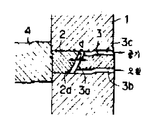
제 1 도는 본 발명에 의한 광분기 장치의 1실시예를 설명하기 위한 정면도.1 is a front view for explaining an embodiment of an optical branch device according to the present invention.
제 2 도는 제 1 도의 단면도.2 is a cross-sectional view of FIG.
제 3 도는 제 1 도의 Ⅲ-Ⅲ선 방향 에서 본 측면도.3 is a side view seen from the direction III-III of FIG.
제 4 도는 본 발명에 의한 광분기 장치의 다른 실시예를 설명하기 위한 정면도.4 is a front view for explaining another embodiment of the optical branch device according to the present invention.
제 5 도는 제 4 도의 단면도이다.5 is a cross-sectional view of FIG.
* 도면의 주요부분에 대한 부호의 설명* Explanation of symbols for main parts of the drawings
1 : 제 1 의 광도체롯드 1' : 클래드층1: 1st photoconductor rod 1 ': cladding layer
2 : 제 2 의 광도체롯드 2a : 경사면2: 2nd light conductor rod 2a: slope
3 : 제 3 의 광도체롯드 3a : 경사면3: 3rd light conductor rod 3a: sloped surface
3b, 3c : 홈 4 : 제 4 의 광도체롯드3b, 3c: Groove 4: Fourth light conductor rod
4' : 클래드층4 ': cladding layer
본 발명의 광도체내를 전송되어 오는 광에너지의 일부를 분기하여 그 광도체 외부로 빼내게한 광분기 장치에 관한 것이다.The present invention relates to an optical branching device which diverges a part of the optical energy transmitted through the optical conductor of the present invention and extracts it to the outside of the optical conductor.
본 출원인은 앞서, 태양광, 또는 인공광을 렌즈등에 의하여 접속하여서 광도체내에 도입하고, 이 광도체를 통하여 임의 소망의 장소에 전달하여 조명 기타의 사용에 제공하는 것에 대하여는 여러가지의 것을 제안하였다.The present applicant has previously proposed various things for introducing solar light or artificial light into a light conductor by connecting it with a lens or the like, and delivering the light to any desired place through the light conductor for use in lighting and the like.
그런데, 그때, 광도체내를 전송되어 오는 광에너지를, 그 전송 도중에 있어 상기 광도체로부터 분기하여 빼낼수 있다고 하면, 광에너지의 이용 효율을 더 한층 향상 시킬수가 있으나, 종래에는 이와같은 광분기 수단이 존재하지 아니하면서 대단히 불편하였다.By the way, if the optical energy transmitted in the optical conductor can be branched out of the optical conductor in the middle of the transmission, the utilization efficiency of the optical energy can be further improved. It didn't exist but was very uncomfortable.
본 발명은 상기에서와 같은 실정을 감안하여서 이루어진 것으로서, 특히 광도체롯드내를 전송되어 오는 광에너지의 일부를 이 광도체롯드로부터 분기하여 빼낼수 있도록 할 수 있는 광분기 장치를 제공하는 것을 목적으로 하는 것이다. 제 1 도는 본 발명에 의한 광분기 장치의 1실시예를 설명하기 위한 정면도, 제 2 도는 제 1 도의 단면도, 제 3 도는 제 1 도의 Ⅲ-Ⅲ선 방향에서 본 측면도로서, 도면중(1)은 제 1 의 광도체롯드이고, 이 광도체롯드(1)는 직경 방향으로 관통공이 뚫려져 있고, 이 관통공내에는 제 2 의 광도체롯드(2) 및 제 3 의 광도체롯드(3)가 끼워 넣어져 있으며, 광학풀 등으로 고정 설치되어 있다.The present invention has been made in view of the above circumstances, and an object of the present invention is to provide an optical branch device capable of branching out part of the optical energy transmitted from the optical conductor rod from the optical conductor rod. It is. FIG. 1 is a front view for explaining an embodiment of an optical branch device according to the present invention, FIG. 2 is a sectional view of FIG. 1, and FIG. 3 is a side view as seen from line III-III of FIG. Is the first photoconductor rod, and the
이 제 2 의 광도체롯드(2)는 삽입공내에 있어서의 끝단부가 제 1 의 광도체롯드(1)의 축 방향에 대하여 경사면(2a)으로 형성되고, 이 제 3 의 광도체롯드(3)는 상기의 제 2 의 광도체롯드(2)의 상기 경사면(2a)에 대향하는 경사면(3a)을 갖추고, 이들 경사면(2a 와 3a)은 소정의 간격(d)을 갖고 배열 설치되어 있다.The second
또한, 제 3 의 광도체롯드(3)는 제 3 도에 보이는 바와같이 제 1 의 광도체롯드(1)의 축선 방향의 대칭 위치에 이 제 3 의 광도체롯드(3)의 축방향에 따라 1쌍의 홈(3b, 3c)를 갖추고, 홈(3b)을 통하여 상기 제 2 도의 광도체롯드(2)와 제 3 도의 광도체롯드(3)의 간격내에 광학오일을 주입하며, 그 간격내의 공기를 홈(3c)을 통하여 배출하도록 하고 있다.In addition, the third
따라서, 제 1 의 광도체롯드(1)내를 화살표(A)방향으로 전송되어 있는 광(L)은 간격내에 광학오일이 들어 있지 않을때는 제 2 의 광도체롯드(2)의 경사면(2a)에 의하여 반사되어서 화살표(B) 방햐으로 진행하고, 간격내에 광학오일이 가득차 있을때는, 화살표(C) 방햐으로 진행하나, 그때, 화살표(B) 방향으로 진행하는 광의양은 간격내의 광학오일의 양에 의하여 조절할 수가 있고, 광학오일의 양이 적어질 수 화살표(B) 방향으로 진행하는 분기광량이 많아지게 된다. (4)는 광도체롯드(1)의 외주면에 상기 제 2 의 광도체롯드(2)의 넣어진 부분을 덮어서 고정시키거나 또는 상기 제 2 의 광도체롯드(2)와 일체적으로 형성된 제 4 의 광도체롯드로서, 상술한 바와같이하여 화살표(B) 방향으로 분기된 광은 제 4 의 광도체롯드(4)를 통하여 빼내어 지고, 이 제 4 의 광도체롯드(4)에 접속된 도시하지 않은 광도체케이블을 통하여 임의 소망의 장소에 전송되어, 조명 기타의 사용이 제공된다.Accordingly, the light L transmitted in the direction of the arrow A in the first
그리고(1') 및 (4')는 각각 제 1 의 광도체롯드(1) 및 제 4 의 광도체롯드(4)의 클래드층으로서, 도시한 실시예는 클래층이 피복되어 있는 광도체롯드에서 그 클래드츠을 삭제하여, 광분기 장치를 구성한 예를 나타낸 것이다.And (1 ') and (4') are cladding layers of the
처음부터 클래드층을 구비하고 있지 않은 광도체롯드를 사용하여도 좋은 것은 용이하게 이해할 수 있다.It is easily understood that an optical conductor rod which does not have a cladding layer from the beginning may be used.
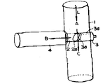
또한, 상기 본 발명에 의한 광분기 장치는 경사면(2a,3a)이 수평으로 되지 않도록 하는 위치로 사용하는 것도 용이하게 이해할 수 있다. 제 4 도는 본 발명에 광분기 장치의 다른 실시예를 설명하기 위한 정면도, 제 5 도는 단면도로서 도면중 제 1 도 내지 제 3 도와 동일한 작용을 하는 부분에서는 제 1 도 내지 제 3 도의 경우와 동동일한 참조번호를 부여하였다.In addition, it is also easily understood that the optical branch device according to the present invention can be used at a position such that the inclined surfaces 2a and 3a are not horizontal. FIG. 4 is a front view for explaining another embodiment of the optical branch device according to the present invention, and FIG. 5 is a sectional view in the same part as FIG. 1 to FIG. The same reference numerals are given.
그리고, 이 실시예에 있어서는, 제 3 의 광도체롯드(3)는 관통내에 진퇴 가능하게 끼워 넣어져 있고, 상단부에는 그 광도체롯드의 축방향에 따라 홈(d)이 설치되어 있어, 이 홈(3d)을 통하여 제 2 의 광도체롯드(2)의 경사면(2a)과 제 3의 광도체롯드(3)의 경사면(a)과의 사이의 간격(d)에 광학오일을 주입하고, 또한 제 3 의 광도체롯드(3)를 진퇴시키는때에, 이 공간의 공기를 배출하거나 또는 그 공간에 공기를 넣어, 이 제 3 의 광도체롯드의 진퇴를 용이하게 하고 있다.In this embodiment, the third
이와같이하여, 공간(d)내에 광학오일을 주입한 후에, 제 3 의 광도체롯드(3)를 밀어서 보내면, 공간(d)의 간격이 좁아져서 광학오일의 높이가 상승하고, 반대로, 뒤로 당기면 공간(d)의 간격이 넓어져서 광학오일의 높이가 저하한다.In this way, after the optical oil is injected into the space d, the third
그리고, 제 1 의 광도체롯드(1)내를 화살표(A) 방향으로 전송되어 있는 광(L)은 간격내의 광학오일이 들어 있지 않은 부분에서는 제 2 의광도체롯드(2)의 경사면(2a)에 의하여 반사되어 화살표(B) 방향으로 진행하는 광의 양은 간격내의 광학오일 높이에 의하여 조절할 수가 있고, 이 조절은 제 3 의 광도체롯드(3)의 끼워 넣는 깊이에 의하여 조정할 수가 있는 것이다.Then, the light L transmitted in the direction of the arrow A in the first
이상의 설명에서 명백한 바와같이, 본 발명에 의하면, 제작이 용이한 구성에 의하여 광학에너지를 효과적으로 분기할 수가 있고, 더욱 그 분기량을 조정할 수가 있는 광분기 장치를 제공할 수가 있는 것이다.As is apparent from the above description, the present invention can provide an optical branching device that can effectively branch optical energy and further adjust the amount of branching by a structure that is easy to manufacture.
Claims (4)
Applications Claiming Priority (5)
| Application Number | Priority Date | Filing Date | Title |
|---|---|---|---|
| JP58211643A JPS60103318A (en) | 1983-11-10 | 1983-11-10 | Optical branching device |
| JP???58-211643 | 1983-11-10 | ||
| JP211643 | 1983-11-10 | ||
| JP???58-215810 | 1983-11-16 | ||
| JP21581083A JPS60107605A (en) | 1983-11-16 | 1983-11-16 | Optical branching device |
Publications (2)
| Publication Number | Publication Date |
|---|---|
| KR850003795A KR850003795A (en) | 1985-06-26 |
| KR890003604B1 true KR890003604B1 (en) | 1989-09-27 |
Family
ID=16609173
Family Applications (1)
| Application Number | Title | Priority Date | Filing Date |
|---|---|---|---|
| KR1019890006965A KR890003604B1 (en) | 1983-11-10 | 1984-11-07 | Light diverting device |
Country Status (2)
| Country | Link |
|---|---|
| JP (1) | JPS60103318A (en) |
| KR (1) | KR890003604B1 (en) |
Families Citing this family (3)
| Publication number | Priority date | Publication date | Assignee | Title |
|---|---|---|---|---|
| JPS60107605A (en) * | 1983-11-16 | 1985-06-13 | Takashi Mori | Optical branching device |
| JPS60138510A (en) * | 1983-12-27 | 1985-07-23 | Takashi Mori | Optical branching device |
| DE4132071A1 (en) * | 1991-09-26 | 1993-04-08 | Kernforschungsz Karlsruhe | COUPLING ELEMENT FOR LIGHT GUIDE |
Family Cites Families (3)
| Publication number | Priority date | Publication date | Assignee | Title |
|---|---|---|---|---|
| US3937560A (en) * | 1974-11-29 | 1976-02-10 | The United States Of America As Represented By The Secretary Of The Navy | Single fiber access coupler |
| JPS5427445A (en) * | 1977-08-03 | 1979-03-01 | Fujitsu Ltd | Variable photo branching and coupling circuit |
| JPS566203A (en) * | 1979-06-28 | 1981-01-22 | Nippon Telegr & Teleph Corp <Ntt> | Photoswitch |
-
1983
- 1983-11-10 JP JP58211643A patent/JPS60103318A/en active Granted
-
1984
- 1984-11-07 KR KR1019890006965A patent/KR890003604B1/en not_active IP Right Cessation
Also Published As
| Publication number | Publication date |
|---|---|
| JPS6224764B2 (en) | 1987-05-29 |
| KR850003795A (en) | 1985-06-26 |
| JPS60103318A (en) | 1985-06-07 |
Similar Documents
| Publication | Publication Date | Title |
|---|---|---|
| US3995935A (en) | Optical coupler | |
| ES511409A0 (en) | IMPROVEMENTS IN THE MANUFACTURE OF CABLES WITH OPTICAL FIBERS. | |
| FR2431713A1 (en) | METHOD AND DEVICE FOR INTERCONNECTING FIBER OPTIC CABLES | |
| IT8223342A0 (en) | FIBER OPTIC CABLE IN SHEATH. | |
| KR890003112B1 (en) | Light diverting device | |
| JPS6428605A (en) | Optical fiber cable | |
| ATE13229T1 (en) | OPTICAL NEWS ELEMENT. | |
| KR890003604B1 (en) | Light diverting device | |
| ES510455A0 (en) | IMPROVEMENT IN THE MANUFACTURE PROCEDURE OF ELEMENTAL CABLES WITH OPTICAL FIBERS. | |
| NL194896B (en) | Fiber optic cable filler, optical fiber cable with an optical fiber surrounded by the filler and part of an optical fiber cable with an optical fiber in a tube filled with the filler. | |
| SE8305941D0 (en) | MFG LOW LOSS FIBER CABLE | |
| FR2312788A1 (en) | Fibre optics transmission cable - has sheath and plastics core with spiral slots in which fibres are placed | |
| DE3486016D1 (en) | OPTICAL NEWS CABLE. | |
| JPS57191603A (en) | Optical fiber unit for submarine cable | |
| US4636028A (en) | Light diverting device | |
| ES264177Y (en) | "AN IMPROVED FIBER OPTIC CABLE". | |
| EP0258839A3 (en) | Optical cable and method of making same | |
| KR890004151B1 (en) | Connecting structure for connecting optical conductor | |
| ES284364U (en) | Optical fiber joint with reinforcing filament and method of making such joint | |
| KR890003605B1 (en) | Optical diverting device | |
| GB2187304A (en) | Longitudinal sealing device for an optical cable core | |
| JPS57115504A (en) | Optical fiber cable and its manufacture | |
| BE901749A (en) | FIBER REINFORCED CONCRETE PIPE. | |
| JPS593411A (en) | Optical branching mechanism | |
| JPS60107605A (en) | Optical branching device |
Legal Events
| Date | Code | Title | Description |
|---|---|---|---|
| A201 | Request for examination | ||
| G160 | Decision to publish patent application | ||
| E701 | Decision to grant or registration of patent right | ||
| GRNT | Written decision to grant | ||
| FPAY | Annual fee payment |
Payment date: 19920828 Year of fee payment: 4 |
|
| LAPS | Lapse due to unpaid annual fee |