KR890003230B1 - Reversible fixed vane rotary compressor - Google Patents
Reversible fixed vane rotary compressor Download PDFInfo
- Publication number
- KR890003230B1 KR890003230B1 KR1019860004257A KR860004257A KR890003230B1 KR 890003230 B1 KR890003230 B1 KR 890003230B1 KR 1019860004257 A KR1019860004257 A KR 1019860004257A KR 860004257 A KR860004257 A KR 860004257A KR 890003230 B1 KR890003230 B1 KR 890003230B1
- Authority
- KR
- South Korea
- Prior art keywords
- chamber
- piston
- reversing
- fluid
- fluid communication
- Prior art date
Links
Images


Classifications
-
- F—MECHANICAL ENGINEERING; LIGHTING; HEATING; WEAPONS; BLASTING
- F04—POSITIVE - DISPLACEMENT MACHINES FOR LIQUIDS; PUMPS FOR LIQUIDS OR ELASTIC FLUIDS
- F04D—NON-POSITIVE-DISPLACEMENT PUMPS
- F04D27/00—Control, e.g. regulation, of pumps, pumping installations or pumping systems specially adapted for elastic fluids
-
- F—MECHANICAL ENGINEERING; LIGHTING; HEATING; WEAPONS; BLASTING
- F04—POSITIVE - DISPLACEMENT MACHINES FOR LIQUIDS; PUMPS FOR LIQUIDS OR ELASTIC FLUIDS
- F04C—ROTARY-PISTON, OR OSCILLATING-PISTON, POSITIVE-DISPLACEMENT MACHINES FOR LIQUIDS; ROTARY-PISTON, OR OSCILLATING-PISTON, POSITIVE-DISPLACEMENT PUMPS
- F04C28/00—Control of, monitoring of, or safety arrangements for, pumps or pumping installations specially adapted for elastic fluids
- F04C28/04—Control of, monitoring of, or safety arrangements for, pumps or pumping installations specially adapted for elastic fluids specially adapted for reversible pumps
-
- F—MECHANICAL ENGINEERING; LIGHTING; HEATING; WEAPONS; BLASTING
- F04—POSITIVE - DISPLACEMENT MACHINES FOR LIQUIDS; PUMPS FOR LIQUIDS OR ELASTIC FLUIDS
- F04C—ROTARY-PISTON, OR OSCILLATING-PISTON, POSITIVE-DISPLACEMENT MACHINES FOR LIQUIDS; ROTARY-PISTON, OR OSCILLATING-PISTON, POSITIVE-DISPLACEMENT PUMPS
- F04C18/00—Rotary-piston pumps specially adapted for elastic fluids
- F04C18/30—Rotary-piston pumps specially adapted for elastic fluids having the characteristics covered by two or more of groups F04C18/02, F04C18/08, F04C18/22, F04C18/24, F04C18/48, or having the characteristics covered by one of these groups together with some other type of movement between co-operating members
- F04C18/34—Rotary-piston pumps specially adapted for elastic fluids having the characteristics covered by two or more of groups F04C18/02, F04C18/08, F04C18/22, F04C18/24, F04C18/48, or having the characteristics covered by one of these groups together with some other type of movement between co-operating members having the movement defined in group F04C18/08 or F04C18/22 and relative reciprocation between the co-operating members
- F04C18/356—Rotary-piston pumps specially adapted for elastic fluids having the characteristics covered by two or more of groups F04C18/02, F04C18/08, F04C18/22, F04C18/24, F04C18/48, or having the characteristics covered by one of these groups together with some other type of movement between co-operating members having the movement defined in group F04C18/08 or F04C18/22 and relative reciprocation between the co-operating members with vanes reciprocating with respect to the outer member
- F04C18/3562—Rotary-piston pumps specially adapted for elastic fluids having the characteristics covered by two or more of groups F04C18/02, F04C18/08, F04C18/22, F04C18/24, F04C18/48, or having the characteristics covered by one of these groups together with some other type of movement between co-operating members having the movement defined in group F04C18/08 or F04C18/22 and relative reciprocation between the co-operating members with vanes reciprocating with respect to the outer member the inner and outer member being in contact along one line or continuous surfaces substantially parallel to the axis of rotation
- F04C18/3564—Rotary-piston pumps specially adapted for elastic fluids having the characteristics covered by two or more of groups F04C18/02, F04C18/08, F04C18/22, F04C18/24, F04C18/48, or having the characteristics covered by one of these groups together with some other type of movement between co-operating members having the movement defined in group F04C18/08 or F04C18/22 and relative reciprocation between the co-operating members with vanes reciprocating with respect to the outer member the inner and outer member being in contact along one line or continuous surfaces substantially parallel to the axis of rotation the surfaces of the inner and outer member, forming the working space, being surfaces of revolution
-
- F—MECHANICAL ENGINEERING; LIGHTING; HEATING; WEAPONS; BLASTING
- F04—POSITIVE - DISPLACEMENT MACHINES FOR LIQUIDS; PUMPS FOR LIQUIDS OR ELASTIC FLUIDS
- F04D—NON-POSITIVE-DISPLACEMENT PUMPS
- F04D29/00—Details, component parts, or accessories
- F04D29/08—Sealings
- F04D29/10—Shaft sealings
-
- F—MECHANICAL ENGINEERING; LIGHTING; HEATING; WEAPONS; BLASTING
- F25—REFRIGERATION OR COOLING; COMBINED HEATING AND REFRIGERATION SYSTEMS; HEAT PUMP SYSTEMS; MANUFACTURE OR STORAGE OF ICE; LIQUEFACTION SOLIDIFICATION OF GASES
- F25B—REFRIGERATION MACHINES, PLANTS OR SYSTEMS; COMBINED HEATING AND REFRIGERATION SYSTEMS; HEAT PUMP SYSTEMS
- F25B31/00—Compressor arrangements
- F25B31/02—Compressor arrangements of motor-compressor units
- F25B31/026—Compressor arrangements of motor-compressor units with compressor of rotary type
Landscapes
- Engineering & Computer Science (AREA)
- Mechanical Engineering (AREA)
- General Engineering & Computer Science (AREA)
- Physics & Mathematics (AREA)
- Thermal Sciences (AREA)
- Applications Or Details Of Rotary Compressors (AREA)
- Compressor (AREA)
Abstract
Description
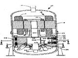
제1도는 제2도의 Ⅰ-Ⅰ선을 따른 수직 단면도.1 is a vertical cross-sectional view taken along the line I-I of FIG.
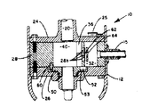
제2도는 제1도의 Ⅱ-Ⅱ선을 따른 단면도.2 is a cross-sectional view taken along the line II-II of FIG.
제3도는 제1도의 Ⅲ-Ⅲ선을 따른 단면도.3 is a cross-sectional view taken along the line III-III of FIG.
제4도는 제1도의 Ⅱ-Ⅱ선을 따른 베인의 단면도.4 is a cross-sectional view of the vane along line II-II of FIG.
제5도는 역전된 회전방향을 갖는 제2도 상응 도면.5 is a view corresponding to FIG. 2 with an inverted direction of rotation.
제6도는 역전딘 회전방향을 갖는 제3의 상응도면.FIG. 6 is a third corresponding figure with reversed rotation direction. FIG.
제7도는 제5도의 Ⅶ-Ⅶ선을 따른 부분 단면도.7 is a partial cross-sectional view taken along the line VII-VII of FIG. 5.
제8도는 역전 디스크와 베인의 구조물의 사시도.8 is a perspective view of the structure of the reversing disc and the vanes.
* 도면의 주요부분에 대한 부호의 설명* Explanation of symbols for main parts of the drawings
10 : 밀폐형 전동 압축기 유니트 12 : 셸(shell)10: hermetic electric compressor unit 12: shell
14, 15 : 라인 16 : 가역전동기14, 15: line 16: reversible motor
17 : 스테이터 18 : 로우터17: stator 18: rotor
20 : 크랭크축 21 : 편심바퀴20: crankshaft 21: eccentric wheel
22 : 압축기 28 : 크랭크 케이스22: compressor 28: crankcase
31, 32 : 플레넘 30 : 피스톤 챔버31, 32: Plenum 30: Piston Chamber
36 : 베인 40 : 로울링 피스톤36: vane 40: rolling piston
50 : 역전 디스크50: reversing disc
본 발명은 가역밀폐형 압축기 및 그 작동방법에 관한 것이다.The present invention relates to a reversible hermetic compressor and a method of operating the same.
열펌프에 있어서, 가열상태로부터 냉각상태로, 혹은 그 역으로 전환시키면, 증발기 및 응축기의 작용을 하는 코일의 기능이 뒤바뀌도록 냉매의 유동방향이 바뀌게 된다. 압축기가 단일 방향으로 작동하는 경우, 냉매의 유동방향의 변화는 일반적으로 압축기의 외부에 설치된 밸브를 통해서 이루어진다. 만약 압축기 자체가 역전 가능하면, 원하는 유동방향을 얻을 수 있도록 선택적으로 압축기를 운전할수는 있다. 전동기의 역전으로인한 압축기의 간단한 역전만으로는 양쪽 유동방향 모두에서 만족할만한 성능을 발휘하는 압축기를 제공하기는 어렵다. 이와같이 양쪽 방향에서 성능이 불균일한 것은 압축기의 고압축과 저압축 작동사이의 전환, 냉각요구조건 및 냉각유량과 유량체적의 변화, 출입구 기능의 역전, 개방 및 폐쇄방향의 역전등에 의해서 발생하는 것이다.In the heat pump, switching from a heated state to a cooled state or vice versa changes the flow direction of the refrigerant so that the functions of the coils acting as the evaporator and the condenser are reversed. When the compressor is operated in a single direction, the change in the flow direction of the refrigerant is generally made through a valve installed outside of the compressor. If the compressor itself is reversible, the compressor can optionally be operated to achieve the desired flow direction. It is difficult to provide a compressor that satisfies satisfactory performance in both flow directions only by simple inversion of the compressor due to the inversion of the motor. This uneven performance in both directions is caused by switching between high and low compression operation of the compressor, cooling requirements and changes in cooling flow rate and flow volume, reversal of the entrance function, and reversal in the opening and closing directions.
고정 베인 형식이나 로울링 피스톤 형식의 압축기에 있어서는, 원통형의 로울링 피스톤이 피스톤 챔버의 원통형 내벽과 서로 선형적인 로울링 접촉(rolling contact)을 하게 된다. 여기서 로울링 피스톤은 크랭크축에 설치된 편심바퀴에 의해서 움직이며, 피스톤 챔버이 벽과 로울링 접촉을 하여, 거의 360°에 걸친 초승달 모양의 챔버를 형성한다. 베인은 반경방향으로 이동이 가능하며, 로울링 피스톤과 접촉하여 상기 초승달 모양의 챔버를 흡입챔버와 방출챔버로 분리한다. 상기의 흡입챔버와 방출챔버는 로울링 피스톤과 피스톤 챔버의 벽사이의 선형 접촉의 위치에 따라 상대적인 순간 체적을 갖는다.In fixed vane type or rolling piston type compressors, the cylindrical rolling piston makes linear rolling contact with the cylindrical inner wall of the piston chamber. Here the rolling piston is moved by an eccentric wheel mounted on the crankshaft, and the piston chamber is in rolling contact with the wall, forming a crescent-shaped chamber spanning nearly 360 °. The vane is movable in the radial direction and in contact with the rolling piston separates the crescent-shaped chamber into a suction chamber and a discharge chamber. The suction chamber and the discharge chamber have a relative instantaneous volume depending on the position of the linear contact between the rolling piston and the wall of the piston chamber.
가역전동기에 의해 구동되는 고정 베인 형식 또는 로울링 피스톤 형식의 밀폐형 로타리 압축기에 있어서, 전동기의 방향이 역전되면 유출 입구제어구조가 변화된다. 특히, 역전 디스크에 형성된 흡입구는 디스크와 로울링 피스톤을 분리하는 유체 역학적 오일막을 통해서 이루어지는 점성마찰에 의하여 전동기의 회전 방향에 따른 두개의 위치 사이에서 이동하게 된다. 상기 두개의 상대적 위치 상태 각각에서, 흡입구는 제2플레넘이 압축 체적을 위한 방출 플레넘(plenum)이 될때, 플레넘과 실린더 흡입 체적 사이에서 흡입 기체의 통로를 형성한다. 전동기가 역전하게 되면 상기 두개의 플레넘은 그 기능이 역전된다. 방출 챔버의 압력은 역전디스크를 가압하여 이 역전 디스크가 크랭크 케이스와 금속과 금속간의 시일을 이루도록 하는데 사용된다.In the hermetic vane type or the rotary piston type sealed rotary compressor driven by the reversible motor, the outflow inlet control structure is changed when the direction of the motor is reversed. In particular, the suction port formed in the reversing disk is moved between two positions along the direction of rotation of the motor by viscous friction made through a hydrodynamic oil film separating the disk and the rolling piston. In each of the two relative position states, the inlet forms a passage of intake gas between the plenum and the cylinder intake volume when the second plenum becomes the outlet plenum for the compression volume. When the motor reverses, the two plenums reverse their function. The pressure in the discharge chamber is used to pressurize the reversing disc so that the reversing disc forms a seal between the crankcase and the metal.
본 발명의 먹적은 전동기의 회전방향이 역전될때, 가역고정베인 압축기가 양쪽 방향으로 효과적으로 유량을 전달할 수 있도록 하는 방법과 장치를 제공하는데있다.The present invention provides a method and apparatus for enabling a reversible fixed vane compressor to effectively transmit a flow rate in both directions when the rotation direction of the electric motor is reversed.
본 발명의 또 다른 목적은, 전동기의 회전방향을 역전시킴으로써 간단하게 역전되는 압축기를 제공하는데있다. 또 다른 목적은 실린더의 바닥면과 역전 디스크 사이의 간극을 줄이는데 있다.Another object of the present invention is to provide a compressor which is simply reversed by reversing the rotational direction of the electric motor. Another object is to reduce the gap between the bottom of the cylinder and the reversing disk.
본 발명의 또 다른 목적은, 모든 역전 구조물이 셸(shell)내에 구비되는 밀폐형 가역 압축기를 제공하는데있다.It is a further object of the present invention to provide a hermetic reversible compressor in which all of the reversing structures are provided in a shell.
본 발명의 또 따른 목적은 전동기의 회전방향에 반응하여 움직이는 단일흡입구를 제공하는데 있으며, 이상과 같은 본 발명의 목적 및 이하에서 좀더 상세히 설명될 목적은 본 발명에 의해 달성 되어진다.Another object of the present invention is to provide a single suction port that moves in response to the rotational direction of the motor, the object of the present invention as described above and the object to be described in more detail below is achieved by the present invention.
기본적으로, 고정 베인 형식 또는 로울링 피스톤 형식의 압축기를 구동하는 전동기의 회전방향이 역전되면 압축기의 작동이 역전되며, 이에 의해 유체의 유동 방향이 역전된다. 역전 디스크는 로울링 피스톤의 하부에 설치되며, 오일 시일을 통해서 이동하는 로울링 피스톤에 의해서 발생하는 점성 마찰력에 기인되어, 전동기의 회전방향에 따라 두개의 위치 사이에서 움직인다. 상기의 역전 디스크에는 그 위쪽의 실린더 벽의 반경 거리보다 더 큰 반경거리에 걸쳐 확장하여 흡입구로 작용하는 슬롯이 구비되어 있다. 디스크의 두가지 위치에서, 상기의 슬롯은 각각 베인의 서로 반대되는 위치에 설치되며, 베인의 양측에 위치된 각각의 플레넘과 유동 연결되어 있다. 베인이 로울링 피스톤의 편심운동에 의해 왕복운동하게 되면, 베인과 디스크는 서로 공동작용하여 방출챔버로부터 유체를 유동시킬 수 있는 유체 통로를 주기적으로 형성하고 디스크를 가압하여 크랭크 케이스와 시일링 작용을 하게 한다.Basically, when the rotation direction of the motor driving the compressor of the fixed vane type or the rolling piston type is reversed, the operation of the compressor is reversed, thereby reversing the flow direction of the fluid. The reversing disk is installed at the bottom of the rolling piston and is moved between two positions along the direction of rotation of the motor due to the viscous frictional force generated by the rolling piston moving through the oil seal. The reversing disc is provided with a slot which acts as an intake port and extends over a radial distance larger than the radial distance of the cylinder wall above it. In two positions of the disc, the slots are respectively installed at opposite positions of the vanes and are in fluid connection with the respective plenums located at both sides of the vanes. When the vanes are reciprocated by the eccentric motion of the rolling piston, the vanes and disks cooperate with each other to periodically form a fluid passage through which the fluid can flow from the discharge chamber, and pressurize the disk to seal the crankcase with the crankcase. Let's do it.
이하에서는 첨부도면을 참고하여 본원 발명을 좀더 상세하게 설명한다. 첨부하는 두면들은 셸(12)을 구비하는 밀폐형 전동 압축기 유니트(10)를 도시하고 있다. 셸(12)의 내부와 유체유동연결은 제1 및 제2라인(14, 15)를 통해서 각각 이루어진다. 상기 셸(12)내에는 스테이터(17)와 로우터(18)를 구비한 가역전동기(16)가 구비된다. 상기의 전동기(16)는 밀폐형 압축기에서 흔히 사용되는 공지 기술의 가역 전동기이다. 크랭크 축(20)에는 편심바퀴(21)가 포함되며, 공지된 바와같이 로우터(18)와 연결되어 함께 회전한다. 상기 크랭크 축(20) 이외에도 압축기(22)에는 상부 베어링 캡(24)와 하부 베어링 캡(26)이 구비되고, 이들 베어링 캡(24, 26) 사이에는 크랭크 케이스(28)가 설치되어 있다.Hereinafter, the present invention will be described in more detail with reference to the accompanying drawings. The accompanying two sides show a hermetic
제2도에서 정확하게 나타내고 있는 것처럼, 크랭크 케이스(28)에는 원통형의 피스톤 챔버(20)와 플레넘(31, 32)이 형성되고, 또한 반경방향으로 연장한 베인 슬롯(vane slot)(34)과 챔버(35)도 마련된다. 베인(36)은 상기 베인 슬롯(34)과 챔버(35)내에 왕복운동이 가능하도록 설치되며, 상기 베인(36)을 가로질러 발생하는 유체의 누출을 막기 위해 베인 슬롯(34)의 벽에 대해 밀착 접촉을 하고 있다. 로울링 피스톤(40)은 편심바퀴(21)에 의해 구동되어 피스톤 챔버(30)의 원주를 따라서 로울링 접촉을 한다. 베인(36)은 스프링(38, 39)에 의해 가압되어 로울링 피스톤(40)과 접촉하고 있다. 역전 디스크(50)는 로울링 피스톤(40)과 크랭크 케이스(28)의 일부의 아래에 위치하며, 하부 베어링 캡(26)내의 대응 홈내에 수용되어 있다. 상기 역전 디스크(50)의 상부면에는 한쌍의 원호상 슬롯(51, 52)이 형성되어 있으며, 이들 슬롯(51, 52)은 각각 회전 제한 구조물 및 흡입구로써 작용한다. 역전 디스크(50)의 하부면에는 원주홈(53)이 형성되어 있으며, 이 홈(53)은 원주 방향을 따라 이격 형성된 통로(54, 55)를 통해서 상부면과 유체 연통된다. 역전 디스크(50)의 하부에는 환형의 홈(56)이 형성되어 있으며, 이 환형홈(56)내에는 0-링(58)이 수용되어 있다. 또한 상기 크랭크 케이스(28)내에는 하나의 핀(60)이 고정적으로 수용되어 원호상 슬롯(51)속으로 연장하고 있다.As shown in FIG. 2, the
플레넘(31, 32)은 각각 방출 밸브(61, 62)를 포함하며, 이들 밸브(61, 62)에는 밸브 스톱(63, 64)이 구비되어있다. 상기 밸브(61, 62) 및 밸브 스톱(63, 64)은 다수의 통로(28a, 28b)를 제어할 수 있는 형태를 갖는다. 도시된 바와같이, 통로(28a, 28b)는 각각 3개의 개구로 이루어지며, 각각 E자 형태를 갖는 밸브(61, 62) 및 밸브스톱(63, 64)에 의해 3개의 개구는 모두 덮어지게 된다. 라인(15)은 플레넘(32)과 직접적으로 연결되어 있고, 라인(14)은 상부 베어링 캡(24)를 통해 연장하고 있는 통로(25)와 셸(12)의 내부를 통해서 플레넘(31)과 유체 연통되어 있다. 제4도에서 상세히 도시되어 있는 것처럼, 베인(36)의 양측면에는 반경방향으로 연장된 홈(36a, 36b)이 구비되어 있으며, 이들 홈(36a, 36b)은 축방향으로 연장된 대응 홈(37a, 37b)와 가각 유체 연통된다. 크랭크축(20)의 하단부에는 공지의 기술과 같이 오일피컵(pick up) 튜브(66)가 위치하고, 오일 갤리(galley)(68)는 크랭크축(20)의 축방향으로 연장되며, 오일공급 개구(68a)가 마련된다.The
작동에 있어서는, 로울링 피스톤(40)과 베인(36)의 상호 작용은 마치 캠과 캠종동자의 상호작용과 유사하게 이루어진다. 즉, 로울링 피스톤(40)이 피스톤 챔버(30)의 벽을 따라서 구르는 동안 로울링 피스톤(40)의 회전이 편심바퀴(21)에 의해 베인(36)을 왕복운동시키게 된다. 제1도부터 제3도까지를 참고하면, 여기에 도시되는 밀폐형 압축기 유니트(10)는 흡입 라인으로 작용하는 제1라인(14)와 방출 라인으로 작용하는 제2라인(15)를 구비하는 저압측의 압축기로 작용하고 있다. 크랭크축(20)과 편심바퀴(21)는 제2도의 화살표 방향과 같이 반시계 방향으로 회전한다. 냉매는 제2라인(14)을 통해서 셸(12)내로 들어가서 전동기(16) 구조물을 앤각시킨 다음에 통로(25)를 통해 흡입 플레넘의 작용하는 플레넘(31)내로 유입된다. 이 흡입플레넘(31)으로부터 나온 냉매는 역전 디스크(50)에 형성된 슬롯(52)을 통하여 피스톤 챔버(30)의 부위(30a)속으로 들어간다. 상기 피스톤 챔버(30)의 부위(30a)가 흡입 플레넘(31)과 서로 유체 연통 상태를 유지하는 동안, 상기 부위(30a)는 흡입 챔버로써 작용한다. 일단 흡입 플레넘(31)과의 유체 연통 상태가 단절되어 버리면, 피스톤 챔버(30)의 부위(30b)이 경우에서 처럼 갇혀진(trapped) 체적은 방출 챔버가 된다. 방출 챔버(30b)는 통상 폐쇄되어 있는 방출 밸브(62)의 제어하에서 통로(28b)를 통하여 방출 플레넘(32)과 유체 연통된다. 방출플레넘(32)속으로 들어간 냉매는 제1라인(15)를 통해서 압축기로부터 배출된다. 회전시, 로울링 피스톤(40)과 역전 디스크(50) 사이에 발생하는 오일 시일(oil seal)의 점성 마찰에 의해 디시크(50)은 연속적으로 운동하게 되며, 핀(60)은 슬롯(51)과 협동하여 디스크(50)의 운동을 슬롯의 크기내에서 제한한다. 회전방향이 역전되면, 디스크(50)와 크랭크 케이스(28) 사이의 금속대 금속 시일을 유발하는 유체 압력은 디스크를 다른 한계 위치로 이동시키는데 충분한 점성 마찰이 형성되기 전에 해제시켜야 한다.In operation, the interaction of the rolling
상술한 바와같이, 베인(36)은 편심바퀴(21)의 회전 및 이 회전에 따른 로울링 피스톤(40)의 회전에 의해 왕복운동을 하게 된다. 제1도 및 제2도를 참조하면, 베인(36)이 도시된 위치에서 외측 방향으로 이동하면 방출 챔버(30b)와 원주홈(53)사이에 홈(36a, 37b)과 통로(55)를 통한 유체 연통 상태가 형성된다. 챔버(30a)가 방출 챔버로 작용하는 경우에는 상기 챔버(30a)는 홈(36a, 37a) 및 통로(54)에 의해 이루어지는 대응 유체 통로를 통해서 동일한 유체 연통 상태가 된다. 이러한 유체 연통이 형성된 경우, 방출 행정(stroke)의 정확한 모우멘트는 압축기의 고유한 설계에 의해서 결정되어 지지만, 기본적으로는 상기 모우멘트는 홈(53)을 주기적으로 방출 압력 상태에 위치시켜서 크랭크 케이스(28)에 대한 역전 디스크(50)의 시일링 가압(SEALING BIAS)를 달성한다. O-링(58)은 홈(37b)과 통로(55) 사이에서의 유체 연통을 차단함으로써 홈(53)으로부터의 누출을 방지한다.As described above, the
만약 전동기(16)가 역전되어 크랭크축(20)과 편심바퀴(21)이 제5도의 화살표 방향인 시계방향으로 회전하게 되면 편심바퀴(21)에 위해 구동되는 로울링 피스톤(40)의 회전에 의해 디스크(50)은 점성 마찰에 기인되어 제2도 및 제3도에 도시된 위치로부터 제5도 및 제6도에 도시된 위치로 시계방향으로 회전하려 하지만 상기 디스크(50)와 크랭크 케이스(28) 사이의 금속대 금속간의 접촉관계가 초기에 이러한 회전을 방지하므로 디스크(50)은 제2도와 제3도에 도시된 위치에 그냥 머물러 있게 된다. 챔버(30b)는 전동기의 회전방향이 시계방향으로 역전될때 흡입챔버가 된다. 그러나 디스크(50)가 제5도와 제6도에 도시된 위치에 오기전에는 슬롯(52)는 흡입구로써 작동할 수 있는 적절한 위치에 있지 못하며, 따라서 이때까지는 챔버(30b)가 진공상태에 있게 된다. 베인(36)의 왕복운동은 주기적으로 계속되어 홈(36b, 37b) 및 통로(55)에 의해 형성되는 유체통로를 형성한다. 그러나 압력의 차이에 의해 홈(53)으로부터 챔버(30b)쪽으로 가압된 유체가누출된다. 홈(53)내의 유체 압력이 디스크(50)와 크랭크 케이스(28) 사이의 금속대 금속간의 시일을 해제할 수 있을 정도로 충분히 떨어지면, 로울링 피스톤(40)과 디스크(50) 사이의 점성 마찰 즉, 토오크는 로울링 피스톤(40)의 이동방향으로 슬롯(51)의 단부에 접촉한 핀(60)에 의해서 제한되는 위치인 제5도와 제6도의 위치로 디스크(50)를 전환시키기에 충분해진다. 제5도와 제6도의 위치는 슬롯(52)가 흡입구로써 작동하기에 적절한 위치이며, 챔버(30b)가 제공된다. 제5도와 제6도의 위치에서, 베인(36)의 왕복운동에 의해 방출 챔버와 홈(53)사이에 홈(36a, 37a)과 통로(54)를 통한 유체 연통이 형성되고, 이에 의해 크랭크 케이스(28)와 디스크(50) 사이에 전술한 바와 같은 금속대 금속간의 시일 작용이 이루어진다.If the
제5도에서 제7도까지는 제1라인(15)가 흡인 라인으로 작용하고, 제2라인(14)가 방출 라인으로 작용하는 고압측 압축기로서 동작하는 밀폐형 압축기 유니트(10)를 도시한 것이다. 여기서 냉매는 라인(15)를 통해 흡입 플레넘으로 작용하는 플레넘(32)속으로 들어간다. 피스톤 챔버(30)로부터 방출 플레넘으로 작용하는 플레넘(31)으로 방출된 냉매는 통로(25)를 통해서 셸(12)의 내부로 들어간다. 여기서 냉매는 전동기(16)의 구조물을 경유한 다음, 제2라인(14)을 통해 압축기 유니트(10)로부터 배출된다. 제7도에 더욱 상세히 도시되어 있는 것처럼, 슬롯(52)은 흡입 플레넘(32)와 피스톤 챔버(30b) 사이에 자유 유체 연통을 제공하며, 상기 챔버(30b)는 흡입 챔버로 작용하고 흡입 플레넘(32)와 유체 연통 상태에 있는 한은 계속 흡입 챔버로 작용하게 된다. 일단 흡입 플레넘(32)과의 유체 연통 상태가 차단되면, 피스톤 챔버(30)의 부위(30a)의 경우와 같은 갇힌(trapped) 체적은 방출 챔버가 된다. 상기 방출 챔버(30a)는 통상적으로 폐쇄되어 있는 방출 밸브(61)의 제어에서 통로(28a)를 통해서 방출 플래넘(31)과 유체 연통되어 있다.5 to 7 show a
전술한 바와같은 저압축 작동의 경우와 마찬가지로 베인(36)의 이동에 의해 홈(36a, 37a) 및 통로(54)를 통해서 방출 챔버(30a)와 원주홈(53)사이에 유체 연통이 주기적으로 형성된다. 챔버(30b)는 방출 챔버로 작용하는 경우에 동일한 유체 연통 상태에 있게 된다. 전술한 바와같이 홈(53)내에서 작용하는 방출 압력에 의해 역전 디스크(50)은 크랭크 케이스(28)에 대해 시일링 가압(sealing bias)되는데, 이 시일링 가압은 전술한 바와 같이 전동기 회전방향의 역전에 의해서 감소되거나 소멸되어 로울링 피스톤(40)에 의한 디스크(50)의 운동을 허용할수 있게 된다.As in the case of the low compression operation as described above, fluid communication periodically occurs between the discharge chamber 30a and the
이상의 설명으로부터 알 수 있는 바와같이, 양쪽의 작동방향에 대해 동일한 유입구 구조가 사용될 수 있으므로 흡입 라인과 방출 라인에서 체적 유량에 차이가 발생되는 문제를 피할수 있다. 또한 양쪽의 작동방향 각각에 방출 밸브를 사용할 수 있다. 입구 구조물의 재위치 설정은 전동기에 의해서 직접 구동되는 로울링 피스톤에 의해서 생성되는 점성 마찰력에 의해 이루어진다. 따라서 전동기의 회전방향을 역전시킴으로써 역전되는 초기의 압축기 구조가 된다.As can be seen from the above description, the same inlet structure can be used for both operating directions, thereby avoiding the problem of a difference in the volume flow rate in the suction line and the discharge line. It is also possible to use discharge valves in each of the two operating directions. Repositioning of the inlet structure is made by viscous frictional forces generated by a rolling piston driven directly by the electric motor. Therefore, the initial compressor structure is reversed by reversing the rotational direction of the electric motor.
비록 이상에서 본 발명의 바람직한 실시예를 들어 도시하고 설명하였지만 본 발명은 첨부한 특허 청구범위에서 벗어나지 않는 한도내에서 여러가지 변형예도 있을 수 있다.Although illustrated and described with reference to the preferred embodiment of the present invention, the present invention may be modified in various ways without departing from the appended claims.
Claims (4)
Applications Claiming Priority (2)
| Application Number | Priority Date | Filing Date | Title |
|---|---|---|---|
| US739,786 | 1985-05-31 | ||
| US06/739,786 US4598559A (en) | 1985-05-31 | 1985-05-31 | Reversible fixed vane rotary compressor having a reversing disk which carries the suction port |
Publications (2)
| Publication Number | Publication Date |
|---|---|
| KR860009240A KR860009240A (en) | 1986-12-20 |
| KR890003230B1 true KR890003230B1 (en) | 1989-08-27 |
Family
ID=24973771
Family Applications (1)
| Application Number | Title | Priority Date | Filing Date |
|---|---|---|---|
| KR1019860004257A KR890003230B1 (en) | 1985-05-31 | 1986-05-30 | Reversible fixed vane rotary compressor |
Country Status (7)
| Country | Link |
|---|---|
| US (1) | US4598559A (en) |
| JP (1) | JPH0742955B2 (en) |
| KR (1) | KR890003230B1 (en) |
| BR (1) | BR8602358A (en) |
| DK (1) | DK254086A (en) |
| FR (1) | FR2582744A1 (en) |
| IT (1) | IT1190022B (en) |
Cited By (1)
| Publication number | Priority date | Publication date | Assignee | Title |
|---|---|---|---|---|
| KR101154946B1 (en) * | 2004-10-12 | 2012-06-14 | 엘지전자 주식회사 | Air-conditioner |
Families Citing this family (22)
| Publication number | Priority date | Publication date | Assignee | Title |
|---|---|---|---|---|
| JPH01240785A (en) * | 1988-03-22 | 1989-09-26 | Atsugi Motor Parts Co Ltd | Vane type rotary compressor |
| HU217275B (en) * | 1994-02-24 | 1999-12-28 | Rába Rt. | Reverser closing slide-valve pump mainly for circulating of lubricant of driving devices |
| CN100386575C (en) * | 1998-07-02 | 2008-05-07 | 株式会社鹭宫制作所 | Flow path selector valve and method of selecting and driving valve compressor with flow path selector valve, and refrigerating cycle control device |
| JP2001050184A (en) * | 1999-08-05 | 2001-02-23 | Sanyo Electric Co Ltd | Multiple cylinder rotary compressor |
| WO2004053335A1 (en) * | 2002-12-11 | 2004-06-24 | Matsushita Electric Industrial Co., Ltd. | Rotary compressor |
| KR100531284B1 (en) * | 2003-05-13 | 2005-11-28 | 엘지전자 주식회사 | Rotary compressor |
| KR100531287B1 (en) * | 2003-05-13 | 2005-11-28 | 엘지전자 주식회사 | Rotary compressor |
| KR100531285B1 (en) | 2003-05-13 | 2005-11-28 | 엘지전자 주식회사 | Rotary compressor |
| KR100531281B1 (en) * | 2003-05-13 | 2005-11-28 | 엘지전자 주식회사 | rotary compressor |
| KR100531288B1 (en) * | 2003-05-13 | 2005-11-28 | 엘지전자 주식회사 | Rotary compressor |
| KR100519341B1 (en) * | 2003-05-13 | 2005-10-07 | 엘지전자 주식회사 | Rotary compressor |
| KR100525412B1 (en) * | 2003-05-13 | 2005-11-02 | 엘지전자 주식회사 | System for controlling compressor of cooling system and method for controlling compressor |
| KR100519312B1 (en) * | 2003-06-11 | 2005-10-07 | 엘지전자 주식회사 | Rotary compressor |
| KR100519311B1 (en) * | 2003-06-11 | 2005-10-07 | 엘지전자 주식회사 | Rotary compressor |
| JP4331725B2 (en) * | 2003-10-29 | 2009-09-16 | エルジー エレクトロニクス インコーポレイティド | Operation control method and apparatus for compressor of refrigerator |
| WO2006046784A1 (en) | 2004-10-26 | 2006-05-04 | Lg Electronics Inc. | Rotary compressor |
| US7491037B2 (en) * | 2005-08-05 | 2009-02-17 | Edwards Thomas C | Reversible valving system for use in pumps and compressing devices |
| KR100835187B1 (en) | 2007-03-20 | 2008-06-04 | 엘지전자 주식회사 | Rotary compressor |
| EP2612035A2 (en) | 2010-08-30 | 2013-07-10 | Oscomp Systems Inc. | Compressor with liquid injection cooling |
| US9267504B2 (en) | 2010-08-30 | 2016-02-23 | Hicor Technologies, Inc. | Compressor with liquid injection cooling |
| KR101727801B1 (en) * | 2015-05-22 | 2017-04-17 | 엘지전자 주식회사 | A rotary compressor and a method manufacturing the same |
| WO2017080599A1 (en) * | 2015-11-12 | 2017-05-18 | Pierburg Pump Technology Gmbh | Electric motor vehicle vacuum pump |
Family Cites Families (8)
| Publication number | Priority date | Publication date | Assignee | Title |
|---|---|---|---|---|
| US2844945A (en) * | 1951-09-19 | 1958-07-29 | Muffly Glenn | Reversible refrigerating systems |
| US3723024A (en) * | 1969-12-30 | 1973-03-27 | Daikin Ind Ltd | Reversible rotary compressor for refrigerators |
| JPS5125226Y2 (en) * | 1972-05-08 | 1976-06-28 | ||
| JPS50118308A (en) * | 1974-03-02 | 1975-09-17 | ||
| US3985473A (en) * | 1975-07-10 | 1976-10-12 | Copeland Corporation | Rotary pump |
| JPS5421610A (en) * | 1977-07-20 | 1979-02-19 | Hitachi Ltd | Mermetic rerigerant compressor |
| US4367638A (en) * | 1980-06-30 | 1983-01-11 | General Electric Company | Reversible compressor heat pump |
| US4445344A (en) * | 1982-09-07 | 1984-05-01 | General Electric Company | Reversible refrigeration system rotary compressor |
-
1985
- 1985-05-31 US US06/739,786 patent/US4598559A/en not_active Expired - Fee Related
-
1986
- 1986-05-22 BR BR8602358A patent/BR8602358A/en not_active IP Right Cessation
- 1986-05-29 IT IT20615/86A patent/IT1190022B/en active
- 1986-05-30 FR FR8607834A patent/FR2582744A1/en active Granted
- 1986-05-30 DK DK254086A patent/DK254086A/en not_active Application Discontinuation
- 1986-05-30 JP JP61125547A patent/JPH0742955B2/en not_active Expired - Fee Related
- 1986-05-30 KR KR1019860004257A patent/KR890003230B1/en not_active IP Right Cessation
Cited By (1)
| Publication number | Priority date | Publication date | Assignee | Title |
|---|---|---|---|---|
| KR101154946B1 (en) * | 2004-10-12 | 2012-06-14 | 엘지전자 주식회사 | Air-conditioner |
Also Published As
| Publication number | Publication date |
|---|---|
| JPS61277892A (en) | 1986-12-08 |
| BR8602358A (en) | 1987-01-21 |
| IT8620615A0 (en) | 1986-05-29 |
| US4598559A (en) | 1986-07-08 |
| JPH0742955B2 (en) | 1995-05-15 |
| DK254086D0 (en) | 1986-05-30 |
| KR860009240A (en) | 1986-12-20 |
| IT1190022B (en) | 1988-02-10 |
| IT8620615A1 (en) | 1987-11-29 |
| FR2582744A1 (en) | 1986-12-05 |
| FR2582744B1 (en) | 1993-02-26 |
| DK254086A (en) | 1986-12-01 |
Similar Documents
| Publication | Publication Date | Title |
|---|---|---|
| KR890003230B1 (en) | Reversible fixed vane rotary compressor | |
| US4854825A (en) | Multi-stage vacuum pump | |
| US5482443A (en) | Multistage vacuum pump | |
| US5383773A (en) | Orbiting rotary compressor having axial and radial compliance | |
| US2712794A (en) | Fluid motor or pump | |
| US3852003A (en) | Pressure-sealed compressor | |
| US3175510A (en) | Variable displacement pump | |
| US5472327A (en) | Rotary compressor with improved fluid inlet porting | |
| GB2044357A (en) | Rotary positive-displacement fluid-machines | |
| US6217303B1 (en) | Displacement fluid machine | |
| US3985473A (en) | Rotary pump | |
| US5284426A (en) | Rotary compressor with multiple compressor stages and pumping capacity control | |
| US5015161A (en) | Multiple stage orbiting ring rotary compressor | |
| JPH0419395B2 (en) | ||
| US4447196A (en) | Rotary vane compressor with valve control of undervane pressure | |
| US4219314A (en) | Rolling piston rotary compressor | |
| GB1566687A (en) | Pump | |
| US4484863A (en) | Rotary vane pump with undervane pumping and an auxiliary outlet | |
| US4003682A (en) | Rotary piston engine having continuous torque characteristics | |
| US5979501A (en) | Fluid distributing apparatus for piston-type hydraulic motors or pumps | |
| US4480965A (en) | Capacity modulation device for compressor | |
| US3844685A (en) | Vane machine with pressure bias and balancing means for the rotary control port member | |
| US4813858A (en) | Gerotor pump with pressure valve and suction opening for each pressure chamber | |
| US4265165A (en) | Radial piston fluid translating device with power conserving scavenging means | |
| US3554676A (en) | Vapor compressor |
Legal Events
| Date | Code | Title | Description |
|---|---|---|---|
| A201 | Request for examination | ||
| E902 | Notification of reason for refusal | ||
| G160 | Decision to publish patent application | ||
| E701 | Decision to grant or registration of patent right | ||
| GRNT | Written decision to grant | ||
| FPAY | Annual fee payment |
Payment date: 20050708 Year of fee payment: 17 |
|
| EXPY | Expiration of term |