KR890000552B1 - Device for accommodating bending of a cable - Google Patents
Device for accommodating bending of a cable Download PDFInfo
- Publication number
- KR890000552B1 KR890000552B1 KR1019830006154A KR830006154A KR890000552B1 KR 890000552 B1 KR890000552 B1 KR 890000552B1 KR 1019830006154 A KR1019830006154 A KR 1019830006154A KR 830006154 A KR830006154 A KR 830006154A KR 890000552 B1 KR890000552 B1 KR 890000552B1
- Authority
- KR
- South Korea
- Prior art keywords
- connecting shaft
- cylinder
- holder
- main connecting
- piston rod
- Prior art date
- Legal status (The legal status is an assumption and is not a legal conclusion. Google has not performed a legal analysis and makes no representation as to the accuracy of the status listed.)
- Expired
Links
Images


Classifications
-
- A—HUMAN NECESSITIES
- A61—MEDICAL OR VETERINARY SCIENCE; HYGIENE
- A61B—DIAGNOSIS; SURGERY; IDENTIFICATION
- A61B1/00—Instruments for performing medical examinations of the interior of cavities or tubes of the body by visual or photographical inspection, e.g. endoscopes; Illuminating arrangements therefor
- A61B1/005—Flexible endoscopes
- A61B1/0051—Flexible endoscopes with controlled bending of insertion part
- A61B1/0055—Constructional details of insertion parts, e.g. vertebral elements
-
- B—PERFORMING OPERATIONS; TRANSPORTING
- B25—HAND TOOLS; PORTABLE POWER-DRIVEN TOOLS; MANIPULATORS
- B25J—MANIPULATORS; CHAMBERS PROVIDED WITH MANIPULATION DEVICES
- B25J9/00—Program-controlled manipulators
- B25J9/06—Program-controlled manipulators characterised by multi-articulated arms
-
- G—PHYSICS
- G02—OPTICS
- G02B—OPTICAL ELEMENTS, SYSTEMS OR APPARATUS
- G02B23/00—Telescopes, e.g. binoculars; Periscopes; Instruments for viewing the inside of hollow bodies; Viewfinders; Optical aiming or sighting devices
Landscapes
- Health & Medical Sciences (AREA)
- Life Sciences & Earth Sciences (AREA)
- Physics & Mathematics (AREA)
- Engineering & Computer Science (AREA)
- Surgery (AREA)
- Optics & Photonics (AREA)
- Animal Behavior & Ethology (AREA)
- Veterinary Medicine (AREA)
- Pathology (AREA)
- Nuclear Medicine, Radiotherapy & Molecular Imaging (AREA)
- Biomedical Technology (AREA)
- Heart & Thoracic Surgery (AREA)
- Medical Informatics (AREA)
- Molecular Biology (AREA)
- Biophysics (AREA)
- General Health & Medical Sciences (AREA)
- Public Health (AREA)
- Radiology & Medical Imaging (AREA)
- Robotics (AREA)
- Mechanical Engineering (AREA)
- Astronomy & Astrophysics (AREA)
- General Physics & Mathematics (AREA)
- Instruments For Viewing The Inside Of Hollow Bodies (AREA)
- Endoscopes (AREA)
- Investigating Strength Of Materials By Application Of Mechanical Stress (AREA)
- Actuator (AREA)
- Rigid Pipes And Flexible Pipes (AREA)
- Mechanical Control Devices (AREA)
Abstract
내용 없음.No content.
Description
제1도는 종래의 굴곡장치의 일부 생략사시도.1 is a partially omitted perspective view of a conventional bending device.
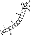
제2도는 본 발명의 굴곡장치를 이용한 파이버스코오프의 사시도.2 is a perspective view of a fiberscooff using the bending device of the present invention.
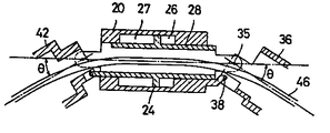
제3도는 본 발명의 굴곡장치 단면도3 is a cross-sectional view of the bending device of the present invention
제4도는 제3도의 Ⅳ-Ⅳ선의 단면도.4 is a cross-sectional view taken along the line IV-IV of FIG.
제5도 및 제6도는 작용설명을 위한 개략단면도.5 and 6 are schematic cross-sectional views for explaining the operation.
* 도면의 주요부분에 대한 부호의 설명* Explanation of symbols for main parts of the drawings
20 : 실린더 24 : 피스톤20: cylinder 24: piston
26 : 제1압력실 27 : 제2압력실26: first pressure chamber 27: second pressure chamber
28 : 피스톤로드 34 : 돌출부28: piston rod 34: protrusion
35 : 제1주연결축 36 : 제1호울더35: primary connecting shaft 36: the first holder
37 : 돌출부 38 : 제1보조연결축37: protrusion 38: first auxiliary connecting shaft
39 : 긴구멍 40 : 돌출부39: long hole 40: protrusion
41 : 제2주연결축 42 : 제2호울더41: 2nd main connecting shaft 42: 2nd holder
43 : 돌출부 44 : 제2보조연결축43: projection 44: second auxiliary connecting shaft
45 : 긴구멍45: long hole
본 발명은, 전기케이블, 광파이버케이블, 와이어 등의 장척물을 삽통 또는 연결한 기기 일반에 사용되며, 기기의 일부를 원격조작에 의해서 굴곡시키기 위하여 사용되는 굴곡장치에 관한 것이다.BACKGROUND OF THE INVENTION 1. Field of the Invention [0001] The present invention relates to a bending device used in general for a device that inserts or connects a long object such as an electric cable, an optical fiber cable, a wire, and the like to bend a part of the device by a remote operation.
종래 파이버스코오프의 촬상부에 굴곡장치를 개재하여, 그 굴곡장치를 수상부에서의 조작으로 작동해서 촬상부의 방향을 바꾸는 것은, 예를 들면 위 카메라 등에서 잘 볼수 있는 구조이다. 제1도는 그 구체적인 구조이며, 촬상부(1)에 소요수의 마디고리(2)를 핀(3)으로 굴곡자재하게 연결함과 동시에, 촬상부(1)에 고정한 2본의 와이어(4)를 상기 핀(3)으로부터 90도 떨어진 위치에서 각 마디고리(2)에 삽통하고, 그 타단을 수상부에 착설된 풀리(5)에 감아서, 그 풀리(5)를 핸들(6)로 회전하므로서, 촬상부(1)의 방향을 바꾸도록 한 것이다.It is a structure which can be easily seen with the above camera etc., for example, to operate the bending apparatus by the operation | movement in a water phase part, and to change the direction of an imaging part via the bending apparatus in the imaging part of the conventional fibersco-off. FIG. 1 is a concrete structure thereof. The two wires 4 which are flexibly connected to the imaging unit 1 with the required number of rings 2 with the
상기의 같은 마디고리(2)를 이용한 종래의 굴곡장치는, 와이어(4) 자체의 늘어짐이나 마찰 등으로 굴곡각도를 크게할 수가 없으며, 특히 조작부로부터의 거리가 멀어지면 와이어(4)의 움직임이 선단까지 전달되기가 어렵고, 그 때문에 굴곡각도가 작아지는 문제가 있다.In the conventional bending device using the above-described knot 2, the bending angle cannot be increased due to the sagging or friction of the wire 4 itself, and in particular, when the distance from the operation unit increases, the movement of the wire 4 becomes difficult. It is difficult to be delivered to the tip, and therefore there is a problem that the bending angle is reduced.
본 발명은, 상기한 바와 같은 문제점을 해결한 원격조작에 의해서 작동되는 굴곡장치를 제공하는 것을 목적으로 하고 있다. 그 목적을 달성하기 위해서, 본 발명은 북동식 유채압실린더의 피스톤로드 일단에 제1주연결축에 의해서 제1호울더를 회동자재하게 연결하고, 그 제1주연결축에 대한 피스톤로드의 힘의 작용선에서 소요의 간격을 둔 위치에서 실린더의 일단과 상기 제1호울더를 제1주연결축과 평행인 제1보조연결축에 의해서 소요의 여유가 있게 회동 자재하게 연결하고, 상기 실린더의 타단에 제2주 연결축에 의해서 제2호울더를 회동 자재하게 연결하며, 그 제2주 연결축에 대한 실린더의 힘의 작용선에서 소요의 간격을 둔 위치에서 상기 피스톤로드의 타단과 상기 제2호울더를 제2주 연결축과 평행인 제2보조 연결축에 의해서 소용의 여유를 가지고 회동 자재하게 연결한 구성으로 한 것이다.An object of the present invention is to provide a bending device that is operated by a remote operation that solves the above problems. In order to achieve the above object, the present invention pivotally connects the first holder to the one end of the piston rod of the northeast oil pressure cylinder by the first main connecting shaft, and the force of the piston rod with respect to the first main connecting shaft. One end of the cylinder and the first holder are pivotally connected freely by a first auxiliary connecting shaft parallel to the first main connecting shaft at a spaced distance from the working line of the other end of the cylinder. The second holder is pivotally connected by the second main connecting shaft to the other end of the piston rod at the position spaced apart from the line of action of the force of the cylinder with respect to the second main connecting shaft. The holder was pivotally connected with a second auxiliary connecting shaft parallel to the second connecting shaft with a margin of use.
이와 같이 구성하면, 실린더에 액압을 작용시켰을 때, 실린더와 피스톤로드가 상대적으로 이동하여, 제1호울더는 피스톤로드의 진출로 인하여 제1주 연결축을 중심으로 해서 소요각도 회전하며, 동시에 제2호울더는 실린더의 진출로 제2주 연결축을 중심으로 해서 소요각도 회전하므로, 한쪽의 호울더의 축선을 기준으로 해서 보았을때, 다른쪽의 호울더 축선은 양 호울더의 회전각을 합한 각도만큼 굴곡한 것이 된다. 또, 보다 큰 굴곡각을 얻기 위해서 이 기구를 하나의 유니트로 해서 복수개의 유니트를 연결해서 사용하는 것도 가능하다.In this configuration, when the hydraulic pressure is applied to the cylinder, the cylinder and the piston rod move relatively, so that the first holder rotates the required angle about the first main connecting shaft due to the advance of the piston rod. The holder is also rotated about the 2nd main connecting shaft as the cylinder advances, so when viewed from the axis line of one holder, the other holder axis is equal to the sum of the rotation angles of both holders. It becomes curved. In addition, in order to obtain a larger bend angle, it is also possible to use a plurality of units by connecting the mechanism as one unit.
다음에, 본 발명의 실시예에 대하여 제2도에서 제4도에 의해서 설명한다. 제2도는 본 발명에 관한 굴곡장치(10)가 파이버스코오프(11)의 전송부(12)와 촬상부(13)사이에 개재된 구성을 나타내고 있다. 전송부(12)의 타단에는 수상부(14)가 접속되고, 또 그 수상부(14)에 광파이버케이블(15)을 개재해서 조명플러그(16)가 연결되고, 그 조명플러그(16)로부터 공급된 빛을 광파이버케이블(15) 및 파이버스코오프(11)내의 라이트 가이드를 통해서 촬상부(13)로 유도하도록 되어 있다.Next, an embodiment of the present invention will be described with reference to FIGS. 2 shows a configuration in which the
또, 밸브유니트(17)는 콘트롤밸브(18)를 갖추고, 호오스(19)로부터 광파이버케이블(15) 및 파이버스코오프(11)의 내부를 통해서 액압 또는 공기압 등의 유체압을 굴곡장치(10)에 작용시키도록 되어 있다.In addition, the
제3도 및 제4도는 굴곡장치(10)의 상세한 것을 표시한 것이다. 이 굴곡장치는 상기 유체압으로 작용되는 실린더(20)를 갖추고 있다. 실린더(20)는 2개의 실린더부재(21)(22)의 결합에 의해서 구성되며, 양 부재(21)(22)에 의해서 형성된 요소 (23)에 피스톤(24)을 삽입하므로서 그 요소(23)를 피스톤(24)의 시일부재(25)를 개재해서 제1압력실(26)과 제2압력실(27)로 구획하고 있다.3 and 4 show the details of the
피스톤(24)과 일체인 피스톤로드(28)는 원통형이며, 각 실린더부재(21)(22)에 끼운 시일부재(29)(30)에 접접해서 도면의 좌우방향으로 슬라이드할 수 있도록 되어 있다. 이 피스톤로도(28)는, 압력유체의 입력포오트(31)(32)(제4도 참조)를 가지며, 내부에 형성된 독립의 통로(33)에 의해서, 각각 제1 및 제2압력실(26)(27)에 유체압을 작용시킨다.The
상기의 피스톤로드(28)의 일단에 연결용의 돌출부(34)를 형성하고, 이 돌출부(34)에 제1주 연결축(35)으로 제1호울더(36)를 회전자재하게 연결하고 있다. 또, 상기 돌출부(34)와 같은 방향으로 돌출된 실린더(20)의 돌출부(37)와 제1호울더(36)를 제1보조연결축(38)에 의해서 회동자재하게 연결하고 있다. 이 제1보조연결축(38)은, 제1주 연결축(35)과 평행이며, 또 피스톤로드(28)의 제1주 연결축(35)에 대한 힘의 작용선(1)으로부터 소요거리(d)만큼 떨어져 있으며, 더우기 제1호울더(36)에 형성된 긴 구멍(39)에 감합하므로서 소요의 여유를 가지고 실린더(20)와 제1호울더(36)를 연결하고 있다.A connecting
한편, 실린더(20)의 타단(제1도에 있어서 좌단)에도 연결용 돌출부(40)가 형성되어 있으며, 이 돌출부(40)에 제2주 연결축(41)에 의해서 제2호울더(42)를 회동 자재하게 연결하고 있다. 또, 그 돌출부(40)와 같은 방향으로 돌출된 피스톤(28)의 돌출부(43)와 제2보조연결축(44)에 의해서 회동자재하게 연결되어 있다. 이 제2보조 연결축(44)은, 제2주 연결축(41)과 평행이며, 상기한 제1보조 연결축(44)의 경우와 마찬가지로, 실린더(20)의 제2주 연결축(41)에 대한 힘의 작용선으로부터 소요거리만큼 떨어져 있으며, 더우기 제2호울더(42)에 형성된 긴 구멍(45)에 감합하므로서, 소요로 하는 여유분을 가지고 피스톤(28)과 제2호울더(42)를 연결하고 있다.On the other hand, a connecting
상기의 제1호울더(36)에는 제2도에 표시한 전송부(12)가 연결되고, 또 제2호울더(42)에는 촬상부(13)가 연결된다. 또, 이들 호울더(36)(42) 및 피스톤로드(28)의 내부를 통해서, 제5도, 제6도에 표시한 바와같이, 이미지파이버(혹은 라이트 가이드, 또는 그 양쪽)가 삽통된다.The
제5도 및 제6도는 상기 굴곡장치의 개략도이며, 작용설명의 편의상 첨부한 것이다.5 and 6 are schematic views of the bending device, which is attached for convenience of explanation of the operation.
여기서, 실린더(20)의 제1 및 제2압력실(26)(27)에 같은 압력의 유체압이 작용하고 있다고 가정한다면, 실린더(20)와 피스톤(24)(피스톤로드 28)과의 상대적인 이동은 생기지 않으므로, 실린더(20)와 제1 및 제2호울더(36)(42)는 제5도에 표시한 바와같이 일직선에 있다.Here, assuming that the fluid pressure of the same pressure is acting on the first and
다음에, 밸브 유니트(17)의 콘트롤밸브(18)의 조작에 의해서, 제1압력실(26)의 압력을 내리고, 제2압력실(27)의 압력을 올리면, 제6도에 표시한 바와같이, 실린더(20)와 피스톤(24)(피스톤로드 28)과의 상대적인 이동이 생긴다. 피스톤로드(28)가 돌출하는 쪽에 있어서는, 제1주연결축(35)과 제1보조연결축(38)에 각각 작용하는 평행역 방향의 힘과, 양축간의 거리, 및 보조 연결축(38)의 주위의 여유분에 의해서, 제1호울더(36)가 주연결축(36)의 주위에 있어서 일정각도(θ)만큼 회전한다.Next, when the pressure in the
또, 반대축에 있어서도 마찬가지 작용으로 제2호울더(42)가 일정각도(θ)만큼 회전한다. 따라서, 제1호울더(36)를 기준으로 하면, 제2호울더(44)는 (2θ)만큼 굴곡한 것이 되어, 제2도에 있어서는, 전송부(12)에 대해서 촬상부(13)를 (2θ)를 구부릴 수 있다.In addition, also in the opposite axis, the
실험결과에 의하면, 50미터 떨어진 거리로부터의 조작으로, 2θ=60![]()
![]()
또한, 본 발명에 있어서 호울더(36)(42)는, 피스톤돌출부(34) 또는 실린더 돌출부(40)에 연결되고, 실린더(20)와 피스톤로드(28)와의 상대운동에 의해서 회전작용을 받는 부재를 말하는 것으로서, 상기 실시예와 같이 굴곡장치의 구성부재인 경우와, 굴곡장치에 접속되는 것(예를 들면, 전송부(12) 및 촬상부(13)등)의 구성 부재인 경우가 있다.In addition, in the present invention, the
이상 설명한 바와같이, 본 발명은 굴곡작용을 유체압의 콘트롤에 의해서 행할 수 있는 동시에, 실린더의 양쪽에 있어서 같은 각도만큼 굴곡시킬 수 있으므로, 케이블 등의 장척물을 삽통 또는 연결한 기기(예를 들면, 관로내면, 기계내부 등의 검사용 파이버스코오프, 로보트의 팔, 배관내 케이블 부설시의 가이드 장치 등)의 일부에 사용하므로서, 그 기기 자체 또는 기기와 그것에 삽통한 자척물을, 원격조작에 의해서 크게 굴곡시킬 수 있다.As described above, the present invention can bend by the control of the fluid pressure and can be bent at the same angle on both sides of the cylinder, so that a device for inserting or connecting a long object such as a cable (for example, The instrument itself or the instrument and its self-extinguishing material for remote operation by using it for a part of the fibersco-off for inspection of the inside of the machine, the inside of the pipe, the arm of the robot, the guide device for laying cables in the pipe, etc.). It can be greatly bent by.
또, 피스톤의 작동은, 실린더의 두개의 압력실의 압력차에 의해서 콘트롤 되기 때문에 주위의 온도변화에 의해서도 압력차의 크기는 변하지 않으므로, 안정된 콘트롤을 행할 수 있는 효과도 있다.In addition, since the operation of the piston is controlled by the pressure difference between the two pressure chambers of the cylinder, the magnitude of the pressure difference does not change even when the ambient temperature changes, so that there is an effect that stable control can be performed.
또한, 실시예와 같이, 피스톤로드를 원통형으로 형성하면, 그 내부에 케이블 등을 삽통할 수 있으므로 편리한 것이다.In addition, as in the embodiment, when the piston rod is formed in a cylindrical shape, it is convenient because a cable or the like can be inserted therein.
Claims (2)
Applications Claiming Priority (3)
| Application Number | Priority Date | Filing Date | Title |
|---|---|---|---|
| JP58022481A JPS59146636A (en) | 1983-02-12 | 1983-02-12 | Apparatus for bending cable by remote operation |
| JP22481 | 1983-02-12 | ||
| JP58-22481 | 1983-02-12 |
Publications (2)
| Publication Number | Publication Date |
|---|---|
| KR840009007A KR840009007A (en) | 1984-12-20 |
| KR890000552B1 true KR890000552B1 (en) | 1989-03-21 |
Family
ID=12083904
Family Applications (1)
| Application Number | Title | Priority Date | Filing Date |
|---|---|---|---|
| KR1019830006154A Expired KR890000552B1 (en) | 1983-02-12 | 1983-12-23 | Device for accommodating bending of a cable |
Country Status (7)
| Country | Link |
|---|---|
| US (1) | US4522113A (en) |
| EP (1) | EP0116897B1 (en) |
| JP (1) | JPS59146636A (en) |
| KR (1) | KR890000552B1 (en) |
| AU (1) | AU563128B2 (en) |
| CA (1) | CA1233388A (en) |
| DE (1) | DE3460582D1 (en) |
Families Citing this family (7)
| Publication number | Priority date | Publication date | Assignee | Title |
|---|---|---|---|---|
| US4832473A (en) * | 1987-02-06 | 1989-05-23 | Olympus Optical Co., Ltd. | Endoscope with elastic actuator comprising a synthetic rubber tube with only radial expansion controlled by a mesh-like tube |
| JPH0740088B2 (en) * | 1987-02-06 | 1995-05-01 | オリンパス光学工業株式会社 | Endoscope |
| DE3914889A1 (en) * | 1989-05-05 | 1990-11-08 | Knorr Bremse Ag | PISTONLESS WORK CYLINDER |
| DE4303311A1 (en) * | 1993-02-05 | 1994-08-11 | Kernforschungsz Karlsruhe | Modular, miniaturized articulated mechanism that can be pivoted symmetrically in one plane for use in medicine |
| US6610007B2 (en) * | 2000-04-03 | 2003-08-26 | Neoguide Systems, Inc. | Steerable segmented endoscope and method of insertion |
| WO2006001146A1 (en) * | 2004-06-25 | 2006-01-05 | Kabushiki Kaisha Yaskawa Denki | Positioner and combined curl cord |
| US11027323B2 (en) | 2016-06-10 | 2021-06-08 | Advanced Orthodontic Solutions | Method and apparatus for auto-calibration of a wire bending machine |
Family Cites Families (8)
| Publication number | Priority date | Publication date | Assignee | Title |
|---|---|---|---|---|
| US1818679A (en) * | 1930-06-25 | 1931-08-11 | A E Feragen Inc | Axle press |
| US3580099A (en) * | 1969-09-24 | 1971-05-25 | Gen Electric | Articulating mechanism |
| JPS5219171B2 (en) * | 1972-05-17 | 1977-05-26 | ||
| US3934450A (en) * | 1974-08-12 | 1976-01-27 | General Steel Industries, Inc. | Method and apparatus for bending elongated members |
| FR2352640A1 (en) * | 1976-05-24 | 1977-12-23 | Bretagne Atel Chantiers | LOW-SIZE REMOTE MANIPULATOR |
| US4141235A (en) * | 1976-09-18 | 1979-02-27 | Masamitsu Ishihara | Hydraulic bending machine |
| DE2835331C3 (en) * | 1978-08-11 | 1981-11-05 | Siemens AG, 1000 Berlin und 8000 München | Endoscope with electrical image transmission |
| US4351228A (en) * | 1980-07-02 | 1982-09-28 | General Motors Corporation | Power assist rack and pinion steering gear |
-
1983
- 1983-02-12 JP JP58022481A patent/JPS59146636A/en active Pending
- 1983-12-23 KR KR1019830006154A patent/KR890000552B1/en not_active Expired
-
1984
- 1984-02-02 US US06/576,101 patent/US4522113A/en not_active Expired - Fee Related
- 1984-02-03 AU AU24059/84A patent/AU563128B2/en not_active Ceased
- 1984-02-08 DE DE8484101297T patent/DE3460582D1/en not_active Expired
- 1984-02-08 EP EP84101297A patent/EP0116897B1/en not_active Expired
- 1984-02-10 CA CA000447214A patent/CA1233388A/en not_active Expired
Also Published As
| Publication number | Publication date |
|---|---|
| US4522113A (en) | 1985-06-11 |
| CA1233388A (en) | 1988-03-01 |
| JPS59146636A (en) | 1984-08-22 |
| KR840009007A (en) | 1984-12-20 |
| EP0116897A1 (en) | 1984-08-29 |
| AU563128B2 (en) | 1987-06-25 |
| AU2405984A (en) | 1984-08-16 |
| DE3460582D1 (en) | 1986-10-09 |
| EP0116897B1 (en) | 1986-09-03 |
Similar Documents
| Publication | Publication Date | Title |
|---|---|---|
| EP0462908B1 (en) | Fluid controlled biased bending neck | |
| US4655257A (en) | Guide tube assembly for industrial endoscope | |
| US4832473A (en) | Endoscope with elastic actuator comprising a synthetic rubber tube with only radial expansion controlled by a mesh-like tube | |
| CN102239611B (en) | Entry device for threading cables into existing pipe networks | |
| KR890000552B1 (en) | Device for accommodating bending of a cable | |
| US4784117A (en) | Endoscope insertion assisting device | |
| CN110811493B (en) | Snake bone unit, snake bone, endoscope and endoscope rotation control method | |
| CN101610709B (en) | Multi-joint bending mechanism and multi-joint medical device with multi-joint bending mechanism | |
| EP1106137A2 (en) | Linear transmission member driving unit for endoscope | |
| WO1993007816A1 (en) | Generic endoscopic instrument | |
| JP2003305683A (en) | Linear member placement structure in wrist of robot | |
| CN114828760B (en) | Surgical instrument | |
| US9039607B2 (en) | Shaft element for an endoscopic instrument | |
| CN100414335C (en) | Compact Micro Cable Driver | |
| CN116098561A (en) | medical equipment | |
| WO2022247504A1 (en) | Robotic surgery device and feeding system | |
| KR20010034496A (en) | Device for inserting elongated object into clamps | |
| JPS59219503A (en) | Driving mechanism | |
| KR102499052B1 (en) | Endoscopic surgery robot | |
| CN115137284A (en) | A 3D endoscope | |
| US20210094105A1 (en) | Technoscopic instrument | |
| US20220163427A1 (en) | Articulated non-destructive testing device having a plurality of actuation systems and a method of articulating the device | |
| GB2074686A (en) | Multi line hose or cable connector | |
| KR20190112877A (en) | Endoscope | |
| CN118058687A (en) | Medical Devices |
Legal Events
| Date | Code | Title | Description |
|---|---|---|---|
| A201 | Request for examination | ||
| PA0109 | Patent application |
St.27 status event code: A-0-1-A10-A12-nap-PA0109 |
|
| PA0201 | Request for examination |
St.27 status event code: A-1-2-D10-D11-exm-PA0201 |
|
| R17-X000 | Change to representative recorded |
St.27 status event code: A-3-3-R10-R17-oth-X000 |
|
| PG1501 | Laying open of application |
St.27 status event code: A-1-1-Q10-Q12-nap-PG1501 |
|
| G160 | Decision to publish patent application | ||
| PG1605 | Publication of application before grant of patent |
St.27 status event code: A-2-2-Q10-Q13-nap-PG1605 |
|
| E701 | Decision to grant or registration of patent right | ||
| PE0701 | Decision of registration |
St.27 status event code: A-1-2-D10-D22-exm-PE0701 |
|
| GRNT | Written decision to grant | ||
| PR0701 | Registration of establishment |
St.27 status event code: A-2-4-F10-F11-exm-PR0701 |
|
| PR1002 | Payment of registration fee |
St.27 status event code: A-2-2-U10-U11-oth-PR1002 Fee payment year number: 1 |
|
| PR1001 | Payment of annual fee |
St.27 status event code: A-4-4-U10-U11-oth-PR1001 Fee payment year number: 4 |
|
| PR1001 | Payment of annual fee |
St.27 status event code: A-4-4-U10-U11-oth-PR1001 Fee payment year number: 5 |
|
| PR1001 | Payment of annual fee |
St.27 status event code: A-4-4-U10-U11-oth-PR1001 Fee payment year number: 6 |
|
| FPAY | Annual fee payment |
Payment date: 19950310 Year of fee payment: 7 |
|
| PR1001 | Payment of annual fee |
St.27 status event code: A-4-4-U10-U11-oth-PR1001 Fee payment year number: 7 |
|
| LAPS | Lapse due to unpaid annual fee | ||
| PC1903 | Unpaid annual fee |
St.27 status event code: A-4-4-U10-U13-oth-PC1903 Not in force date: 19960322 Payment event data comment text: Termination Category : DEFAULT_OF_REGISTRATION_FEE |
|
| PC1903 | Unpaid annual fee |
St.27 status event code: N-4-6-H10-H13-oth-PC1903 Ip right cessation event data comment text: Termination Category : DEFAULT_OF_REGISTRATION_FEE Not in force date: 19960322 |
|
| PN2301 | Change of applicant |
St.27 status event code: A-5-5-R10-R13-asn-PN2301 St.27 status event code: A-5-5-R10-R11-asn-PN2301 |
|
| R18-X000 | Changes to party contact information recorded |
St.27 status event code: A-5-5-R10-R18-oth-X000 |