KR890000320B1 - Synthetic resin ball bearing - Google Patents
Synthetic resin ball bearing Download PDFInfo
- Publication number
- KR890000320B1 KR890000320B1 KR1019850005009A KR850005009A KR890000320B1 KR 890000320 B1 KR890000320 B1 KR 890000320B1 KR 1019850005009 A KR1019850005009 A KR 1019850005009A KR 850005009 A KR850005009 A KR 850005009A KR 890000320 B1 KR890000320 B1 KR 890000320B1
- Authority
- KR
- South Korea
- Prior art keywords
- cup member
- synthetic resin
- annular
- bottom wall
- race
- Prior art date
Links
Images


Classifications
-
- F—MECHANICAL ENGINEERING; LIGHTING; HEATING; WEAPONS; BLASTING
- F16—ENGINEERING ELEMENTS AND UNITS; GENERAL MEASURES FOR PRODUCING AND MAINTAINING EFFECTIVE FUNCTIONING OF MACHINES OR INSTALLATIONS; THERMAL INSULATION IN GENERAL
- F16C—SHAFTS; FLEXIBLE SHAFTS; ELEMENTS OR CRANKSHAFT MECHANISMS; ROTARY BODIES OTHER THAN GEARING ELEMENTS; BEARINGS
- F16C19/00—Bearings with rolling contact, for exclusively rotary movement
- F16C19/02—Bearings with rolling contact, for exclusively rotary movement with bearing balls essentially of the same size in one or more circular rows
- F16C19/14—Bearings with rolling contact, for exclusively rotary movement with bearing balls essentially of the same size in one or more circular rows for both radial and axial load
- F16C19/18—Bearings with rolling contact, for exclusively rotary movement with bearing balls essentially of the same size in one or more circular rows for both radial and axial load with two or more rows of balls
- F16C19/181—Bearings with rolling contact, for exclusively rotary movement with bearing balls essentially of the same size in one or more circular rows for both radial and axial load with two or more rows of balls with angular contact
- F16C19/183—Bearings with rolling contact, for exclusively rotary movement with bearing balls essentially of the same size in one or more circular rows for both radial and axial load with two or more rows of balls with angular contact with two rows at opposite angles
-
- F—MECHANICAL ENGINEERING; LIGHTING; HEATING; WEAPONS; BLASTING
- F16—ENGINEERING ELEMENTS AND UNITS; GENERAL MEASURES FOR PRODUCING AND MAINTAINING EFFECTIVE FUNCTIONING OF MACHINES OR INSTALLATIONS; THERMAL INSULATION IN GENERAL
- F16C—SHAFTS; FLEXIBLE SHAFTS; ELEMENTS OR CRANKSHAFT MECHANISMS; ROTARY BODIES OTHER THAN GEARING ELEMENTS; BEARINGS
- F16C13/00—Rolls, drums, discs, or the like; Bearings or mountings therefor
- F16C13/006—Guiding rollers, wheels or the like, formed by or on the outer element of a single bearing or bearing unit, e.g. two adjacent bearings, whose ratio of length to diameter is generally less than one
-
- F—MECHANICAL ENGINEERING; LIGHTING; HEATING; WEAPONS; BLASTING
- F16—ENGINEERING ELEMENTS AND UNITS; GENERAL MEASURES FOR PRODUCING AND MAINTAINING EFFECTIVE FUNCTIONING OF MACHINES OR INSTALLATIONS; THERMAL INSULATION IN GENERAL
- F16C—SHAFTS; FLEXIBLE SHAFTS; ELEMENTS OR CRANKSHAFT MECHANISMS; ROTARY BODIES OTHER THAN GEARING ELEMENTS; BEARINGS
- F16C33/00—Parts of bearings; Special methods for making bearings or parts thereof
- F16C33/30—Parts of ball or roller bearings
- F16C33/58—Raceways; Race rings
- F16C33/60—Raceways; Race rings divided or split, e.g. comprising two juxtaposed rings
-
- F—MECHANICAL ENGINEERING; LIGHTING; HEATING; WEAPONS; BLASTING
- F16—ENGINEERING ELEMENTS AND UNITS; GENERAL MEASURES FOR PRODUCING AND MAINTAINING EFFECTIVE FUNCTIONING OF MACHINES OR INSTALLATIONS; THERMAL INSULATION IN GENERAL
- F16C—SHAFTS; FLEXIBLE SHAFTS; ELEMENTS OR CRANKSHAFT MECHANISMS; ROTARY BODIES OTHER THAN GEARING ELEMENTS; BEARINGS
- F16C33/00—Parts of bearings; Special methods for making bearings or parts thereof
- F16C33/30—Parts of ball or roller bearings
- F16C33/58—Raceways; Race rings
- F16C33/62—Selection of substances
-
- F—MECHANICAL ENGINEERING; LIGHTING; HEATING; WEAPONS; BLASTING
- F16—ENGINEERING ELEMENTS AND UNITS; GENERAL MEASURES FOR PRODUCING AND MAINTAINING EFFECTIVE FUNCTIONING OF MACHINES OR INSTALLATIONS; THERMAL INSULATION IN GENERAL
- F16C—SHAFTS; FLEXIBLE SHAFTS; ELEMENTS OR CRANKSHAFT MECHANISMS; ROTARY BODIES OTHER THAN GEARING ELEMENTS; BEARINGS
- F16C33/00—Parts of bearings; Special methods for making bearings or parts thereof
- F16C33/72—Sealings
- F16C33/76—Sealings of ball or roller bearings
- F16C33/767—Sealings of ball or roller bearings integral with the race
-
- F—MECHANICAL ENGINEERING; LIGHTING; HEATING; WEAPONS; BLASTING
- F16—ENGINEERING ELEMENTS AND UNITS; GENERAL MEASURES FOR PRODUCING AND MAINTAINING EFFECTIVE FUNCTIONING OF MACHINES OR INSTALLATIONS; THERMAL INSULATION IN GENERAL
- F16C—SHAFTS; FLEXIBLE SHAFTS; ELEMENTS OR CRANKSHAFT MECHANISMS; ROTARY BODIES OTHER THAN GEARING ELEMENTS; BEARINGS
- F16C19/00—Bearings with rolling contact, for exclusively rotary movement
- F16C19/02—Bearings with rolling contact, for exclusively rotary movement with bearing balls essentially of the same size in one or more circular rows
- F16C19/14—Bearings with rolling contact, for exclusively rotary movement with bearing balls essentially of the same size in one or more circular rows for both radial and axial load
- F16C19/18—Bearings with rolling contact, for exclusively rotary movement with bearing balls essentially of the same size in one or more circular rows for both radial and axial load with two or more rows of balls
- F16C19/181—Bearings with rolling contact, for exclusively rotary movement with bearing balls essentially of the same size in one or more circular rows for both radial and axial load with two or more rows of balls with angular contact
- F16C19/183—Bearings with rolling contact, for exclusively rotary movement with bearing balls essentially of the same size in one or more circular rows for both radial and axial load with two or more rows of balls with angular contact with two rows at opposite angles
- F16C19/184—Bearings with rolling contact, for exclusively rotary movement with bearing balls essentially of the same size in one or more circular rows for both radial and axial load with two or more rows of balls with angular contact with two rows at opposite angles in O-arrangement
-
- F—MECHANICAL ENGINEERING; LIGHTING; HEATING; WEAPONS; BLASTING
- F16—ENGINEERING ELEMENTS AND UNITS; GENERAL MEASURES FOR PRODUCING AND MAINTAINING EFFECTIVE FUNCTIONING OF MACHINES OR INSTALLATIONS; THERMAL INSULATION IN GENERAL
- F16C—SHAFTS; FLEXIBLE SHAFTS; ELEMENTS OR CRANKSHAFT MECHANISMS; ROTARY BODIES OTHER THAN GEARING ELEMENTS; BEARINGS
- F16C2300/00—Application independent of particular apparatuses
- F16C2300/02—General use or purpose, i.e. no use, purpose, special adaptation or modification indicated or a wide variety of uses mentioned
Abstract
Description
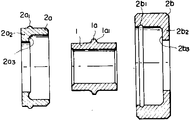
제1도는 본 발명의 한가지 실시예를 도시한 단면도.1 is a cross-sectional view showing one embodiment of the present invention.
제2도는 제1도의 분해 단면도.2 is an exploded cross-sectional view of FIG.
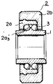
제3도는 본 발명의 다른 실시예를 도시한 단면도.3 is a cross-sectional view showing another embodiment of the present invention.
제4도는 제3도의 분해 단면도.4 is an exploded cross-sectional view of FIG.
제5도는 종래의 보올베어링의 단면도.5 is a cross-sectional view of a conventional bowl bearing.
* 도면의 주요부분에 대한 부호의 설명* Explanation of symbols for main parts of the drawings
1 : 내측레이스 2 : 외측레이스1: inner race 2: outer race
3 : 보올 la : 환상 돌출부3: bowl la: annular protrusion
2a : 제1컵부재 2b : 제2컵부재2a:
2a2, 2b2: 바닥벽 G : 환상실2a 2 , 2b 2 : Floor wall G: Annular room
본 발명은 래디얼 하중(radial load)뿐 아니라 드러스트 하중(thrust load)에도 충분히 견딜 수 있는 합성수지로 만들어진 보올 베어링에 관한 것이다.The present invention relates to a bowl bearing made of synthetic resin that can withstand not only a radial load but also a thrust load.
제5도에 도시된 바와같이 종래에는 합성수지로 만들어지고 내경부(a')를 갖는 내측 레이스(inner race, a)와 합성수지로 만들어진 외측 레이스(b)사이에 강철보올(c)이 2열로 배열되어 있다. 내측 레이스(a)는 서로 꼭맞게 되는 소직경 부분(a1)과 대직경부분(a2)으로 구성된다. 여러개의 강철보올(c)이 각 부분(a1, a2)의 서로 마주보고 있는 각 측벽(a3, a4)으로 이루어진 환상홈(G)내에 들어 있다. 강철보올(C)은 외측 레이스(b)내면의 중간부에 형성되어 있는 환상돌출부(b1)에 의하여 2열로 배치된다. 환상돌출부(b1)의 양측면(b2)은 강철보울(c)의 외면과 전체적으로 꼭맞게 접촉하도록 대체로 둥글게 성형되어 있다. 그러나, 이상과 같은 구조로는 외측 레이스(b)의 측벽부(b')의 크기가 내경부(a')에 축이 장착되는 내측레이스(a)에 비하여 작기 때문에, 드러스트 하중이 합성수지 베어링의 외측 레이스로 쉽게 전달되지 않는다. 특히 베어링이 작을 때에는 드러스트 하중의 전달이 거의 불가능하다.As shown in FIG. 5, conventionally, the steel balls c are arranged in two rows between an inner race a made of synthetic resin and having an inner diameter a 'and an outer race b made of synthetic resin. It is. The inner race a consists of a small diameter portion a 1 and a large diameter portion a 2 , which are fitted together. Several steel bowls (c) are contained in annular grooves (G) consisting of each of the side walls (a 3 , a 4 ) facing each other of the portions (a 1 , a 2 ). Steel bowls (C) are arranged in two rows by annular projections (b 1 ) formed in the middle portion of the inner surface of the outer race (b). Both sides (b 2 ) of the annular projection (b 1 ) is formed in a generally round shape so as to be in full contact with the outer surface of the steel bowl (c) as a whole. However, in the above structure, since the size of the side wall portion b 'of the outer race b is smaller than that of the inner race a in which the shaft is mounted on the inner diameter a', the thrust load is a synthetic resin bearing. It is not easily transferred to the outer race of the. Especially when the bearings are small, transfer of thrust loads is almost impossible.
마찬가지로 상기 구조에서는 보올(ball)표면의 직경이 크다. 그러므로 보올뿐 아니라 보올과 접촉하는 통로면의 마모도 크기 때문에 베어링의 사용 수명이 짧다. 또, 내측 레이스와 외측 레이스 사이의 공간이 전체 베어링이 바깥쪽 원주부분에 위치하므로 원심력에 의하여 내부의 그리이스가 누출된다.Likewise, in the above structure, the diameter of the ball surface is large. Therefore, the service life of the bearing is short because not only the bowl but also the wear of the passage face in contact with the bowl is large. In addition, since the space between the inner race and the outer race is located at the outer circumferential portion of the entire bearing, the grease inside leaks due to the centrifugal force.
또, 이 간격의 크기가 크기 때문에 방진(防塵)특성도 불량하다.In addition, since the size of this gap is large, the dustproof property is also poor.
따라서 본 발명의 목적은 종래의 베어링에 내포된 앞서 언급한 문제점이 없는 합성수지 베어링을 제공하려는 것이 다.It is therefore an object of the present invention to provide a synthetic bearing which is free from the above mentioned problems contained in conventional bearings.
상기 목적을 달성하기 위하여 제1컵부재와 제2컵부재가 포함되고, 컵부재는 각각 테두리단 및 하부단이 있는 환상벽과 상기 하부단으로부터 일체로 연장된 바닥벽을 가져 그 내부에 오목부가 형성되어 있으며, 상기 바닥벽의 중심에는 구멍이 형성되어 있고, 상기 제1컵부재는 제2컵부재의 상기 오목부내에 꼭맞게 결합되도록 크기가 정해지고, 제1컵부재의 상기 테두리단은 제2컵부재의 바닥벽과 접촉하며, 컵부재의 바닥벽에 각각 형성된 상기 구멍이 서로 일렬로 정렬되어 있는 합정수지 외측 레이스 ; 상기 구멍들을 통하여 외측레이스에 삽입되어, 상기 제1컵부재 및 제2컵 부재의 상기 바닥벽과 함께 환상실을 형성하며, 상기 환상실내로 돌출하는 환상 돌출부가 있어 한쌍의 보올수용부를 형성하는 환상의 합성수지 내측 레이스 ; 각 보올 수용부내에 수용되어 상기 내측 레이스둘레에 환상으로 배치되는 여러개의 보올로 이루어지는 합성수지보올 베어링이 제공된다.In order to achieve the above object, a first cup member and a second cup member are included, and the cup member has an annular wall having a rim end and a lower end, respectively, and a bottom wall integrally extending from the lower end. And a hole is formed in the center of the bottom wall, and the first cup member is sized to fit snugly within the recess of the second cup member, and the edge end of the first cup member is formed. A haptic resin outer race in contact with the bottom wall of the two cup members, the holes respectively formed in the bottom wall of the cup member aligned with one another; An annular chamber inserted into the outer race through the holes to form an annular chamber together with the bottom wall of the first cup member and the second cup member, and having an annular protrusion projecting into the annular chamber to form a pair of bowl accommodation portions; Synthetic resin inner race; There is provided a synthetic resin bearing comprising a plurality of bowls housed in each bowl receiving portion and annularly disposed around the inner race.
이하 첨부도면을 참조하여 본 발명의 바람직한 실시예를 설명하기로 한다.Hereinafter, exemplary embodiments of the present invention will be described with reference to the accompanying drawings.
제1도 및 제2도에서 부호(1)는 합성수지로 만들어진 환상의 내측 레이스이다. 상기 내측레이스에는 축이 삽입되는 내경부(1')가 형성되어 있다. 부호(2)는 마찬가지로 합성수지로 만들어져 외부 하중을 받는 외측 레이스이다. 외측 레이스(2)는 서로 결합되는 비교적 직경이 작은 제1컵부재(2a)와 비교적 직경이 큰 제2컵부재(2b)로 구성된다. 컵부재는 각각, 테두리단 및 하부단이 있는 환상벽과, 상기 하부단으로부터 일체로 연장된 바닥벽(2a22b2)을 가져 그 내부에 오목부가 형성된다. 상기바닥벽(2a2, 2b2)의 중심에는 구멍이 뚫려 있다. 상기 제1컵부재(2a)는 제2컵부재(2b)의 상기 오목부내에 꼭 맞게 결합되도록 크기가 정해진다. 조립된 상태에서 제1컵 부재(2a)의 테두리단은 제2컵부재(2b)의 바닥벽과 접촉한다. 컵부재의 바닥벽에 각각 형성된 상기 구멍들은 조립되었을때 서로 일렬로 정렬된다. 제1컵부재(2a)에는 환상의 돌기(2a1)가 형성되어 있는 반면 제2컵부재(2b)에는 환상 오목부(2b1)가 서로 반대위치에 형성되어 서로 결합된다. 상기 내측레이스(1)는 각각의 컵부재(2a, 2b)의 바닥벽에 있는 구멍들을 통하여 연장되도록 위치하여 제1컵부재 및 제2컵부재의 바닥벽과 함께 환상실(G)을 형성한다.In Fig. 1 and Fig. 2,
내측 레이스(1)의 외주의 중심부에는 환상돌출부(1a)가 형성되어 있다. 돌출부(1a)는 조립되었을때 서로 대향하는 외측 레이스(2)의 바닥벽(2a2, 2b2)에 의하여 형성된 환상실(G)내로 돌출하여 여러개의 강철보올(3)이 수용되는 환상실(G)을 2열의 보올수용부로 분리시킨다. 환상돌출부(la)의 양측면에는 한쌍의 둥근 안내면(1a1)이 형성되어 있다. 안내면(la1)은 보올(3)과 합치되도록 설계되어 있다. 마찬가지로, 직경이 작은 제1컵부재(2a)의 내면에도 보올(3)과 합치되도록 상기 내측 레이스 주위에 환상으로 연장된 둥근 안내면(2a3)이 형성되어 있다.An annular projection 1a is formed at the center of the outer circumference of the
위의 실시예에서, 직경이 작은 제1컵부재(2a)와 직경이 큰 제2컵부재(2b)는 환상돌기부(2a1)를 환상오목부(2b1)에 압입시켜 서로 결합된다. 이 대신에 에폭시 접착제, 초음파 용접등을 이용한 다른 결합수단이나 나사, 유도가열브레이징(induction brazing) 또는 열선 용접(hot-wire welding)등을 이용한 기계적결합 수단을 이용하여 제1 및 제2컵부재(2a, 2b)의 결합을 유지시킬 수도 있다. 이상과 같은 구조로 하여 내측 레이스(1)와 외측 레이스(2)사이에 형성된 각각의 수용부에 여러개의 강철보올(3)을 채우면 보올(3)들은 2열로 배열된다. 보올(3)들은 각각 내측 레이스(1)의 환상돌출부(1a)의 둥근 안내면(1a1)과 외측 레이스(2)의 바닥벽(2a2, 2b2)의 내면(2a3, 2b3)에 접촉하여 지지된다.In the above embodiment, the first cup member 2a having a small diameter and the
베어링이 위에서 설명한 것과 같은 구조를 가지면 드러스트 하중은 전적으로 외측 레이스(2)의 넓은 측벽부(2')로 전달된다.If the bearing has a structure as described above, the thrust load is transmitted entirely to the wide sidewall portion 2 'of the
이 실시예에서, 제1컵부재의 바닥벽에는 원호상으로 연장된 내면이 형성되어 있다.In this embodiment, an inner surface extending in an arc shape is formed in the bottom wall of the first cup member.
제3도 및 제4도에 도시된 실시예에서는 직경이 작은 제1컵부재(2a)의 바닥벽의 내측 안내면에 둥근 안내면이 형성되어 있지 않는 대신 상기 내측면이 대체로 평평하게 연장되어 있다. 그러나, 상기 내면은 구멍의 근처에서 서서히 상승하기 시작하여 환상돌출부(2a3')가 형성되어 있다. 이같은 등근 안내면(2a3') 또는 환상돌출부(2a3')는 조립시 강철보올이 떨어지는 것을 방지해 준다.In the embodiment shown in FIGS. 3 and 4, a round guide surface is not formed on the inner guide surface of the bottom wall of the first cup member 2a having a small diameter, and the inner surface extends substantially flat. However, the inner surface starts to rise gradually in the vicinity of the hole, and an annular projection 2a 3 'is formed. Such a back guide surface (2a 3 ') or annular projection (2a 3 ') to prevent the falling of the steel bowl during assembly.
이상 설명한 대로 본 발명에 의한 베어링은, 축이 삽입되는 구멍이 뚫려 있으며 그 외주면의 중심부에 여러개의 강철보올이 2열로 배치되도록 양측면에 둥근 안내면이 있는 환상돌출부가 형성되어 있는 내측 레이스와, 서로 결합되도록 환상돌기와 환상오목부가 서로 대향하여 형성되어 있는 비교적 직경이 작은 제1컵부재와 비교적 직경이 큰 제2컵부재로 구성되어 상기 제1 및 제2컵부재의 바닥벽에 의하여 보올들이 수용되는 환상실이 형성되어 있는 외측 레이스와, 조립되었을때, 내측 레이스의 외주면의 상기 환상돌출부의 양쪽에서 환상돌출부의 둥근안내면과 바닥벽에 접촉하도록 외측 레이스의 환상실내에 위치하는 보올들로 이루어진다. 내구성을 증대시키기 위하여 보올이 2열로 배치되어 래디얼 하중과 드러스트 하중을 받는 이 합성수지 베어링에서, 외측 레이스의 바닥벽이 현저히 커진 구조에 의하여 외측 레이스의 바닥벽에 의하여 충분한 드러스트 하중을 받을 수 있다. 이 경우에 바닥벽이 보올에 의하여, 직접 지지되도록 설계되었기 때문에 충분한 강도나 내구성을 유지할 수 있다.As described above, the bearing according to the present invention has an inner race having a hole in which a shaft is inserted and an annular protrusion having round guide surfaces formed on both sides thereof so that several steel balls are arranged in two rows at the center of the outer circumferential surface thereof. A ring having a relatively small first cup member and a second cup member having a relatively large diameter, wherein the annular projection and the annular recess are formed to face each other so that the bowls are accommodated by the bottom walls of the first and second cup members. An outer race in which a thread is formed and, when assembled, a bowl positioned in the annular chamber of the outer race so as to contact the round guide surface of the annular protrusion and the bottom wall on both sides of the annular protrusion of the outer circumferential surface of the inner race. In this synthetic bearing, which has two rows of bowls and is subjected to radial and thrust loads for increased durability, the bottom wall of the outer race can be subjected to sufficient thrust load by the bottom wall of the outer race due to the significantly larger structure. . In this case, since the bottom wall is designed to be directly supported by the bowl, sufficient strength and durability can be maintained.
또 보올이 이동하는 원주면의 직경이 작기 때문에 보올의 원주속도가 느리다. 이에 따라 보올의 마모뿐 아닌라 보올과 접촉하는 통로면의 마모도 감소되어 베어링의 사용수명을 연장시킬 수 있다. 또, 내측 레이스와 외측 레이스 사이의 공간이 전체 베어링의 안쪽 원주부분에 위치하므로 원심력의 영향이 줄어들어 그리이스가 튀어 나오는 것을 방지할 수 있다. 마찬가지로 간격의 크기가 작기 때문에 방진(防塵)특성도 개선된다.In addition, the circumferential speed of the bowl is slow because the diameter of the circumferential surface on which the bowl moves is small. Accordingly, not only the wear of the bowl but also the wear of the passage face contacting the bowl can be reduced, thereby extending the service life of the bearing. In addition, since the space between the inner race and the outer race is located at the inner circumference of the whole bearing, the influence of the centrifugal force is reduced, and grease can be prevented from popping out. Similarly, since the size of the gap is small, the dustproofing property is also improved.
뿐만 아니라, 내측 레이스가 일체로 구성되므로 베어링의 정밀도가 극히 우수하고 안정되며, 내측 레이스의 두께가 비교적 얇기 때문에 회전으로 인하여 내측에서 발생한 열이 용이하게 축으로 방출된다. 또, 회전하는 동안의 진동과 소음이 외측 레이스로 흡수되고, 앞서 설명한 대로 내외측 레이스 사이의 공간이 작기 때문에 작동중의 소음을 줄일 수 있다.In addition, since the inner race is integrally formed, the precision of the bearing is extremely excellent and stable, and because the thickness of the inner race is relatively thin, the heat generated from the inside due to the rotation is easily released to the shaft. In addition, vibration and noise during rotation are absorbed by the outer race, and the noise during operation can be reduced because the space between the inner and outer races is small as described above.
비록 본 발명는 바람직한 실시예를 참고하여 기술되었지만 본 발명의 정신내에서 여러가지 순정과 변경을 가할 수 있다.Although the present invention has been described with reference to preferred embodiments, various changes and modifications can be made within the spirit of the invention.
Claims (5)
Applications Claiming Priority (3)
| Application Number | Priority Date | Filing Date | Title |
|---|---|---|---|
| JP14432484A JPS6124819A (en) | 1984-07-13 | 1984-07-13 | Bearing made of synthetic resin |
| JP59-144324 | 1984-07-13 | ||
| JP144324 | 1984-07-13 |
Publications (2)
| Publication Number | Publication Date |
|---|---|
| KR860001303A KR860001303A (en) | 1986-02-24 |
| KR890000320B1 true KR890000320B1 (en) | 1989-03-14 |
Family
ID=15359450
Family Applications (1)
| Application Number | Title | Priority Date | Filing Date |
|---|---|---|---|
| KR1019850005009A KR890000320B1 (en) | 1984-07-13 | 1985-07-13 | Synthetic resin ball bearing |
Country Status (6)
| Country | Link |
|---|---|
| US (1) | US4606657A (en) |
| EP (1) | EP0168791A1 (en) |
| JP (1) | JPS6124819A (en) |
| KR (1) | KR890000320B1 (en) |
| AU (1) | AU569014B2 (en) |
| CA (1) | CA1233498A (en) |
Families Citing this family (25)
| Publication number | Priority date | Publication date | Assignee | Title |
|---|---|---|---|---|
| DE3536796A1 (en) * | 1985-10-16 | 1987-04-16 | Kugelfischer G Schaefer & Co | DOUBLE-ROW ROLLER BEARING, ESPECIALLY FOR MOTORCYCLE WHEELS |
| US4806024A (en) * | 1986-10-31 | 1989-02-21 | Tanashin Denki Co., Ltd. | Rotatably supporting structure |
| JPH01140022U (en) * | 1988-03-18 | 1989-09-25 | ||
| US4919120A (en) * | 1988-06-09 | 1990-04-24 | Sanyo Electric Co., Ltd. | Radiant-type heater |
| US4919552A (en) * | 1988-06-27 | 1990-04-24 | Industria Plastica Ramos S.A. | Machine bearing |
| US5136777A (en) * | 1988-12-03 | 1992-08-11 | Skf Gmbh | Attachment of a hard bearing ring to the bore surface of a housing or to the lateral surface of a journal |
| DE3840869C2 (en) * | 1988-12-03 | 1997-08-14 | Skf Gmbh | Arrangement for fastening a hard bearing ring in the bore surface of a housing or on the outer surface of a pin |
| DE3940274A1 (en) * | 1989-12-06 | 1991-06-13 | Esjot Antriebstech Gmbh & Co | BOTTOM BEARING UNIT FOR INSTALLATION IN BOTTOM BEARING HOUSING OF BICYCLES OR THE LIKE AND METHOD FOR ASSEMBLING THE BOTTOM BRACKET UNIT |
| US4997293A (en) * | 1990-03-22 | 1991-03-05 | Nippon Sharyo Seizo Kabushiki Kaisha | Anti-electrolytic corrosion type rolling bearing |
| DE4101014C2 (en) * | 1991-01-15 | 1993-10-07 | Hoermann Kg | Roller device for guiding door leaves |
| CA2076481C (en) * | 1991-08-26 | 1998-11-03 | Jimmy L. Hicks | Shopping cart wheels with polymeric bearing races |
| BE1006348A3 (en) * | 1992-11-16 | 1994-07-26 | Peter Goegebeur | Integrated roller bearing intended for mounting a wheel hub and applicationfor wheelbarrow wheels. |
| DE10129700A1 (en) * | 2001-01-26 | 2002-08-01 | Continental Teves Ag & Co Ohg | Ball bearing for vehicle wheel has inner ring with radial arms on which second inner ring is mounted which is held in position by arms |
| US6553618B2 (en) | 2001-05-01 | 2003-04-29 | Overhead Door Corporation | Dual durometer roller guide member for track guided door |
| DE10220419A1 (en) * | 2002-05-08 | 2003-11-20 | Skf Ab | Roller bearing has injection molded plastic inner and outer rings each with a rim at one side and a separately molded rim closes the other side |
| CA2603390A1 (en) * | 2007-09-26 | 2009-01-12 | Mark Zlipko | Non-diametrical multi-contact bearing |
| CN101554868B (en) * | 2008-04-08 | 2012-05-30 | 黄潭城 | Anti-lock brake structure |
| KR101059374B1 (en) * | 2011-03-24 | 2011-08-25 | (주)연합시스템 | Radial bearing |
| DE102012108819A1 (en) * | 2012-09-19 | 2014-03-20 | Nordischer Maschinenbau Rud. Baader Gmbh + Co. Kg | Rolling and rotary device with roller bearings |
| RU2523357C1 (en) * | 2012-12-05 | 2014-07-20 | Федеральное государственное бюджетное образовательное учреждение высшего профессионального образования "Алтайский государственный технический университет им И.И. Ползунова" (АлтГТУ) | Ball cageless bearing |
| US9188107B2 (en) * | 2013-08-30 | 2015-11-17 | General Electric Company | Wind turbine bearings |
| RU2570891C1 (en) * | 2014-07-30 | 2015-12-10 | Федеральное государственное бюджетное образовательное учреждение высшего профессионального образования "Алтайский государственный технический университет им. И.И. Ползунова" (АлтГТУ) | Ball cageless roll bearing |
| US10391645B2 (en) * | 2015-11-25 | 2019-08-27 | Southern Grind, Inc. | Multi-track bearing folding knife |
| US11401968B2 (en) * | 2017-01-23 | 2022-08-02 | Dana Automotive Systems Group, Llc | Snap-in bearing cup |
| DE102018125316A1 (en) | 2018-10-12 | 2020-04-16 | B. Braun Melsungen Ag | Double row roller bearing unit with preload element |
Family Cites Families (16)
| Publication number | Priority date | Publication date | Assignee | Title |
|---|---|---|---|---|
| US1353874A (en) * | 1919-10-20 | 1920-09-28 | Peter C Wego | Bearing for conveyer-rollers |
| US1546363A (en) * | 1922-02-23 | 1925-07-21 | Beemer Frank | Antifriction bearing |
| US1615810A (en) * | 1922-04-10 | 1927-01-25 | Kas So Kitch E Mon E Too So Ne | Breech-lock bearing |
| US2614898A (en) * | 1948-12-14 | 1952-10-21 | Charles A Adams | Ball bearing |
| GB1095994A (en) * | 1963-08-09 | 1967-12-20 | Minerva Lab Instr Ltd | Roller wheel and bearing assembly |
| FR1466602A (en) * | 1964-12-18 | 1967-01-20 | Dowty Seals Ltd | Improvements to sets of ball or roller bearings |
| DE1575490B2 (en) * | 1966-12-30 | 1972-03-23 | Happe & Co, 5606 Tonisheide | ROLLER IN PARTICULAR FOR ROELLCHEN CONVEYOR RAILWAYS |
| US3722968A (en) * | 1967-06-29 | 1973-03-27 | Nat Bearings Co | Wheel-bearing assembly |
| DE2124247A1 (en) * | 1971-05-15 | 1972-11-30 | Schaeffler Ohg Industriewerk | Double row angular contact ball bearing |
| DE2234984C3 (en) * | 1972-07-17 | 1975-04-10 | Deutsche Star Kugelhalter Gmbh, 8720 Schweinfurt | Double row rolling bearing with split inner race |
| GB1434940A (en) * | 1972-12-05 | 1976-05-12 | Bearings Non Lube Ltd | Ball bearings |
| DE7638967U1 (en) * | 1976-12-13 | 1977-04-21 | Skf Kugellagerfabriken Gmbh, 8720 Schweinfurt | Sealed drive roller |
| JPS5517252A (en) * | 1978-07-20 | 1980-02-06 | Trio Kenwood Corp | Control circuit for motor |
| IT1144121B (en) * | 1981-02-27 | 1986-10-29 | Riv Officine Di Villar Perosa | SUPPORT COMPLEX FOR VEHICLE WHEELS |
| JPS5959528U (en) * | 1982-10-13 | 1984-04-18 | ダイトク産業株式会社 | bearing |
| DE3239058A1 (en) * | 1982-10-22 | 1984-04-26 | Uni-Cardan Ag, 5200 Siegburg | WHEEL HUB BEARING ARRANGEMENT |
-
1984
- 1984-07-13 JP JP14432484A patent/JPS6124819A/en active Granted
-
1985
- 1985-07-12 CA CA000486756A patent/CA1233498A/en not_active Expired
- 1985-07-12 EP EP85108722A patent/EP0168791A1/en not_active Ceased
- 1985-07-12 AU AU44846/85A patent/AU569014B2/en not_active Ceased
- 1985-07-12 US US06/754,224 patent/US4606657A/en not_active Expired - Lifetime
- 1985-07-13 KR KR1019850005009A patent/KR890000320B1/en not_active IP Right Cessation
Also Published As
| Publication number | Publication date |
|---|---|
| KR860001303A (en) | 1986-02-24 |
| JPS6124819A (en) | 1986-02-03 |
| AU4484685A (en) | 1986-01-16 |
| US4606657A (en) | 1986-08-19 |
| CA1233498A (en) | 1988-03-01 |
| AU569014B2 (en) | 1988-01-14 |
| EP0168791A1 (en) | 1986-01-22 |
| JPH0428929B2 (en) | 1992-05-15 |
Similar Documents
| Publication | Publication Date | Title |
|---|---|---|
| KR890000320B1 (en) | Synthetic resin ball bearing | |
| US6371655B1 (en) | Housing device for a ball-type rolling bearing and associated rolling bearing | |
| US6290471B1 (en) | Pivotal structure for an impeller of a miniature heat dissipating fan | |
| US4910424A (en) | Bearing retainer for dynamoelectric motor | |
| US4606655A (en) | Roller bearing | |
| US4204717A (en) | Ball bearing with radial apertures in end rings | |
| JPH0676807B2 (en) | Linear ball bearing | |
| JPS61266822A (en) | Ball spline bearing | |
| US20040126040A1 (en) | Fluid dynamic bearing module | |
| KR20010042054A (en) | Cage for a ball bearing, and ball bearing comprising such cage | |
| US6310415B1 (en) | Bearing structures for a motor rotor | |
| JP3602707B2 (en) | Hydrodynamic bearing motor | |
| US6175547B1 (en) | Positive and negative rotation gas dynamic pressure bearing, spindle motor having dynamic pressure bearing, and rotator device having spindle motor as driving source | |
| US6149412A (en) | Rotation preventing mechanism using thrust ball bearing and scroll type compressor using the same | |
| JP2000320558A (en) | Synthetic resin made retainer for roller bearing | |
| JP2566658Y2 (en) | Motor bearing device | |
| CN211624141U (en) | Gear fixing precision mechanism | |
| US4149760A (en) | Snap cage of synthetic material | |
| CN216904466U (en) | Rotor assembly and brushless coreless cup motor | |
| JP3503794B2 (en) | motor | |
| KR102295186B1 (en) | Bearing assembly | |
| JPS635624B2 (en) | ||
| JPH0518496Y2 (en) | ||
| WO1999056029A1 (en) | Cage with improved mass distribution, and ball bearing comprising such cage | |
| KR100222828B1 (en) | Ball bearing retainer |
Legal Events
| Date | Code | Title | Description |
|---|---|---|---|
| A201 | Request for examination | ||
| G160 | Decision to publish patent application | ||
| E701 | Decision to grant or registration of patent right | ||
| GRNT | Written decision to grant | ||
| FPAY | Annual fee payment |
Payment date: 19970829 Year of fee payment: 16 |
|
| LAPS | Lapse due to unpaid annual fee |