KR890000143B1 - Intergrated weblocker with programm pawl retractor - Google Patents
Intergrated weblocker with programm pawl retractor Download PDFInfo
- Publication number
- KR890000143B1 KR890000143B1 KR1019830004357A KR830004357A KR890000143B1 KR 890000143 B1 KR890000143 B1 KR 890000143B1 KR 1019830004357 A KR1019830004357 A KR 1019830004357A KR 830004357 A KR830004357 A KR 830004357A KR 890000143 B1 KR890000143 B1 KR 890000143B1
- Authority
- KR
- South Korea
- Prior art keywords
- belt
- seat belt
- detent
- reel
- frame
- Prior art date
Links
Images


Classifications
-
- B—PERFORMING OPERATIONS; TRANSPORTING
- B60—VEHICLES IN GENERAL
- B60R—VEHICLES, VEHICLE FITTINGS, OR VEHICLE PARTS, NOT OTHERWISE PROVIDED FOR
- B60R22/00—Safety belts or body harnesses in vehicles
- B60R22/34—Belt retractors, e.g. reels
- B60R22/36—Belt retractors, e.g. reels self-locking in an emergency
- B60R22/42—Belt retractors, e.g. reels self-locking in an emergency having means for acting directly upon the belt, e.g. by clamping or friction
Abstract
Description
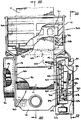
제1도는 본 발명의 대표적인 실시예가 합체된 안전 벨트 견인기의 일부 절개 정면도.1 is a partial cutaway front view of a seat belt retractor incorporating a representative embodiment of the present invention.
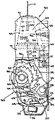
제2도는 제1도에 도시한 안전벨트 견인기를 Ⅱ-Ⅱ면을 따라 절단한 일부 절개 측면도.FIG. 2 is a partial cutaway side view of the seat belt retractor shown in FIG. 1 taken along plane II-II; FIG.
제3도는 제1도에 도시한 안전벨트 견인기를 Ⅲ-Ⅲ면을 따라 절단한 부분 단면도.3 is a partial cross-sectional view taken along the III-III plane of the seat belt retractor shown in FIG.
제4도는 제1도에 도시한 안전벨트 견인기를 제2도의 Ⅳ-Ⅳ면을 따라 절단한 부분 단면도.4 is a partial cross-sectional view of the seat belt retractor shown in FIG. 1 taken along the IV-IV plane of FIG.
제5도는 제2도와 유사한 도면으로, 안전벨트 견인기가 잠김상태에 있는 것을 도시한 부분 절개 측면도.FIG. 5 is a view similar to FIG. 2, with a partial cutaway side view showing the seat belt retractor in a locked state. FIG.
제6도는 제3도와 유사한 도면으로, 제1도에 도시한 안전벨트 견인기가 잠김상태에 있는 것을 도시한 부분 단면도.FIG. 6 is a view similar to FIG. 3, with a partial cross-sectional view showing that the seat belt retractor shown in FIG. 1 is locked.
* 도면의 주요 부분에 대한 부호의 설명* Explanation of symbols for the main parts of the drawings
10 : 안전벨트 견인기 11 : 안전벨트10: seat belt retractor 11: seat belt
12 : 견인기 프레임 20 : 톱니멈춤쇠 조립체12: retractor frame 20: detent assembly
30 : 릴 조립체 50 : 벨트 고정구30 reel assembly 50 belt fastener
본 발명은 일반적으로 차량에 비상사태가 발생했을 경우에 차내의 승객을 좌석에 구속시키기 위하여 사용하는 안전벨트 견인기용 비상잠김 장치에 관한 것으로, 특히 안전벨트를 감는 릴이 부착된 단일 안전벨트 견인기용의 단일 관성 감지수단을 이용하는 벨트 고정 및 릴 잠김장치에 관한 것이다.BACKGROUND OF THE INVENTION Field of the Invention [0001] The present invention relates generally to an emergency locking device for seatbelt retractors used to restrain passengers in a car to a seat in case of an emergency in a vehicle, in particular for a single seatbelt retractor with a reel winding the seatbelt. A belt fastening and reel locking device using a single inertial sensing means of.
안전벨트 구속장치, 특히 관성 감지식 잠김수단이 부착된 안전벨트 구속장치는 본 기술분야에 이미 공지된 것이다. 본 업계에서는 작동 부품의 수가 적고 가격이 저렴하면서도 승객이 이용하기에 불편이 없는 안전벨트 구속장치를 개발하려는 부단한 노력이 계속되고 있다.Seat belt restraints, in particular seat belt restraints with inertial sensing locking means, are already known in the art. The industry continues to develop safety belt restraints that have fewer moving parts, are less expensive, and are more comfortable for passengers.
종래 형태의 스풀잠김식 견인기에 있어서는 비상사태가 발생하여 스풀 자체가 고정된다 할지라도 스풀에 잠겨 있는 벨트가 조여지면서 어느 정도의 벨트 이완이 발생하는 결점이 있었다. 즉, 벨트가 감겨 있는 층이 조밀해지면서 일정량의 벨트가 늘어나는 것이다.In the conventional spool-locked retractor, even if an emergency occurs and the spool itself is fixed, there is a drawback that some belt relaxation occurs as the belt locked in the spool is tightened. In other words, as the layer on which the belt is wound becomes dense, a certain amount of the belt is stretched.
본 발명의 목적은 관성 감지수단의 작동에 대응하여 견인기 스풀이 고정되고 관성감지 수단과 연동되는 제2의 고정기구에 의해서 안전벨트의 이완이 방지되도록 한 단일 관성감지 수단 작동식 이중 벨트 고정 장치를 제공하는 것이다.It is an object of the present invention to provide a single inertial sensing means actuated dual belt fixing device in which the retractor spool is fixed in response to the operation of the inertial sensing means and the seat belt is prevented from being relaxed by a second fixing mechanism interlocked with the inertial sensing means. To provide.
차체에 고정된 프레임과, 프레임에 회전가능하게 조립된 벨트 감김릴과, 전기한 릴에 부착되며 다수의 톱니가 가공된 래칫휘일과, 비상 사태가 발생하면 래칫휘일과 맞물려서 벨트가 풀리는 것을 방지하는 관성 감지식 톱니멈춤쇠와, 프레임에 장착된 클램핑 수단으로 구성되어 전기한 클램핑 수단 사이를 통과하는 벨트를 선택적으로 고정하는 안전벨트 고정구 등으로 구성된 관성감지식 안전벨트 잠김 장치에 있어서, 전기한 관성 감지식 톱니멈춤쇠를 구성요소로 하며 견인기 프레임과는 상대적으로 정지위치와 작동위치 사이의 제한된 회전 운동을 하는 톱니멈춤쇠 조립체를 제공함으로써, 전기한 관성 감지식 톱니멈춤쇠가 전기한 래칫휘일과 맞물리거나 안전벨트에 작용하는 이완력이 최하치를 초과하면 전기한 톱니멈춤쇠 조립체가 작동위치로 회전하고, 그에 따라 벨트고정구 작동기가 작동하여 클램프 수단 사이를 통과하는 벨트를 즉각적으로 고정하는 본 발명에 따른 장치에서는 상기의 목적을 달성 할 수 있다.A frame fixed to the vehicle body, a belt winding reel rotatably assembled to the frame, a ratchet wheel attached to the electric reel and a plurality of teeth processed, and a ratchet wheel engaged with the ratchet wheel in case of an emergency to prevent the belt from loosening An inertial sensing seat belt locking device comprising an inertial sensing tooth detent and a seat belt fastener configured to selectively fix a belt passing between the clamping means, which is composed of clamping means mounted on the frame, By providing a detent assembly, which is a component of the sense detent and which has a limited rotational movement between the stop and actuation positions relative to the retractor frame, the inertial sense detents described above If the loosening force engaged or engaged on the seatbelt exceeds the minimum, the toothed detent assembly will move to the operating position. In the apparatus according to the invention, rotation, and by a belt fastener actuator operation immediately fixed to the belt passing between the clamping means accordingly it is possible to achieve the above object.
먼저 제1도와 제2도를 보면 본 발명의 장치가 부착된 안전벨트 견인기(10)가 도시되어 있다. 안전벨트 견인기(10)는 차량의 도어 포스트등과같이 편리한 장소에 고정할 수 있도록 되어 있는 프레임(12)으로 구성된다. 관성 작동식 톱니멈춤쇠 조립체(20)는 후술하는 바와 같이 프레임(12)에 대하여 상대적인 회전운동이 가능하도록 장착된다. 즉, 톱니멈춤쇠 조립체(20)는 견인기 프레임(12)의 두측벽(13,14)사이에 위치한 중심핀들(31)로 구성되는 릴 조립체(30)에 연결된다. 이때 중심 스핀들은 안전벨트(11)를 감는 스풀기능을 한다. 릴 조립체(30)는 견인기 프레임(12)의 평행측벽(13,14)을 관통하여 그곳에 축받이된 축부(34,35)로 구성된다. 또한, 한쪽의 축부(5)에는 주관성감지식 잠김장치용의 주 래칫휘일 역할을 하는 래칫 휘일(32)이 부착된다.First and secondly, there is shown a seatbelt retractor 10 to which the device of the present invention is attached. The seat belt retractor 10 is composed of a
축부(35)와 저어널면(21,22)에 의해 프레임(12)에 대하여 상대적인 회전운동이 가능하도록 장착된 관성 작동식 톱니멈춤 조립체(20)는 제2도에 도시한 정지위치와 제5도에 도시한 작동위치 사이에서 제한된 회전운동을 한다. 견인기 프레임(12)내에는 스프링(도시되지 않음)이 내설되어 관성 작동식 톱니멈춤쇠 조립체(20)를 정지위치로 복원시키려는 힘을 가한다. 이 스프링이 갖고 있는 스프링 력에 의해서 톱니멈춤쇠 조립체(20)가 작동위치로 회전하기 위하여 안전벨트(11)에 가해져야 하는 이완력의 최소치가 결정된다. 이러한 스프링력과 스프링력에 의한 톱니멈춤쇠 조립체의 회전 효과에 대하여는 차후에 상세히 설명할 것이다.The inertial actuating tooth stop assembly 20 mounted by the
안전벨트(11)는 릴 조립체(30)의 스핀들(31)에 감겨 있다. 스핀들에 감긴 안전벨트(11)가 이완력에 의해 풀려나가면 견인기 프레임(12)의 하우징(16)에 내설된 스프링(15)이 더욱 강하게 조여지기 때문에 이완력이 제거됨과 도시에 릴 조립체(30)가 역방향으로 회전하여 안전벨트(11)를 되감는다. 제2도에 도시한 안전벨트(11)역시 이완력이 작용하면 릴 조립체에 반시계 방향의 회전운동을 유발시킬 수 있도록 스핀들(31)에 감겨 있다. 톱니멈춤쇠 조립체(20)는 상기의 릴 조립체와 같이 제2도에 도시한 정지위치로부터 제5도에 도시한 작동위치로 제한된 반시계 방향의 회전운동을 한다.The seat belt 11 is wound around the
또한 톱니멈춤쇠 조립체(20)는 릴 조립체(30)의 주 래칫휘일(32)에 가공된 다수의 톱니(36)와 맞물릴 수 있도록 배열된 주 톱니멈춤쇠(25)로 구성된다. 비상사태가 발생하면 상기의 주 톱니멈춤쇠는 관성질량체(26)에 작용하는 소정치 이상의 관성력에 대응하여 전기한 톱니와 맞물림으로써 릴 조립체(30)가 벨트의 풀림 방향으로 회전하는 것을 방지한다.The detent assembly 20 also consists of a
특히, 릴 조립체(30)에는 본 발명의 프로그램 톱니멈춤쇠와 조합 작동되는 프로그램 래칫휘일(33)이 부착되어 있는데, 상기의 프로그램 래칫휘일은 축부(35)상에서 주 래칫휘일(32)과 인접하게 설치된다. 주 래칫휘일(32)가 마찬가지로 프로그램 래칫휘일(33)의 외주면에는 다수의 톱니(36)가 가공되어 있다. 그러나 프로그램 래칫휘일(33)은 실시예에서 사용한 델린(Delrin)등과 같이 무게가 가볍고 가격이 저렴한 탄성 종합재료 제조한다. 관성 작동식 톱니멈춤쇠 조립체(20)내에는 구멍(27)이 가공된 주 톱니멈춤쇠(25)가 부착되어 있다. 전기한 주 톱니멈춤쇠(25)는 포스트(28)에 의해서 톱니멈춤쇠 조립체의 프레임(23)에 조립된다. 이와같이 포스트(28)에 피봇된 주 톱니멈춤쇠(25)는 릴 조립체(30)의 중심방향으로 접근 및 이탈 운동을 하면서 주 래칫휘일(32)의 톱니(36)와 선택적으로 맞물린다.In particular, the reel assembly 30 is attached with a
프로그램 톱니멈춤쇠(40) 역시 톱니멈춤쇠 조립체(20)의 프레임(23)에 조립된다. 즉, 피봇(29)에 의해 프로그램 톱니멈춤쇠(40) 자체에 가공된 피봇구멍(41)을 통하여 프레임(23)에 축선회 가능하게 장착되는 것이다. 이와같이 프레임에 피봇된 프로그램 톱니멈춤쇠(40)의 맞물림면(44)은 릴 조립체(30)의 중심방향으로 접근 및 이탈 운동을 하면서 프로그램 래칫휘일(33)의 톱니(36)와 선택적으로 맞물린다. 또한 프로그램 톱니멈춤쇠(40)에는 소정의 최하치를 초과하는 차량의 관성력이 관성 감지기에 작용할 경우에 진자(26) 또는 기타 관성 감지기의 헤드와 접촉하여 프로그램 톱니멈춤쇠(40) 자체가 피봇(29)을 중심으로 선회운동을 하도록 하는 돌출부(45)가 형성되어 있다. 프로그램 톱니멈춤쇠(40)의 절개부(42)에는 축방향으로 돌출된 주 톱니멈춤쇠(25)의 설상체(43)가 수용된다. 프로그램 래칫휘일(33)과 마찬가지로 프로그램 톱니멈춤쇠(40) 역시 델린(Derin)등과 같이 무게가 가볍고 가격이 저렴한 탄성 중합재로 만든다.The program detent 40 is also assembled to the
톱니멈춤쇠 조립체의 프로그램 특성에 따라 주 관성 감지기가 작동되는 순서는 다음과 같다. 소정의 최하치를 초과하는 차량의 관성력이 관성 질량체 또는 진자(26)에 가해지면, 상기의 진자가 기울어 지면서 프로그램 톱니멈춤쇠(40)의 돌출부(45)에 상승압력을 가한다. 피봇(29)에 의해 톱니멈춤쇠 조립체의 프레임(23)에 피봇된 프로그램 톱니멈춤쇠(40)는 이러한 상승압력으로 인하여 선회하게 되고, 그에 따라 프로그램 톱니멈춤쇠(40)의 맞물림면(44)이 프로그램 래칫휘일(33)의 톱니(36)와 맞물린다. 이와같이 맞물림 상태에서 안전벨트(11)가 약간만 늘어나도 래칫휘일(30)은 벨트의 이완에 상당하는 양만큼의 반시계 방향회전을 하게 된다. 래칫휘일의 반시계방향회전에 따라 프로그램 톱니멈춤쇠(40)는 피봇(29)을 기점으로 추가적인 선회운동을 하게되고 그에따라 절개부(42)의 하면에 수용된 주 톱니멈춤쇠(25)의 설상체(43)가 상승되면서 포스트(28)에 피봇된 주 톱니멈춤쇠와 주 래칫휘일(32)의 톱니(36)가 맞물린다. 주 톱니멈춤쇠(25)와 주 래칫휘일(32)은 금속등과 같은 강성재료로 되어 있기때문에 릴조립체(39)가 효과적으로 고정되어 풀림방향의 회전이 방지된다. 안전벨트의 풀림을 방지하는 이중잠김 장치의 첫번째 잠김지능은 이상과 같다.The order of operation of the main inertia detector according to the program characteristics of the detent assembly is as follows. When the inertial force of the vehicle exceeding the predetermined lower limit is applied to the inertial mass or the pendulum 26, the pendulum is inclined to exert an upward pressure on the protrusion 45 of the program detent 40. The program detent 40 pivoted by the pivot 29 to the
릴 조립체(30)에 접선방향으로 감겨 있는 안전벨트(11)에 추가적인 이완력이 작용하면 톱니멈춤쇠 조립체(20) 전체에 반시계 방향의 회전력 또는 모멘트가 발생한다. 이렇게 발생된 모멘트가 소정치 이상이 될 경우에는, 시계 방향으로 작용하는 톱니멈춤쇠 조립체 스프링의 스프링력이 상쇄됨과 동시에 톱니멈춤쇠 조립체(20) 전체가 견인기 프레임(12)의 저어널면(21,22)과 축부(35)를 지점으로 하여 정지 위치(제2도)로부터 작동위치(제5도)로의 반시계 방향회전을 한다. 작동위치에서는 톱니멈춤쇠 조립체(20)의 프레임(23) 선단(48)이 견인기 프레임(12)의 내면(49)과 접하게 되므로 더 이상의 반시계 방향 회전이 방지된다.When an additional relaxation force is applied to the seat belt 11 tangentially wound on the reel assembly 30, a rotational force or moment in the counterclockwise direction is generated in the entire detent assembly 20. When the generated moment is greater than or equal to the predetermined value, the spring force of the detent assembly spring acting in the clockwise direction is canceled and at the same time, the entire detent assembly 20 is closed on the journal surface 21 of the
본 발명에 따른 제2의 잠김장치는 제3도 및 제6도에 도시된 것과 같은 통합형 벨트고정구(50)로 구성된다. 벨트 고정구는 견인기 릴 조립체(30)의 전방, 즉 견인기 조립체(30)와 승객 사이에 위치하게되므로 안전벨트(11)가 릴 조립체(30)로부터 벨트 고정구(50)를 경유하여 승객에게로 풀려나가게 된다. 벨트 고정구(50)는 안전벨트(11)를 직접적이고 확실한 방법으로 고정하여 더 이상의 상대 운동이 발생하지 않도록 하는 견인기의 프레임(12)에 장착된 클램핑 수단으로 구성된다. 구체적으로 말해서 전기한 벨트 고정구(50)는 평행하게 대향 설치된 2개의 쐐기체(51,52)와 쐐기체 사이를 통과하는 안전벨트(11)를 고정하는 2개의 대향 조임면(53)을 갖는다. 견인기 프레임(12)의 경사면(54,55)사이에 위치한 쐐기체(51,52)는 전기한 경사면을 따라 상승하여 조임면(53)사이에 안전벨트(11)를 고정함으로써 더 이상의 벨트이완을 방지할 수 있도록 되어 있다. 일단 쐐기체(51,52)의 조임면(53)사이에 안전벨트(11)가 고정된 후에 추가적인 벨트 이완력이 가해지면 쐐기체(51,52)가 경사면(54,55)을 따라 미끄럼 이동을 하게 되어 안전벨트(11)의 조임력이 더욱 강해진다.The second locking device according to the invention consists of an integrated belt fastener 50 as shown in FIGS. 3 and 6. The belt fastener is positioned in front of the retractor reel assembly 30, ie between the retractor assembly 30 and the passenger so that the seat belt 11 is released from the reel assembly 30 to the passenger via the belt fastener 50. do. The belt fastener 50 consists of clamping means mounted to the
쐐기체(51,52)가 경사면을 따라 안전벨트가 풀리거나 감기는 방법으로 미끄럼 운동을 한다는 것은 이미 언급된 바 있다. 이러한 쐐기체의 작동은 제2도에 도시된 것과 같이 쐐기체중의 하나에 설상체를 부착하고 다른 하나에는 조합홈(57)을 가공하여 두개의 쐐기체(51,52)가 경사면(54,55)을 따라 단지 내향 및 외향운동만을 하도록 함으로써 실행할 수 있다. 또한, 쐐기체(51,52)를 외향으로 편향시키는 스프링(58)이 설치되어 있기 때문에 벨트 이완력에 의하여 쐐기체가 경사면을 따라 벨트 풀림 방향으로 이동된 경우에만 벨트가 조여진다.It has already been mentioned that the
벨트고정구 작동기(60)는 제4도에 도시된 바와같이 쐐기체(51,52)를 벨트풀림 방향으로 상향이동 시키는 기능을 한다. 이러한 벨트 고정구 작동기(60)는 견인기 프레임(12)에 피봇된 지점(61)과, 관성 작동식 톱니멈춤쇠 조립체(20)의 회전 프레임(23)에 부설된 캠(63)의 작동에 따라 벨트고정구 작동기를 지점(61)을 중심으로 선회운동시키는 종동편(62)과, 쐐기체(51,52)를 벨트고정 방향으로 이동시키는 쐐기체 구동편(64)을 갖는 레버 기구로 구성된다.The belt fixture actuator 60 functions to move the
상기 벨트고정구 작동기의 작동순서는 다음과 같다. 제1잠김장치에 의해서 견인기 릴 조립체(30)가 고정된 후에 소정의 최하치를 초과하는 추가적인 이완력이 안전벨트(11)에 작용하면 톱니멈춤쇠 조립체(20)의 프레임(23)이 전술한 것과 같은 방식으로 정지위치에서 작동위치로의 제한된 회전을 하게 된다. 이러한 회전에 의해 프레임(23)의 캠선단(63)이 벨트 고정구 작동기(60)의 종동편(62)을 밀게되고, 그에 따라 전기한 벨트고정구 작동기가 지점(61)을 중심으로 선회운동을 하게되며, 결국에는 쐐기체 구동편(64)이 쐐기체(51,52)를 잠김 위치로 이동시키게 된다. 벨트 고정구(50)는 쐐기체 구동편(64)의 구동력에 대응하여 직접적이고 확실하게 벨트를 고정한다. 즉, 쐐기체(51,52)가 쐐기체 구동편(64)에 의해 프레임(12)의 경사면(54,55)을 따라 벨트 고정위치로 미끄럼 이동하면 쐐기체의 조임면(53)은 스프링(58)의 편향력을 상쇄시키고 서로 접근하여 안전벨트(11)를 고정하는 것이다. 이상과 같이 안전벨트가 고정된 후에 더 이상의 이완력이 작용할지라도, 안전벨트가 경사면(54,55)의 영향을 받는 조임면(53)사이에 고정되어 있기 때문에 벨트고정구(50)가 더욱 강하게 조여져서 일체의 이완운동이 방지된다. 이상과 같은 벨트고정구(50)의 잠김작용은 제3도 및 제6도에 명확히 도시되어 있다. 즉, 쐐기체 구동체 구동편(64)이 제3도의 풀림 상태에서 제6도의 잠김방향(65)으로 상승하면 쐐기체(51,52)가 경사면(54,55)을 따라 미끄럼 이동하게 되고, 그에 따라 안전벨트(11)가 고정된다.The operation sequence of the belt fastener actuator is as follows. After the retractor reel assembly 30 is secured by the first locking device, if an additional relaxation force exceeding a predetermined lower limit acts on the seat belt 11, the
이상에서 대표적인 실시예를 통하여 기술한 본 발명의 설명은 단일 관성 감지기에 의해 작동되는 이중 안전벨트 잠김장치를 구체화 한 것이다. 비상 사태가 발생하여 견인기 스풀이 일단 고정된 후에, 벨트의 신연이나 벨트층의 압축으로 인하여 승객에게 위험을 줄 정도의 제2의 최소 기준치를 초월한 이완력이 작용하면 제2의 잠김장치, 즉, 벨트 고정구가 작동하여 벨트의 이완을 방지한다.The description of the present invention described through the exemplary embodiments above embodies a double seat belt locking device operated by a single inertial sensor. Once an emergency occurs and the retractor spool has been secured, a second locking device, i.e., if a relaxation force beyond the second minimum threshold is applied, which may present a risk to the passenger due to the stretching of the belt or the compression of the belt layer. Belt fasteners act to prevent belt loosening.
Claims (9)
Applications Claiming Priority (2)
| Application Number | Priority Date | Filing Date | Title |
|---|---|---|---|
| US06/420,713 US4437623A (en) | 1982-09-21 | 1982-09-21 | Integrated weblocker with program pawl retractor |
| US420713 | 1999-10-20 |
Publications (2)
| Publication Number | Publication Date |
|---|---|
| KR840006130A KR840006130A (en) | 1984-11-22 |
| KR890000143B1 true KR890000143B1 (en) | 1989-03-08 |
Family
ID=23667557
Family Applications (1)
| Application Number | Title | Priority Date | Filing Date |
|---|---|---|---|
| KR1019830004357A KR890000143B1 (en) | 1982-09-21 | 1983-09-16 | Intergrated weblocker with programm pawl retractor |
Country Status (11)
| Country | Link |
|---|---|
| US (1) | US4437623A (en) |
| JP (1) | JPS5955263A (en) |
| KR (1) | KR890000143B1 (en) |
| AU (1) | AU555942B2 (en) |
| CA (1) | CA1205790A (en) |
| DE (2) | DE3330938A1 (en) |
| ES (1) | ES8405625A1 (en) |
| FR (1) | FR2537004B1 (en) |
| GB (1) | GB2126876B (en) |
| MX (1) | MX159370A (en) |
| SE (1) | SE8305031L (en) |
Families Citing this family (38)
| Publication number | Priority date | Publication date | Assignee | Title |
|---|---|---|---|---|
| USRE34592E (en) * | 1983-12-29 | 1994-04-26 | Kabushiki Kaisha Tokai-Rika-Denki-Seisakusho | Webbing locking device |
| US4570975A (en) * | 1984-12-26 | 1986-02-18 | Kabushiki Kaisha Tokai-Rika-Denki-Seisakusho | Webbing locking device |
| US4573646A (en) * | 1984-04-23 | 1986-03-04 | Trw Automotive Products Inc. | Mode selection retractor |
| DE3423081A1 (en) * | 1984-06-22 | 1986-02-27 | Britax-Kolb GmbH & Co, 8065 Erdweg | Clamping device |
| DE3423360A1 (en) * | 1984-06-25 | 1986-02-20 | Tibbe KG, 8065 Erdweg | Belt clamping device for motor vehicle safety belts |
| US4692294A (en) * | 1984-08-13 | 1987-09-08 | General Safety Corporation | Method of molding an integral spur gear and toothed sprocket assembly |
| US4605180A (en) * | 1984-08-13 | 1986-08-12 | General Safety Corporation | Seat belt retractor assembly |
| DE3446981A1 (en) * | 1984-12-21 | 1986-09-18 | Britax-Kolb GmbH & Co, 8060 Dachau | CLAMPING DEVICE FOR A SAFETY BELT SYSTEM |
| EP0310144B1 (en) * | 1984-12-21 | 1992-09-30 | Autoliv-Kolb GmbH & Co. | Clamping device for a seat belt system |
| US4624422A (en) * | 1985-07-23 | 1986-11-25 | American Safety Equipment Corporation | Apparatus for locking safety belt against extensive movement |
| JPS6274063U (en) * | 1985-10-30 | 1987-05-12 | ||
| DE3539280A1 (en) * | 1985-11-06 | 1987-05-07 | Autoflug Gmbh | BELT REEL WITH CLAMPING DEVICE |
| US4786079A (en) * | 1986-11-26 | 1988-11-22 | American Safety Corporation | Web guide and emergency locking assembly |
| GB8710465D0 (en) * | 1987-05-01 | 1987-06-03 | Ase Uk Ltd | Vehicle seat belt retractor |
| DE3880243D1 (en) * | 1987-09-16 | 1993-05-19 | Autoliv Kolb Gmbh & Co | BELT TAPE CLAMPING DEVICE FOR A SAFETY BELT SYSTEM WITH A REEL. |
| DE8914928U1 (en) * | 1988-04-06 | 1990-03-01 | Autoflug Gmbh & Co Fahrzeugtechnik, 2084 Rellingen, De | |
| KR900001552A (en) * | 1988-07-27 | 1990-02-27 | 다까다 쥬우이찌로오 | Seat Belt Retractor |
| US4865263A (en) * | 1988-10-05 | 1989-09-12 | Ford Motor Company | Inertia responsive seat belt retractor with web locker |
| DE8915307U1 (en) * | 1989-01-26 | 1990-03-08 | Trw Repa Gmbh, 7077 Alfdorf, De | |
| EP0383520B1 (en) * | 1989-02-16 | 1994-11-09 | European Components Co. Limited | Safety belt mechanism |
| US4997140A (en) * | 1989-04-21 | 1991-03-05 | Occupant Safety Systems Inc. | Retractor with auxiliary brake mechanism |
| JPH0785979B2 (en) * | 1989-09-11 | 1995-09-20 | タカタ株式会社 | Seat belt retractor |
| JPH04123861U (en) * | 1991-04-25 | 1992-11-10 | 日本精工株式会社 | Retractor with clamp |
| DE4136623A1 (en) * | 1991-11-07 | 1993-05-13 | Trw Repa Gmbh | BELT TENSIONERS FOR VEHICLE SAFETY BELT SYSTEMS |
| DE9202219U1 (en) * | 1992-02-20 | 1992-05-21 | Trw Repa Gmbh | |
| GB9215855D0 (en) * | 1992-07-25 | 1992-09-09 | Bsrd Ltd | Improvements to emergency locking passenger safety belt mechanisms |
| JP2599175Y2 (en) * | 1992-12-25 | 1999-08-30 | 日本精工株式会社 | Retractor with clamp |
| US5511741A (en) * | 1994-09-30 | 1996-04-30 | Alliedsignal Inc. | Web clamping retractor mechanism with swinging housing |
| GB9509429D0 (en) * | 1995-05-10 | 1995-07-05 | Alliedsignal Ltd | Sliding spool retractor |
| DE69609606T2 (en) * | 1995-05-10 | 2001-04-12 | Breed Automotive Tech | BELT REEL WITH SLIDING REEL |
| US5660346A (en) * | 1995-12-20 | 1997-08-26 | Trw Vehicle Safety Systems Inc. | Seat belt retractor |
| US6260884B1 (en) | 1999-03-05 | 2001-07-17 | Indiana Mills & Manufacturing, Inc. | D-loop web belt gripper |
| GB2347900A (en) * | 1999-03-15 | 2000-09-20 | Breed Automotive Tech | Seat Belt Retractor |
| US6530127B2 (en) * | 2000-06-15 | 2003-03-11 | John W. Curtin, Sr. | Restraint device with release mechanism |
| EP1285828B1 (en) * | 2001-08-17 | 2005-07-27 | Van Riesen GmbH u. Co. KG | Apparatus for winding, tensioning and blocking a belt of a belt restraint system |
| US20140247129A1 (en) | 2013-03-01 | 2014-09-04 | Ricardo Lewis de la Fuente | Impact awareness device |
| US10729201B1 (en) | 2013-03-01 | 2020-08-04 | Rlf Industries Llc | Impact protection apparatus |
| EP3045419A1 (en) * | 2015-01-15 | 2016-07-20 | Siemens Aktiengesellschaft | Safety brake for a lifting device |
Family Cites Families (17)
| Publication number | Priority date | Publication date | Assignee | Title |
|---|---|---|---|---|
| US3504867A (en) * | 1967-09-29 | 1970-04-07 | Wendell G Stevenson | Safety belt lock |
| GB1221846A (en) * | 1968-06-27 | 1971-02-10 | Kangol Magnet Ltd | Improvements in or relating to inertia reel mechanisms |
| GB1366190A (en) | 1971-11-09 | 1974-09-11 | Rainsfords Met Prod | Seat belt take-up spool latch |
| DE2234157A1 (en) | 1972-07-12 | 1974-01-24 | Opel Adam Ag | SAFETY BELT SYSTEM |
| JPS5123832A (en) * | 1974-08-22 | 1976-02-26 | Matsushita Electric Ind Co Ltd | KANETSUSOCHI |
| JPS5153618U (en) * | 1974-10-22 | 1976-04-23 | ||
| JPS5261019A (en) * | 1975-11-14 | 1977-05-20 | Fuji Kiko Kk | Belt retractor |
| US4040576A (en) | 1975-12-10 | 1977-08-09 | The Firestone Tire & Rubber Company | Retractor lock and pawl saddle therefor |
| US4323204A (en) * | 1978-05-15 | 1982-04-06 | Juichiro Takada | Belt clamps for vehicle passenger restraint belts |
| DE2823487C2 (en) | 1978-05-30 | 1981-11-26 | Repa Feinstanzwerk Gmbh, 7071 Alfdorf | Seat belt retractor |
| JPS5841977Y2 (en) * | 1978-09-08 | 1983-09-22 | 三菱自動車工業株式会社 | Seat belt retractor device |
| US4249708A (en) | 1978-09-29 | 1981-02-10 | Nippon Seiko Kabushiki Kaisha | Emergency locking mechanism for the seat belt retractor of vehicles |
| JPS5920273Y2 (en) * | 1979-07-30 | 1984-06-12 | トヨタ自動車株式会社 | webbing lock device |
| DE2943412A1 (en) * | 1979-10-26 | 1981-05-07 | Naamloze Vennootschap Klippan S.A., Leeuwen | LOCKING DEVICE FOR A BELT REEL FOR SAFETY BELTS |
| JPS5854139Y2 (en) * | 1979-11-19 | 1983-12-09 | 日産自動車株式会社 | seat belt retractor |
| JPS5748224A (en) * | 1980-09-04 | 1982-03-19 | Semiconductor Energy Lab Co Ltd | Semiconductor device |
| DE3173563D1 (en) * | 1981-01-22 | 1986-03-06 | American Safety Equip | Safety belt webbing emergency locking apparatus |
-
1982
- 1982-09-21 US US06/420,713 patent/US4437623A/en not_active Expired - Lifetime
-
1983
- 1983-05-04 CA CA000427448A patent/CA1205790A/en not_active Expired
- 1983-05-17 AU AU14603/83A patent/AU555942B2/en not_active Ceased
- 1983-05-26 GB GB08314676A patent/GB2126876B/en not_active Expired
- 1983-06-23 JP JP58114129A patent/JPS5955263A/en active Granted
- 1983-07-06 ES ES523889A patent/ES8405625A1/en not_active Expired
- 1983-08-27 DE DE19833330938 patent/DE3330938A1/en active Granted
- 1983-08-27 DE DE3348392A patent/DE3348392C2/en not_active Expired - Fee Related
- 1983-09-16 KR KR1019830004357A patent/KR890000143B1/en not_active IP Right Cessation
- 1983-09-19 SE SE8305031A patent/SE8305031L/en not_active Application Discontinuation
- 1983-09-20 MX MX198767A patent/MX159370A/en unknown
- 1983-09-21 FR FR8315004A patent/FR2537004B1/en not_active Expired
Also Published As
| Publication number | Publication date |
|---|---|
| US4437623A (en) | 1984-03-20 |
| DE3330938A1 (en) | 1984-03-22 |
| MX159370A (en) | 1989-05-16 |
| GB2126876B (en) | 1987-02-18 |
| GB8314676D0 (en) | 1983-06-29 |
| ES523889A0 (en) | 1984-06-16 |
| JPS5955263A (en) | 1984-03-30 |
| FR2537004B1 (en) | 1989-11-17 |
| GB2126876A (en) | 1984-04-04 |
| DE3348392C2 (en) | 1994-10-13 |
| ES8405625A1 (en) | 1984-06-16 |
| CA1205790A (en) | 1986-06-10 |
| DE3330938C2 (en) | 1992-07-09 |
| JPH0476816B2 (en) | 1992-12-04 |
| KR840006130A (en) | 1984-11-22 |
| SE8305031L (en) | 1984-03-22 |
| AU1460383A (en) | 1984-03-29 |
| FR2537004A1 (en) | 1984-06-08 |
| AU555942B2 (en) | 1986-10-16 |
| SE8305031D0 (en) | 1983-09-19 |
Similar Documents
| Publication | Publication Date | Title |
|---|---|---|
| KR890000143B1 (en) | Intergrated weblocker with programm pawl retractor | |
| US4369932A (en) | Automatic wind-up roller for a safety belt | |
| US4767082A (en) | Dual mode seat belt retractor assembly | |
| CA1098497A (en) | Seat belt retractor with tension eliminating mechanism | |
| US3865329A (en) | Inertial locking retractor | |
| US4817885A (en) | Automatic-emergency locking retractor for seat belts | |
| US3930622A (en) | Energy storing safety belt retractor | |
| US5211423A (en) | Vehicle seat belt tensioning mechanism | |
| JPS6253270A (en) | Retractor reel for seat belt | |
| US4165844A (en) | Dual tension safety belt | |
| CA1048004A (en) | Safety-belt retractor | |
| EP0543520B1 (en) | Seat belt retractor having rattle suppression mechanism | |
| JPH037243Y2 (en) | ||
| US4765558A (en) | Seat belt retractor | |
| US4206886A (en) | Locking device for seatbelt systems | |
| JPH038975B2 (en) | ||
| JPH0347007Y2 (en) | ||
| US6186431B1 (en) | Belt retractor for a vehicular seat belt system | |
| US4310129A (en) | Seat belt retractor with emergency locking mechanism | |
| US4065069A (en) | Emergency locking retractor | |
| US4538774A (en) | Webbing tension device | |
| JPS584501Y2 (en) | seat belt lock mechanism | |
| JPH0241095Y2 (en) | ||
| EP1552992B1 (en) | Belt retractor | |
| JPH0716530Y2 (en) | Webbing take-up device |
Legal Events
| Date | Code | Title | Description |
|---|---|---|---|
| A201 | Request for examination | ||
| G160 | Decision to publish patent application | ||
| E701 | Decision to grant or registration of patent right | ||
| GRNT | Written decision to grant | ||
| FPAY | Annual fee payment |
Payment date: 19990112 Year of fee payment: 11 |
|
| LAPS | Lapse due to unpaid annual fee |