KR880002255B1 - Steam turbine generator control system - Google Patents
Steam turbine generator control system Download PDFInfo
- Publication number
- KR880002255B1 KR880002255B1 KR1019810003670A KR810003670A KR880002255B1 KR 880002255 B1 KR880002255 B1 KR 880002255B1 KR 1019810003670 A KR1019810003670 A KR 1019810003670A KR 810003670 A KR810003670 A KR 810003670A KR 880002255 B1 KR880002255 B1 KR 880002255B1
- Authority
- KR
- South Korea
- Prior art keywords
- circuit
- controller
- control
- signal
- valve
- Prior art date
Links
Images


Classifications
-
- F—MECHANICAL ENGINEERING; LIGHTING; HEATING; WEAPONS; BLASTING
- F01—MACHINES OR ENGINES IN GENERAL; ENGINE PLANTS IN GENERAL; STEAM ENGINES
- F01D—NON-POSITIVE DISPLACEMENT MACHINES OR ENGINES, e.g. STEAM TURBINES
- F01D17/00—Regulating or controlling by varying flow
- F01D17/20—Devices dealing with sensing elements or final actuators or transmitting means between them, e.g. power-assisted
- F01D17/22—Devices dealing with sensing elements or final actuators or transmitting means between them, e.g. power-assisted the operation or power assistance being predominantly non-mechanical
- F01D17/24—Devices dealing with sensing elements or final actuators or transmitting means between them, e.g. power-assisted the operation or power assistance being predominantly non-mechanical electrical
Abstract
Description
제 1 도는 터어빈 시스템의 블럭도.1 is a block diagram of a turbine system.
제 2 도는 제 1 도에 도시된 터어빈 제어 시스템의 블럭도.2 is a block diagram of the turbine control system shown in FIG.
제 3 도는 제 2 도에 도시된 대표적인 콘트롤러의 블럭도.3 is a block diagram of an exemplary controller shown in FIG.
제 4 도는 제 3 도의 회로들중의 하나를 더 상세히 도시한 블럭도.4 is a block diagram illustrating one of the circuits of FIG. 3 in more detail.
제 5 도는 제 4 도의 트랜시버 장치를 더 상세히 도시한 회로도.5 is a circuit diagram showing in more detail the transceiver device of FIG.
제 6 도는 대표적인 밸브 제어장치를 도시한 블럭도.6 is a block diagram illustrating an exemplary valve control device.
제 7 도는 제 2 도의 밸브 위치 제어회로를 더 상세히 도시한 블럭도.7 is a block diagram showing in more detail the valve position control circuit of FIG.
제 8 도는 제 7 도의 마이크로콤퓨터의 제어회로를 더 상세히 도시한 블럭도.8 is a block diagram showing in more detail the control circuit of the microcomputer of FIG.
제 9 도는 제 2 도의 OPC회로의 블럭도.9 is a block diagram of the OPC circuit of FIG.
제10도는 다수의 속도 신호의 유도를 도해한 블럭도.10 is a block diagram illustrating the derivation of a plurality of velocity signals.
제11도는 콘트롤러들과 밸브 위치 제어 및 OPC 회로들 사이의 일련의 디지탈 데이타 링크를 도시한 블럭도.FIG. 11 is a block diagram illustrating a series of digital data links between controllers and valve position control and OPC circuits. FIG.
제12도는 작업자 판넬과 그 여러가지 기능을 도시한 도면.12 shows an operator panel and its various functions.
제13도는 작업자 판넬 제어 및 디스플레이 장치의 더 상세한 도면.13 is a more detailed view of the operator panel control and display device.
제14도는 작업자 판넬에 소용되는 측정 판넬.14 is a measuring panel used for the operator panel.
제15도는 제 2 도의 콘트롤러를 더 상세히 도시한 회로도.FIG. 15 is a circuit diagram illustrating the controller of FIG. 2 in more detail.
제16a도는 콘트롤러의 여러 작동상태를 한정한 버블 다이아그램.Figure 16a is a bubble diagram defining the various operating states of the controller.
제16b도는 제16a도의 여러상태를 한정한 표.FIG. 16B is a table defining various states of FIG. 16A. FIG.
제16c도는 상태들 사이의 전환을 위해 필요한 작용을 한정한 표.Figure 16c is a table defining the actions required for switching between states.
제17도는 여기 설명된 여러 회로들의 외형적 배열을 일부 절개하여 도시한 도면.FIG. 17 is a partial cutaway view of the apparent arrangement of the various circuits described herein.
제18도는 터어빈 제어 시스템의 확장능력을 도시한 블럭도.18 is a block diagram showing the expansion capability of the turbine control system.
* 도면의 주요부분에 대한 부호의 설명* Explanation of symbols for main parts of the drawings
12 : 증기발생장치 30 : 발전기12: steam generator 30: generator
34 : 주차단기34: short-term parking
44-1, 44-2, 45-1, 45-2 : 밸브 작동회로(VAC)44-1, 44-2, 45-1, 45-2: Valve operation circuit (VAC)
74-1, 74-2, 75-1, 75-2 : 밸브위치제어(VPC) 50 : 제어시스템74-1, 74-2, 75-1, 75-2: valve position control (VPC) 50: control system
74, 75 : 밸브위치 제어회로 78, 79 : 과속도 보호콘트롤러(OPC)회로74, 75: valve position control circuit 78, 79: overspeed protection controller (OPC) circuit
81 : 게이트 회로 90 : 제어선택기81: gate circuit 90: control selector
100 : 마이크로 콤퓨터 120 : 입출력회로100: microcomputer 120: input / output circuit
125, 171, 271 : 트랜시버장치 198 : LVDT 여자회로125, 171, 271: transceiver device 198: LVDT excitation circuit
200 : 복조기 202 : LVDT O 점조정회로200: demodulator 202: LVDT O point adjustment circuit
204 : LVDT 이득조정회로 210, 280 : 계기구동장치204: LVDT
124, 216, 305 : 데드 맨 타이머 222 : 밸브 모니터124, 216, 305: Dead Man Timer 222: Valve Monitor
230 : 마이크로프로세서 231 : 클록회로230: microprocessor 231: clock circuit
233 : RAM 234 : EPROM233: RAM 234: EPROM
236, 237, 238, 239 : 입력/출력 포오트 256 : 감시계기처리회로236, 237, 238, 239: input / output port 256: monitoring instrument processing circuit
170, 270 : 마이크로 콤퓨터 제어회로 273 : ID회로170, 270: microcomputer control circuit 273: ID circuit
276 : 계수기 회로 278 : 변환회로(D/A 및 A/D)276: counter circuit 278: conversion circuit (D / A and A / D)
282, 283 : 연산증폭기 286 : 데드 밴드 조정282, 283: operational amplifier 286: dead band adjustment
290 : 접점 폐쇄 입력회로 300 : 접점 폐쇄 출력회로290: closed contact input circuit 300: closed contact output circuit
310 : OPC모니터 334 : 콘트롤러 A 모니터310: OPC monitor 334: controller A monitor
335 : 콘트롤러 B 모니터 336 : 직류 전원 모니터335: controller B monitor 336: DC power monitor
337 : 터어빈 트립 351, 352, 353, 354 : 푸시버튼337: Turbine Trip 351, 352, 353, 354: Pushbutton
360 : RPM, MW 361 : 채널1, 채널2360: RPM, MW 361: Channel 1,
362 : 터어빈 래치 370 : 분속 푸시버튼362: Turbine latch 370: Division pushbutton
425 : 터어빈 매스터 콘트롤러 428 : 보일러 매스터 콘트롤러425 Turbine Master
430 : 플랜트 매스터 콘트롤러430 Plant Master Controller
본 발명은 일반적으로 증기 터어빈 제어시스템에 관한 것으로, 특히 수동 백업 시스템과 관련된 리던던트 특성을 갖는 제어 시스템에 관한 것이다.The present invention relates generally to a steam turbine control system, and more particularly to a control system having redundant characteristics associated with a manual backup system.
고압 및 저압 터어빈 사이에 재열기를 포함하는 터어빈 제어 시스템내의 정지 및 차단 밸브 들과 다수의 증기 흡입 밸브를 제어하므로써 증기 흡입을 조절하기 위해 중앙 디지탈 콤퓨터를 이용하는 터어빈 제어 시스템은 여러가지가 있다.There are several turbine control systems that use a central digital computer to regulate steam intake by controlling multiple steam intake valves and stop and shut-off valves in a turbine control system that includes a reheater between high and low pressure turbines.
중앙 콤퓨터는 여러 작동 요인에 응답하여 필요한 제어 신호를 발생하며, 더욱 신뢰성 있는 서어비스를 위하여, 수동백업 시스템은 물론, 주콤퓨터와 여분의 콤퓨터를 모두 이용하는 시스템이 제시 되었다. 이 중앙 콤퓨터는 지극히 복잡한 경향이 있으며 현장 서어비스에 난점이 있다. 기본적인 제어 능력이외에 다른 능력이 필요하게 된다면 복잡성은 상당히 가중되어서 제어시스템의 확장 능력을 제한한다.The central computer generates the necessary control signals in response to various operating factors, and for more reliable service, a system using both the main computer and the spare computer as well as a manual backup system has been proposed. This central computer tends to be extremely complex and has difficulty in field service. If you need something other than the basic control capabilities, the complexity is significantly increased, limiting the scalability of the control system.
이 같은 터어빈 제어 시스템에는 보통 작업자 판넬이 작업자와 시스템간의 상호 작용을 위해 마련되고, 그 판넬에는 수동구역과 자동구역이 포함된다. 판넬 서어비스를 행하기 위해서는 자동구역의 자동제어방식이 모두 정지되고 수동방식으로 전환된다.Such turbine control systems usually have operator panels arranged for interaction between the operator and the system, which includes manual and automatic zones. In order to perform the panel service, the automatic control system of the automatic zone is all stopped and the manual mode is switched.
수동백업 시스템 방식중에, 증기 흡입 밸브구동회로는 작업자에 의해 지시된 제어신호를 받는다. 이 제어신호는 보통 공통 로직 회로로 가고 그 다음 밸브 콘트롤러로 가서 공통 로직 회로의 고장으로 인해 밸브 콘트롤러가 제대로 작동하지 못하게 한다.During the manual backup system approach, the steam intake valve drive circuit receives a control signal directed by the operator. This control signal usually goes to the common logic circuit and then to the valve controller to prevent the valve controller from operating properly due to a failure of the common logic circuit.
이같은 시스템에는 밸브를 차단하거나 혹은 과속도의 정도에 따라 터어빈 시스템을 트립시키기 위해 과속도 보호제어기능이 주어진다. 이 제어회로의 고장이나 속도 계산의 착오로 인해 시스템의 바람직하지 못한 작동을 초래할 수 있다.Such systems are provided with overspeed protection controls to close the valve or trip the turbine system depending on the degree of overspeed. Failure of this control circuit or miscalculation of the speed calculation can lead to undesirable operation of the system.
본 발명의 제어시스템에 의하면 전술한 난점들이 상당히 감소되거나 제거되는 것이다.According to the control system of the present invention, the aforementioned difficulties are considerably reduced or eliminated.
본 발명의 목적은 전술한 선행기술의 결점들을 극복하기 위하여 증기터어빈 발전 시스템에 개선된 제어시스템을 제공하는 것이다.It is an object of the present invention to provide an improved control system for a steam turbine power generation system in order to overcome the above mentioned drawbacks of the prior art.
본 발명의 실시예에 의하면, 터어빈 제어시스템이 몇개의 상호 관련된 기능적 모듀울로 분할되어 있어서 각 기능적 모듀울은 그 고유기능을 수행하는 자체의 디지탈 처리능력을 갖는다. 어느 모듀울의 고장은 그 특정기능만을 잃게 될 것이며, 작업도 어느정도 저하되지만 전체 시스템에는 아주 작은 영향을 미친다.According to an embodiment of the present invention, the turbine control system is divided into several interrelated functional modules so that each functional module has its own digital processing capability to perform its own function. The failure of a module will only lose its specific function, and the work will be somewhat degraded, but it will have a very small impact on the overall system.
이 시스템은 정보를 처리하기 위한 디지탈 처리회로 뿐만 아니라 데이타 및 작업지시를 포함한 디지탈 정보를 저장 하기 위한 메모리 장치를 갖는 콘트롤러를 포함하고 있다. 여러개의 증기 흡입밸브위치 조절회로들이 있어서 각각 여러 밸브 작동회로중의 제각기 하나에 출력밸브위치 제어신호를 발생하도록 작동한다.The system includes a controller having a memory device for storing digital information including data and work instructions as well as a digital processing circuit for processing information. There are several steam intake valve position control circuits, each of which operates to generate an output valve position control signal for each of the several valve actuation circuits.
각 밸브 위치 제어회로는 콘트롤러로 부터 디지탈 정보 신호를 받기 위한 입력장치를 포함하고 있으며, 또한 데이타와 작업지시를 포함한 디지탈 정보를 저장하기 위한 메모리 장치와 이 정보를 처리하기 위한 디지탈 처리회로를 포함한다. 작동의 신뢰성을 더욱 높이기 위하여, 제 1콘트롤러와 동일한 제2의, 혹은 여분의 콘트롤러가 구비된다.Each valve position control circuit includes an input device for receiving a digital information signal from the controller, and also includes a memory device for storing digital information including data and work instructions, and a digital processing circuit for processing this information. . In order to further increase the reliability of operation, a second or redundant controller identical to the first controller is provided.
적어도 2개의 가속도 보호제어 채널이 마련되고 각 채널은 적어도 3개의 입력속도신호를 받으며, 그 속도 입력신호중의 하나는 나머지 다른 채널로 부터 유도된다. 이런 방식으로, 한층 더 신뢰성있는 속도신호가 발생되고, 속도 채널중의 하나가 고장날 경우에도 적절히 과속도 보호가 이루어질 수 있다.At least two acceleration protection control channels are provided, each channel receiving at least three input velocity signals, one of which is derived from the other channel. In this way, a more reliable speed signal is generated and adequate overspeed protection can be achieved even if one of the speed channels fails.
작업자 판넬은 수동백업 목적으로 수동구역을, 그리고 2개의 대표적인 장치에서 드로틀 밸브는 4개이고(N=4) 조절밸브는 8개이다(M=8)The operator panel has a manual zone for manual backup purposes, and in two representative units there are four throttle valves (N = 4) and eight control valves (M = 8).
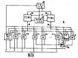
터어빈(10)은 고압(HP)터어빈 구역(20), 중간압력(IP)터어빈 구역(22), 그리고 저압(LP)터어빈 구역(24)를 포함하고 있으며, 이들 모두가 공통 샤프트(28)에 결합되어 주 차단기(34)를 통하여 부하(32)에 전력을 공급하는 발전기(30)을 구동시킨다.The
고압 터어빈구역(20)을 나오는 증기는 보통 재열기(40)에서 재열된 다음 증기 통로에 배치된 하나 혹은 여러개의 정지밸브(SV)와 하나 혹은 여러개의 차단밸브(Ⅳ)를 통하여 중간 압력 터어빈 구역(22)로 공급된다.The steam exiting the high pressure turbine section 20 is usually reheated in the reheater 40 and then intermediate pressure turbine section through one or several stop valves (SV) and one or several shut-off valves (IV) arranged in the steam passage. Supplied to (22).
주차단기(34)가 개방되면, 흡입증기에 의해 발생된 토오크는 회전기어의 터어빈 샤프트(28)을 동기속도로 가속시킨다. 주차단기(34)가 개방되어 있는 한 터어빈은 무부하로 회전하고 속도 제어방식으로 작동한다.When the parking short 34 is opened, the torque generated by the suction steam accelerates the turbine shaft 28 of the rotary gear at a synchronous speed. As long as the parking short 34 is open, the turbine rotates without load and operates in a speed control manner.
일단 샤프트 주파수가 전력시스템 회로망으로 되는 부하(32)의 주파수로 동기화되면, 주차단기(34)는 폐쇄되고 발전기(30)에 의해 전력이 부하로 공급된다. 차단기(34)가 폐쇄된 채로 고압(HP)중간압력(IP) 및 저압(LP)터어빈 구역의 터어빈 회전 조립체로 인해 생긴 주 토오크는 부하(32)로 공급되는 전력의 양을 제어하고, 한편 샤프트 속도는 전력 시스템회로망의 주파수에 의하여 조절된다. 이 상태에서 증기 흡입조절은 보통 부하제어라고 칭하여지며, 이 기간동안 터어빈 속도는 부하(32)에 공급되는 전력을 조절할 목적으로 모니터된다.Once the shaft frequency is synchronized to the frequency of the load 32 which becomes the power system network, the parking short 34 is closed and power is supplied to the load by the generator 30. The main torque generated by the turbine rotating assembly in the high pressure (HP) medium pressure (IP) and low pressure (LP) turbine sections with the
작동중에 터어빈을 제어하기 위하여, 증기 흡입 드로틀 밸브와 조절밸브는 고압 유체 공급원(46)으로 부터 고압유체를 받는 각 밸브 작동회로(44)와 (45)에 의하여 위치가 조절된다. 따라서, 밸브 작동회로(44-1)에서 (44-N)까지는 드로틀밸브(TV1)에서 (TVN)까지를 조절하고 밸브 작동회로(45-1)에서 (45-M)까지는 조절밸브(GV1)에서 (GVM)까지를 조절한다.In order to control the turbine during operation, the steam intake throttle valve and regulating valve are positioned by respective valve actuating circuits 44 and 45 which receive high pressure fluid from the high pressure fluid source 46. Thus, the valve actuation circuits 44-1 to (44-N) regulate the throttle valves TV1 to (TVN) and the valve actuation circuits 45-1 to (45-M) control valves (GV1). Adjust from to (GVM).
위치검출기(47)과 (48)은 밸브와 연결되어 밸브위치를 표시하는 각 피이드 백 신호를 공급한다. 위치검출기(47-1)에서 (47-N)까지가 제각기 드로틀 밸브(TV1)에서 (TVN)까지와 연결되고 위치검출기(48-1)에서 (48-M)까지가 조절 밸브(GV1)에서 (GVM)까지와 제각기 연결된다.The position detectors 47 and 48 are connected to the valves to supply respective feedback signals indicating the valve positions. Position detectors 47-1 to 47-N are connected to throttle valves TV1 to TVN, respectively, and position detectors 48-1 to 48-M are connected to control valves GV1. (GVM) and respectively.
밸브 작동회로의 작동을 위한 제어신호가, 제어목적을 위하여 여러가지 플랜트 요인들의 표시를 이용하는 터어빈 제어시스템(50)으로 부터 유도된다. 이용되는 여러요인들중에는 증기발생 장치(12)와 드로틀밸브들사이의 주 증기통로에 있는 드로틀 압력검출기(52)로 부터 유도된 드로틀 압력의 표시가 이용된다. 고압 터어빈 구역(20)내의 검출기(54)는 임펄스 압력을 표시하고 중간 압력 및 저압터어빈구역(22)와 (24)사이의 교차통로에 있는 검출기(56)은 교차압력을 표시한다. 발전기 출력단에 연결된 전력 검출기(60)은 출력전력을 표시하는 메가왓트(MW)신호를 공급한다. 터어빈 제어시스템(50)에 이용되는 추가입력으로는 실시예에서 3개의 여분의 속도신호를 공급하도록 작동하는 속도검출회로(62)에 의해 얻어지는 속도의 표시가 있다.Control signals for the operation of the valve actuation circuits are derived from the
터어빈 제어시스템(50)은 드로틀 밸브와 조절밸브의 밸브작동 회로를 제어하는 이외에도, 또한 밸브 작동장치(64)와 (65)에 의해 정지 밸브와 차단밸브의 개폐를 제어하도록 작동한다.In addition to controlling the valve actuating circuits of the throttle valve and the regulating valve, the
본 발명의 실시예에 의하면, 플랜트로 출력되는 신호는 물론 플랜트로 부터 터어빈 제어시스템으로 입력되는 선택된 신호들이 신호조절과 파동전압보호를 위하여 현장 말미 회로망(68)에 연결된다.In accordance with an embodiment of the present invention, the signals output to the plant as well as the selected signals input from the plant to the turbine control system are coupled to the field end network 68 for signal conditioning and wave voltage protection.
본 발명의 실시예에 따른 터어빈 제어시스템(50)의 블럭도가 제 2 도에 도시된다. 이 시스템에는 데이타와 작업지시를 포함한 디지탈정보를 저장하기 위한 메모리 장치를 갖는 콘트롤러(70 A)가 포함된다. 디지탈정보를 처리하기 위해 디지탈 처리회로가 마련되며 콘트롤러에는 정보의 입, 출력을 위한 장치가 포함된다.A block diagram of a
이 시스템의 신뢰도는 콘트롤러(70 A)와 동일한 구조를 갖는 제 2 의 콘트롤러(70 B)를 사용하므로써 개선된다.The reliability of this system is improved by using the second controller 70B having the same structure as the controller 70A.
본 발명에서 하드웨어 디지탈 시스템의 복잡성은 시스템을 몇개의 상호 관련된 대등한 기능적 모듀울로 분할하여 각 기능적 모듀울이 그 고유의 기능을 수행하는 처리능력을 갖게 하므로써 간단해진다. 제 2 도에서 기능적 모듀울은 드로틀 밸브와 조절밸브 작동회로를 제각기 제어하기 위한 밸브위치제어회로(74)와 (75)를 포함한다. 따라서 밸브위치 제어회로(74-1)에서 (74-N)까지는 밸브작동회로(44)에서(44-N)까지로 제어신호를 공급하며 드로틀 밸브위치 제어회로를 구성하고, 밸브위치 제어회로(75-1)에서(75-M)까지는 밸브 작동회로(45-1)에서 (45-M)까지를 제어하며 조절밸브제어회로를 구성한다. 이같은 각 제어회로는 디지탈정보를 처리하기 위한 디지탈 처리회로뿐 아니라 데이타와 작업지시를 포함한 디지탈 정보를 저장하기 위한 자체의 메모리 장치를 포함하고 있다.In the present invention, the complexity of a hardware digital system is simplified by dividing the system into several interrelated, equivalent functional modules so that each functional module has the processing power to perform its own function. In FIG. 2 the functional module comprises valve
밸브위치 제어회로(74)와 (75)와 같이 데이타와 작업지시를 포함한 디지탈 정보를 저장하기 위한 자체의 메모리 장치와 이 디지탈 정보를 처리하기 위한 디지탈 처리회로를 포함하는 과속도 보호 콘트롤러(OPC)회로(78)에 의해 속도가 모니터 및 보호된다. OPC회로(78)과 동일하며 신호가 소통되는 OPC 회로(79)의 형태로 과속도 보호의 제 2 채널을 사용하므로써 속도보호 작동의 신뢰성이 더 향상 된다. OPC회로(78)고(79)는 게이트회로(81)을 통하여 조절밸브 위치 제어회로(75)와 직접 상호작용하여 어느 소정의 조건에 따라서 모든 조절밸브를 폐쇄하도록 작동된다. 이폐쇄는 리이드(83)에 인가되는 외부신호에 의하여서도 이루어지는데, 이같은 신호는 예를 들어 게이트(81)에 그리고 밸브위치 제어회로(74-1)에서 (74-N)까지에 공급되는 터어빈 트립 신호 같은 것이다.An overspeed protection controller (OPC) including its own memory device for storing digital information including data and work instructions, such as valve
디지탈 정보는 디지탈 데이타 링크(85, 86)에 의해 밸브위치 제어 및 OPC 회로로부터 콘트롤러(70 A)와 (70 B)모두로 이송 되는 반면에 단지 하나의 선택된 콘트롤러(70 A)또는 (70 B)만이 디지탈 정보를 밸브위치 제어및 OPC 회로로 전송한다. 콘트롤러 선택기(90)은 어느 콘트롤러가 주콘트롤러이고 어느것이 백업 콘트롤러인가를 결정하는 작용을 하며, 또한 디지탈 정보의 하향전송을 위해 데이타 링크(85) 혹은 (86)을 선택적으로 정하는 작용을 한다.Digital information is transferred from the valve position control and OPC circuits to both controllers 70 A and 70 B by digital data links 85 and 86, while only one selected controller 70 A or 70 B Only digital information is sent to the valve position control and OPC circuitry. The controller selector 90 serves to determine which controller is the primary controller and which is the backup controller, and also selectively selects the data link 85 or 86 for downlink transmission of digital information.
터어빈 제어 시스템은 그밖에도 모든 밸브위치 제어 및 OPC회로외에 두 콘트롤러(70 A)(70 B)와 2방 소통하는 (two way communication with)작업자 판넬을 포함한다. 이와같은 결선에 의하여 여러가지 요인들이 작업자에게 전달되게 하여 작업자가 시스템을 직접 수동으로 제어할 수 있다.The turbine control system further includes an operator panel that is in two way communication with both controllers 70 A and 70 B in addition to all valve position control and OPC circuits. This connection allows various factors to be communicated to the operator, allowing the operator to manually control the system.
콘트롤러(70 A)와(70 B)는 구조적으로 동일하며 여러 선행기술의 디지탈 제어회로에 의해 수행되는 바와 같은 종래의 수많은 루우틴을 수행하도록 프로그램 되어져 있다. 예를 들면, 각 콘트롤러는 설정된 셋트 포인트와 변화율에 따르며, 드로틀 압력, 임펄스 압력, 속도 및 메가왓트 값등의 여러피이드 백 신호에 의해 수정된 수요 유량을 선정한다. 콘트롤러는 공지된 밸브 제어 프로그램에 의하여 드로틀 밸브제어, 조절 밸브 단일 밸브제어, 혹은 순차적인 조절밸브 제어방식의 작동에 있어서 수요유량을 만족시키기 위하여 각개의 밸브에 대해 필요한 제어신호를 결정할 수 있다.Controllers 70 A and 70 B are structurally identical and are programmed to perform a number of conventional routines, such as those performed by several prior art digital control circuits. For example, each controller depends on the set point and rate of change, and selects the demand flow rate corrected by various feedback signals such as throttle pressure, impulse pressure, speed, and megawatt values. The controller can determine the control signal required for each valve to satisfy the demand flow rate in the operation of the throttle valve control, the control valve single valve control, or the sequential control valve control method by a known valve control program.
속도제어 및 부하제어 작동중에, 각 콘트롤러는 드로틀 밸브 제어에서 조절밸브제어로 그리고 단일에서 순차적인 조절밸브 제어로 또한 그 역으로 무단 변환을 한다.During speed control and load control operation, each controller performs stepless conversion from throttle valve control to control valve control and from single to sequential control valve control and vice versa.
자체 테스트를 포함한 많은 상이한 테스트 작업을 하는 것이외에도, 콘트롤러는 서로 항상 추적하고 소통하여서 언제나 작업자에 의해 제어가 무단으로 변환되어지게 하거나 혹은 기능 장애의 경우 자동 변환되게한다. 콘트롤러 구조는 다른 콤퓨터 시스템과 소통되도록 확장될 수 있을 뿐만 아니라 현재의 혹은 미래의 제어 또는 테스트 작업을 수용할 수 있도록 쉽게 확장가능하다. 대표적인 콘트롤러(70)이 제 3 도에 도시되어 있다. 콘트롤러(70)의 심장부는 마이크로 콤퓨터(100)로서, 이것은 확장된 마이크로 콤퓨터를 형성하도록 데이타, 어드레스 및 제어버스들에 의해서 많은 다른 장치와 소통한다. 마이크로 콤퓨터(100)는 모토롤러 코오포레이숀에서 상품명 M 68MM 19로 생산되는 구매 가능한 품목으로, 이것은 데이타를 저장하기 위한 마이크로프로세싱 유니트, 입출력(I/O)유니트 및 랜덤 액세스 메모리(RAM)를 갖는 마이크로 콤퓨터이다. 콘트롤러(70)은 또한 예를 들어 상이한 프로그램을 수행하기 위한 여러 작업지시를 저장하기 위해 프로그램 가능한 리드 온리 메모리(PROM=programmable read only memory)를 포함한다. 비록 이 시스템이 더 많은(PROM)을 수용하도록 확장될 수 있지만 제 3 도에는 3개의 이같은 PROM(102)가 도시되어 있다.In addition to doing many different test tasks, including self-tests, the controllers are always tracking and communicating with each other so that control is always changed by the operator or automatically in case of malfunction. The controller architecture can be extended to communicate with other computer systems, as well as easily to accommodate current or future control or test tasks. An
이용될 수 있는 PROM의 한 예는 모토롤라 M 68 MM04-1이 있다.One example of a PROM that can be used is the Motorola M 68 MM04-1.
본 발명의 실시예에서, 작업자 판넬(96)(제 2 도)은 음극선관(CRT)디스플레이 장치를 가질 것이다. 이 디스플레이 포오맷은 콤퓨터 제어 되고 따라서 음극선관을 제어하기 위해 RAM (104)가 특별히 마련된다.In an embodiment of the invention, the operator panel 96 (FIG. 2) will have a cathode ray tube (CRT) display device. This display format is computer controlled and thus
대표적인 비데오 RAM 으로는 매트록스 코오포레이숀(Matrox CORP- ORATION)에서 상품명 EXO-2480으로 생산되는 것이 있다.A typical video RAM is one produced under the trade name EXO-2480 by Matrox CORP-ORATION.
대표적인 터어빈 시스템은 많은 릴레이 작동 접점을 갖는데, 이 접점들의 상태는 어떠한 상태의 도달(혹은 미도달)을 표시한다.예를 들어 이 접점들은 몇개를 들자면 터어빈 래치접점, 부하복귀를 위한 원격 접점 및 회로 차단기 결속 접점등이 있다. 이들 접점의 개폐상태는 콘트롤러로 입력되는 디지탈 1혹은 0신호와 동등하다. 그외에도 작업자 판넬은 디지탈 1혹은 0 입력신호를 또한 공급 하는 여러 푸시버튼을 포함 한다.A typical turbine system has many relay actuation contacts, the status of which indicates the arrival (or not) of any state, for example, these are the turbine latch contacts, remote contacts and circuits for load recovery. There is a breaker binding contact light. The opening and closing states of these contacts are equivalent to the digital 1 or 0 signal input to the controller. In addition, the operator panel includes several pushbuttons that also supply digital 1 or 0 input signals.
콘트롤러는 그 정상 작동중에 어떠한 1혹은 0 신호를 발생하여 과속도, 터어빈 트립, 구동, 전력고장, 자동제어능력 및 많은 경보의 표시에 관련된 접점등과 같은 어떠한 접점을 개방하거나 폐쇄하는 릴레이를 작동시킨다. 따라서, 콘트롤러는 이 디지탈 정보를 입출력시키기 위하여 디지탈 입력회로(106)과 디지탈 출력회로(107)을 포함한다. 이 입출력 기능은 모토롤라 코오포레이숀에서 M 68 MM03으로 생산되는 디지탈 입출력 회로로서 달성되어 진다.The controller generates any one or zero signal during its normal operation to activate a relay that opens or closes any contact such as overspeed, turbine trip, drive, power failure, automatic control capability, and contacts associated with many alarm indications. . Thus, the controller includes a digital input circuit 106 and a
디지탈 입력 신호 이외에도, 콘트롤러는 또한 외부 장비로 부터의 아날로그 입력 신호로서 공급되는 여러가지 트랜스듀우서 및 여러 가지 셋트포인트로 부터의 아날로그 신호 같은 아날로그 입력 신호들을 받는다.In addition to digital input signals, the controller also accepts analog input signals, such as analog signals from various setpoints and various setpoints, supplied as analog input signals from external equipment.
하나 혹은 그 이상의 더 높은 등급의 콤퓨터 콘트롤러를 포함한 확장된 터어빈 제어 시스템에서, 더 높은 등급의 이들 콘트롤러로 아날로그 정보를 출력하는 것이 필요하다. 따라서, 제 3 도의 콘트롤러(70)는 아날로그 정보를 입, 출력 하기 위하여 모토롤라 M 68 MM05 A 같은 아날로그 입력회로와 모토롤라 M 68 MM15CI 같은 아날로그 출력회로를 포함한다.In an extended turbine control system that includes one or more higher class computer controllers, it is necessary to output analog information to these higher class controllers. Accordingly, the
작업자 판넬(96), 밸브위치제어회로(74)와 (75), OPC회로(78)와(79) 및 콘트롤러 선택기(90)같은 제 2 도에 도시된 콘트롤러와 여러 장치들 사이의 디지탈 정보의 전송을 수용하기 위하여, 표시등으로써 일반 목적의 입, 출력(I/O) 회로(120)가 갖추어진다. 전술한 콘트롤러 회로들이 규격에서 벗어난 선반품목인데 반하여, 일반 목적의 입, 출력 회로(120)은 그 기능을 하기 위해 특별히 제조되지만, 이것은 제 4 도의 블럭도에 도시된 바와 같이 규격에 맞는 공지회로로서 제조된다.Of digital information between the controller and the various devices shown in FIG. 2, such as operator panel 96, valve
후술되는 바와 같이, 작업자 판넬은 어떤 정보를 작업자가 입력시키도록 키이보드를 포함한다. 콘트롤러(70)은 어느 키이패드가 눌려졌는가를 알기 위해 주기적으로 키이패드를 스캔하도록 작동한다. 일반목적의 입출력 회로(120)은 작업자가 입력시킨 정보를 받기 위해 작업자 판넬의 키이보드와 연결되는 키이보도 입력회로(122)를 포함한다.As described below, the operator panel includes a keyboard for the operator to input some information. The
작업자 판넬은 또한 콘트롤러로 부터의 디지탈 신호에 의해 포오맷되는 디스플레이를 포함한다. 따라서, 디스플레이출력회로(123)은 디스플레이와 접속되기 위하여 마련된다.The operator panel also includes a display that is formatted by a digital signal from the controller. Thus, the
여러 콤퓨터 시스템은 콤퓨터가 작동한다는 것을 표시하는 출력신호를 공급하기 위한 회로를 포함한다.Many computer systems include circuitry for supplying an output signal that indicates that the computer is operating.
이 신호는 때때로 데드 맨 타이어 신호라고 지칭되며, 회로(124)는 본 발명의 장치에 이 신호를 공급하는 작용을 한다.This signal is sometimes referred to as a dead man tire signal, and circuit 124 acts to supply this signal to the device of the present invention.
디지탈 정보는 트랜시버 장치(125)에 의해 콘트롤러와 밸브 위치제어 및 OPC회로 사이에서 전달되고, 트랜시버 장치의 입력과 출력은 제 2 도에 도시된 디지탈 데이타 링크(85) 혹은 (86)을 구성한다. 회로(122)에서 (125)까지의 독특한 어드레싱과 이들회로로 그리고 이들 회로로 부터의 정보의 전송은 디코우더와 인터페이스 회로(128)에 의해 달성된다. 그밖에, 일반목적의 입, 출력 회로(120)는 데드 맨 타이머(124)의 출력을 조절할 뿐 아니라 표본속도를 조절하기 위하여 그 자체의 실제 시간 클록(129)를 포함한다.Digital information is transmitted between the controller and valve position control and OPC circuitry by the
트랜시버 장치(125)가 제5도에 더 상세히 도시된다. 이 장치에 있어서 데이타는 주 및 여분의 미분선로 구동장치 및 수신기에 의해 콘트롤러와 밸브 위치 제어 및 OPC 회로 사이에 순차로 전송된다. 따라서 제 5 도에서 주 구동장치(132 P)와 여분의 구동장치(132 R)는 어느 구동장치가 마이크로 콤퓨터(100)에 의하여 게이트(138 P)혹은(138 R)에서 인에블링 신호를 공급받는 가에 따라 평형선로(136 P) 혹은(136 R)로 전송하기 위하여 선로(134)에서 동일한 디지탈 입력신호를 수신하도록 배열되어 있다. 한 작동 방식에서, 두 구동장치가 동일한 데이타 신호의 동시 전송을 위해 모두 인에이블될 수 있다.The
트랜시버의 수신기 부분은 제각기 평형선로(142 P)와 (142 R)을 수신하는 주 평형 선로 수신기(140 P)와 여분의 수신기 140 R을 포함한다. 그 수신기들 중에 선택된 하나가 게이트(146 P)혹은 (146 R)에서 마이크로 콤퓨터(100)에 의하여 인에이블링 신호를 어느것이 공급받는 가에 따라 선로(144)에 디지탈 정보를 출력할 것이다.The receiver portion of the transceiver includes a primary balanced line receiver 140 P and an extra receiver 140 R that receive
다시 한번 제 3 도를 보면, 많은 배치에 있어서 콘트롤러 (70)이 다른 더 높은 등급의 콤퓨터 시스템과 소통되는 것이 바람직하다. 이들 다른 시스템들과 콘트롤러(70)사이의 데이타의 유통은 모토롤라 코오포레이숀에서 M 68MM07로 생산되는 직렬 데이타 트랜시버(150)을 구비하므로써 성취된다.Referring again to FIG. 3, in many deployments, it is desirable for the
제 1 도에 도시된 바와 같이 터어빈 제어 시스템(50)(특히 밸브위치 제어 회로(74)와 (75)는 밸브 작동회로(44)와 (45)에 제어 신호를 공급한다. 통상 사용되는 밸브 작동회로의 한 예가 제 6 도에 더 상세히 도시된다.As shown in Fig. 1, the turbine control system 50 (particularly the valve
근본적으로, 드로틀 밸브 혹은 조절 밸브를 표시하는 밸브(152)는 수압피스톤 밸브 작동장치로 되는 밸브서어보모우터(154)에 의해 위치 제어된다. 서어보모우터(154)내에서 피스톤운동은 서어보밸브(156)에 의해 조절되는 수압유체시스템(46)으로 부터의 고압유체의 공급에 의하여 조절된다. 선로(158)의 제어신호는 서어보밸브(156)의 동작을 조절하고, 그 결과 밸브(152)의 위치를 조절한다. 설명을 간결히 하기 위하여, 윤활과 트립회로는 도시되지 않았다.Essentially, the valve 152, which indicates the throttle valve or regulating valve, is position controlled by a
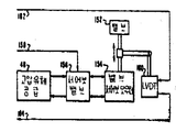
위치 검출기는 선로(162)에서 여자신호를 공급 받아서 공지된 방식으로 밸브위치를 표시하는 피이드백 위치 신호를 선로(164)에 발생하는 선형변수 미분 변압기(LVDT)위치센서(160)의 형태로 된다. 밸브(152)가 드로틀 밸브 이거나 조절밸브이건 간에 그 밸브를 제어하는 대표적인 밸브위치제어회로는 제 7 도에 더 상세히 도시된다.The position detector is in the form of a linear variable differential transformer (LVDT) position sensor 160 which receives an excitation signal from the
각 밸브 위치 제어회로(74) 혹은 (75)는 디지탈 정보를 처리하기 위한 디지탈 처리회로뿐만 아니라 데이타와 작업지시를 포함한 디지탈 정보를 저장하기 위한 메모리장치도 갖는다. 이 메모리 장치는 마이크로 콤퓨터 제어회로(170)내에 내장된다.Each valve
밸브 위치 제어회로(74) 혹은 (75)는 선택된 콘트롤러로 부터 밸브 위치 제어회로로 정보의 전송을 위하여 그리고 주 및 여분의 평형선로(142P)와(142R)을 따라 콘트롤러로 다시 정보를 전송하기 위하여 주 및 여분의 평형선로(136P)와(136R)로 구성되는 디지탈 데이타 링크에 의하여 두 콘트롤러(70A) 및 (70B)와 소통된다. 밸브 위치 제어회로의 트랜시버 장치(171)는 주 및 여분의 구동장치(174P)와(174R)은 물론 주 및 여분의 수신기(172A)와(172B)을 포함한다.케이트(178P)와 (178R)및 (174P)와(R)에 대한 인에이블링 신호는 정보의 상호교환을 위하여 어느 수신기와 어느 구동장치가 작동되는 가를 결정한다.The valve
밸브 위치제어 회로에 대한 다른 입력은 다수의 선로를 구비하는 식별(ID)로(180)로부터 그 각각의 입력이 특정 밸브 위치 회로용 이중 식별을 할 수 있도록 선택적으로 접지될 수 있다.Other inputs to the valve positioning circuit can be selectively grounded from each of the identification (ID) paths 180 with multiple lines so that each input can make a dual identification for a particular valve positioning circuit.
접점 폐쇄 입력 회로(182)는 작업자 판넬의 수동 제어 구역으로 부터 다수의 입력을 받는다. 예로써, 이들 입력들에는 선로(184)의 수동입력, 선로(185)의 상승 입력, 선로(186)의 하강 입력, 선로(187)의 고속입력 및 선로(188)의 신속 폐쇄 입력이 포함된다. 선로(189)의 복귀 입력은 터어빈에 대한 증기 공급이 감소되어야 한다는 것을 표시하는 원격 접점으로부터 나오며, 선로(190)은 클리어 입력을 받는다. 만일 밸브 위치 제어회로가 조절밸브의 제어회로 이면 클리어 신호 입력은OPC회로(78) 혹은(79)중의 하나로 부터 혹은 선로(83)(제 2 도)의 터어빈 트립 접점 신호로 부터 나온다. 만일 밸브 위치 제어회로가 드로틀 밸브의 제어회로이면, 선로(190)의 클리어 신호는 선로(83)(제 2 도)의 터어빈 트립신호이다.The contact closure input circuit 182 receives a number of inputs from the manual control area of the operator panel. By way of example, these inputs include a manual input of
작동중에, 콘트롤러(70A)혹은(70B)중에 선택된 하나는 셋트포인트 입력에 응답하며, 그리고 공지된 밸브조종프로그랩에 따라 각 밸브를 위한 다수의 제어신호를 계산할 것이다. 그 제어신호들은 선정된 코트롤러도 부터 디지탈 데이타 뱅크 밑으로 전달되어서 각 신호는 특별한 확인 번호에 의해 진행되어 특별한 제어신호가 적2절히 확인된 밸브 위치 제어회로에 의해서만 수신된다. 디지탈 형태의 제어신호는 적절히 어드레스된 밸브위치 제어회로에 의해서 받아들어지며 마이크로 콤퓨터 제어회로(170)의 메모리 장치내에 놓여진다. 콤퓨터 프로그램 제어하에서, 제어신호는 디지탈 제어신호가 아날로그 전압으로 변환되어 구동장치(196)으로 공급되는 아날로그-디지탈(A/D)및 디지탈-아날로그(D/A)변환회로(194)로 공급되고, 그 구동장치(196)은 선로(158)의 출력제어신호를 접점(DMT-1)이 폐쇄되어 있는 한 제 6 도의 서어보밸브(156)으로 공급한다.In operation, one of the controllers 70A or 70B responds to the setpoint input and will calculate a number of control signals for each valve in accordance with known valve control programs. The control signals are transmitted from the selected coat roller down to the digital data bank so that each signal is progressed by a special confirmation number and received only by the valve position control circuit where the special control signal is properly identified. The control signal in digital form is received by a properly addressed valve position control circuit and placed in the memory device of the
LVDT 여자회로(198)은 LVDT 위치센서(160)의 적절한 작동을 위해 선로(162)에 출력을 공급하고, 선로(164)의 센서(160)의 피이드백 위치신호는 복조기(200)에 의해 수신된다. 다양한 LVDT 센서들과 작용하기 위해 LVDT 0점 조정회로(202)와 SVDT 이득 조정회로(204)는 후자회로의 출력이 아날로그 밸브 위치 신호를 구성호다록 마련된다. 이 아날로그 밸브 위치신호는, 변환회로(194)로 공급되어 그 신호를 콤퓨터 프로그램제어하에서 콘트롤러로 부터의 제어신호와 비교되고 어떠한 미분오차도 오차를 어떠한 허용범위내로 줄이기 위해 밸브를 어던 한 위치로 구동시키는데 이용되는 디지탈 포오맷으로 변환하기 위해 변환회로(194)로 공급된다.The LVDT excitation circuit 198 supplies an output to the
위치 오차를 0으로 줄이기 위해 제어회로에 기본적으로 적분기능을 제공하는 공지의 비례적인 양의 적분앨고리즘이 사용되는 것이 좋다. 이것은 오차 신호를 취하고 그것에 하기의 제형방정식으로 부터 유도되는 비례신호를 가산하므로써 성취된다.In order to reduce the position error to zero, it is preferable to use a known proportional amount integration algorithm that basically provides an integration function in the control circuit. This is accomplished by taking an error signal and adding to it a proportional signal derived from the formulation equation below.
Y1=H/2T(KE1+KE2)+Y0 Y 1 = H / 2T (KE 1 + KE 2 ) + Y 0
여기서 Y1=신규 계산치Where Y 1 = new calculation
H =표본주기H = sample cycle
T =시간상수T = time constant
K =이득상수K = gain constant
E1=신규 오차신호E 1 = new error signal
E2=구 오차신호E 2 = Old error signal
Y0=최종 계산치Y 0 = final calculation
밸브위치의 디지탈 표시는 구동장치(174P)혹은 (174R)에 의해 (또는 희망시 모두에 의하여)콘트롤러(70A)와(70B)로소통된다. 후술되는 바와 같이, 밸브위치의 아날로그 표시를 측정 판넬 계기에 디스플레이하도록 공급하기 위해 설비가 만들어 진다. 이 목적을 위하여, 계기 구동장치(210)은 이득회로(204)로부터 밸브위치를 나타내는 출력 아날로그 신호를 받으며 이 표시치를 선로(212)에 공급한다. 유사하게, 구동전압을 표시하는 것 또한 바람직하며, 따라서 구동 장치(190)에 대한 아날로그 입력은 또한 계기 구동장치(210)으로 공급되고, 그 출력 신호(21)은 구동전압표시치이다.The digital indication of the valve position is communicated to the
데드맨 타이머 회로(216)은 마이크로 콤퓨터 제어회로(170)이 정확하게 작동할때 그 회로로 부터 입력신호를 주기적으로 받아서 다시 선로(218)에 밸브위치 제어회로의 정상 및 적절한 작동을 표시하는 출력신호를 공급한다. 표시등(120)은 선로(218)과 양의 전압원 사이에 연결되며 데드 맨 타이머(216)가 출력신호를 공급하는 한 오프상태로 남아있는다. 기능장애가 발생하여 선로(218)에 더이상 신호가 공급되지 않으면, 표시등(120)은 전력을 공급받아 기능장애를 표시한다. 그 외에도 데드 맨 타이어 신호가 제거될때, 접점(DMT-1)은 개방되어 그 카아드를 밸브 제어기능으로 부터 효율적으로 제거할 것이다.The
ID(180)을 제외한 지금까지 설명한 제 7 도의 모든 부품들은 용이한 교체를 할 수 D있도록 하나나의 삽입 인쇄 회로카아드위에 놓여질 수 있다. 작업자는 어떤 기능장애등이 커졌는가를 알기위해 단지 다수의 동일한 카아드를 보기만 하면 된다. 이 등이 캐비넷내의 인쇄된 회로 카아드 위에 있지만, 그러나 작업자는 먼저 카아드중에 하나의 고장이 발생하였다는 것을 알기만 하면 된다. 이렇게 하기 위하여 작업자 판넬에는 중앙표시등(222)가 마련되며, 그 한단자는 양의 전압원에 연결되고 나머지 단자는 다이오드(224)같은 다수의 다이오드들의 음극전극에 공통으로 연결되며, 각 다이오드는 별도의 밸브위치 제어회로카아드에 놓인다.All of the components of FIG. 7 described so far except ID 180 may be placed on a single embedded printed circuit card to facilitate easy replacement. The operator only needs to look at the same number of cards to see what kind of dysfunction has grown. While this light is on a printed circuit card in the cabinet, the operator only needs to know first that one of the cards has failed. To do this, the operator panel is provided with a central indicator light 222, one terminal of which is connected to a positive voltage source, the other terminal of which is commonly connected to the cathode electrodes of a plurality of diodes, such as
그러므로 선로(218)의 신호가 기능장애로 인해 제거되어지면, 일일반 목적의 입출력회로인 표시등(120)이 전력 공급을 받을뿐 아니라 작업자 판넬위의 중앙표시등(222)도 전력공급을 받는다.Therefore, when the signal of the
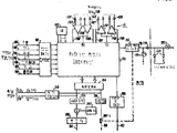
여기 사용되는 대표적인 마이크로 콤퓨터 제어회로(170)가 제 8 도에 또 도시된다. 회로(170)은 클록(clock)회로(231)로 부터 여러 클록입력을 받는 마이크로 프로세서(230)을 포함한다. 메모리 장치(232)는 데이타와 작업지시를 포함한 디지탈 정보를 저장하기 위해 마련되며, 두부분, 즉 RAM(233)과 소거 가능한 PROM (EPROM)(234)로 분할된다. 정보의 입출력은 다수의 입출력 포오트(236)에서(239)까지를 구비하므로써 이루어진다. 포오트들중의 하나, 예를 들어 입출력 포오트(237)은 트랜시버 장치(171)와 디지탈데이타링크에 의한 디지탈 정보의 송수신을 위한 직렬 입, 출력 포오트로 구성된다. 나머지 포오트, 혹은 그 일부분은 변환회로(194)로부터 아날로그 정보를 입력하고 또 변환회로(194)로 디지탈 정보를 출력하기 위해 이용된다. 다른 입력들은 선로(184-190)으로부터의 접점 및 푸시버튼 입력 3들은 물론 ID 입력을 포함한다. 다른 출력들은 트랜시버장치(171)의 제어 인에이블링 신호는 물론 데드 맨 타이며(216)으로 킥킹신호를 포함한다. 마이크로프로세서, 메모리및 입출력 포오트들은 모두 공급된 데이타, 어드레스 및 제어버스들에 의해 데이타, 어드레스 및 제어소통되고 이같은 장치들은 공지의 구매 가능한 표준회로로 구성되거나 그 자체에 제 8 도의 회로를 포함하는 하나의 마이크로콤퓨터 칩으로 구매된다.An exemplary
대표적인 CPROM (234)는 밸브 위치 제어회로의 작동에 필요한 여러가지 루우틴을 포함하기 위해 충분한 용량으로 될 것이다. 예로써 이같은 루우틴에는 트랜시버 장치(171)에 의해 밸브위치 제어회로와 콘트롤러(70A, 70B)사이를 적절히 소통시키기 위해 필요한 것들이 포함된다. 대표적인 머릿글자 루우틴은 어떤 기록기를 구성하고, 기록을 리셋트하며, 그들이 입력인가 혹은 출력인가를 구분하는 입출력 포오트를구성하기 위하여 포함한다. 또한, 특별한 밸브 위치제어 회로의 확인은 메모리에 판독된다. 또한 예를 들어 1/8초마다 주기적으로 여러 접점과 푸시버튼입력을 스켄 즉, 주사하게 하고, 하나 혹은 여러 신호가 있을때 필요한 응답을 하기 위하여 루우틴이 포함될 것이다. 이같은 응답은 메모리장치에 저장된 제어 신호를 새로운 것으로 하나 혹은 그 이상의 미리 설정된 속도로 바꿀 수 있고 새로 계산된 위치신호를 콘트롤러(70 A)와(70 B)로 다시 전송한다. 작업지시에는 또한 밸브 구동신호를 결정하기 위해 양의 비례하는 적분 엘고리즘이 포함될 것이다. 예를 들어 접점, 주사, 계산등의 이들 여러 루우틴들이 널리 이용되고 이 분야에 숙련된 자에게 공지되어 있다.
대표적인 OPC회로 (78) 혹은 (79)가 제9도에 도시된다. 일반적으로, 그리고 이 경우에, OPC회로의 기능은 터어빈 속도를 표시하고, 그 속도가 이 시스템의 정격속도보다 미리 설정된 양만큼, 예를 들어 103%초과하면 어떤 밸브의 폐쇄를 시작하고, 그 속도가 만일 예를 들어 110%같은 제 2 의 미리 설정된 양만큼 정격속도를 초과하면 전 시스템이 폐쇄도어야 한다는 것을 표시하는 트립신호를 개시하는 것이다.A representative OPC circuit 78 or 79 is shown in FIG. In general, and in this case, the function of the OPC circuit indicates the turbine speed, and if the speed exceeds the rated speed of this system by a preset amount, e.g. 103%, the valve starts to close and the speed Is to initiate a trip signal indicating that the entire system should be closed if, for example, the rated speed is exceeded by a second preset amount, such as 110%.
OPC회로(78)이나(79)는 또한 신속히 밸브를 조절하는 작용을 한다. 기본적으로, 만일 터어빈 부하가 발전기 출력을 미리 설정된 값만큼 초과하면, 그리고 트랜스듀우서에 고장이 없다면, 차단 밸브들은 일정한 시간지연후에 폐쇄되고 또 재개된다. 이같은 작용은 신속한 밸브조절이라고 불려지며, 고장상태를 감지한후에 신속하게 터어빈 입력동력을 감소시키는 방법이다.OPC circuit 78 or 79 also serves to quickly adjust the valve. Basically, if the turbine load exceeds the generator output by a preset value, and there is no fault in the transducer, the shutoff valves close and resume after a certain time delay. This action is called rapid valve regulation and is a way to quickly reduce the turbine input power after detecting a fault condition.
OPC회로는 어떠한 속도 입력에서 작동하여 제어목적으로 속도신호 RPM 을 유도해낸다. 제10도를 또 참조하면, 속도 입력은 터어빈 샤프트(28)에 부착된 노치형 휘일(254)에 근접되어 있는 다수의 속도변환가(250, 251) 및 (252)로부터 유도된다. 변환기(250-252)는 휘일의 동작에 응답하는 대략 사인파로되는 출력파형을 발생하기 위하여 휘일(254)로 부터 미리 설정된 거리에 놓이며 그 사인파의 주파수는 터어빈속도에 비례한다.The OPC circuit operates on any speed input to derive the speed signal RPM for control purposes. Referring again to FIG. 10, the speed input is derived from a number of
감시계기처리회로(256)은 변환기(251)의 출력신호에 응답하여 선로(258)에 터어빈 속도를 표시하는 아날로그 신호를 공급한다. 감시계기 회로와 관견된 3개의 속도변환기의 이용은 공지되어 있으며 예를들어 미합중국 특허 제4,71,897호와 제4,35,624호에 설명되어 있다.The monitoring instrument processing circuit 256 supplies an analog signal indicating the turbine speed to the
이 장치에서 변환기(250)으로 부터의 출력은 선로(260)에서 OPC회로(78)로 공급되며, 이 회로는 그에 응답하여 선로(261)에 채널 1 RPM 출력 신호를 구성하는 출력 RPM 신호를 공급할 것이다. 유사하게, 변환기(252)로부터의 출력은 선로(262)로 OPC회로(9)에 공급되고, 이 회로는 그에 응답하여 선로(263)로 채널 2 RPM 출력 신호를 구성하는 출력 RPM 신호를 공급한다.In this device, the output from
OPC 회들은 또한 제어목적으로 콘트롤러(70 A)와 (70 B)에 전송하기 위해 정확한 추정 RPM 신호를 발생하는 작용을 한다. 이 유효한 추정 RPM 신호를 발생하기 위하여, 각 OPC회로는 3개의 속도 입력 신호를 받는데, 첫번째는 선로(258)의 감시 신호, 두번째는 선로(260) 혹은(262)의 각각의 속도입력, 그리고 세번재는 다른 OPC 회로로 부터의 RPM 신호이다. 즉, 선로(261)의 RPM 신호는 OPC회로(79)로 공급되고 선로(263)의 RPM 신호는 RPC회로(78)로 공급된다.OPC cycles also serve to generate accurate estimated RPM signals for transmission to controllers 70 A and 70 B for control purposes. To generate this valid estimated RPM signal, each OPC circuit receives three speed input signals, the first being a monitoring signal on
제 9 도를 다시한번 참조하면, 대표적인 OPC회로에는 제 8 도의 마이크로 콤퓨터 제어회로(170)과 물리적으로 동일한 마이크로콤퓨터 제어회로(270)가 포함되며 OPC 및 신속한 밸브 조절 작용을 위해 그 자체 프로그램이외에도 몇개의 프로그램이 포함된다.Referring again to FIG. 9, a representative OPC circuit includes a
제 7 도의 트랜시버 장치(171)과 동일한 트랜시버 장치(271)은 OPC 회로와 콘트롤러(70 A, 70 B)사이의 디지탈 정보의 연계를 위해 마련된다. 제 2 도에 도시된 바와같이, OPC 회로는 밸브위치 제어회로와 동일한 정보를 받으므로, ID 회로(273)가 OPC 회로와 선택적인 어드레싱이 달성될 수 있도록 마련된다.The same transceiver device 271 as the transceiver device 171 of FIG. 7 is provided for linkage of digital information between the OPC circuit and the controllers 70A and 70B. As shown in Fig. 2, since the OPC circuit receives the same information as the valve position control circuit, the ID circuit 273 is provided so that selective addressing with the OPC circuit can be achieved.
속도 변환기로부터의 거의 정현파인 속도 입력 신호는 계수기회로(276)로 계수되는 사각파형으로 변환되고, 이 계수기의 출력은 콤퓨터 프로그램에 의해 작동되어 RPM 신호를 유도한다. 계수로부터 지극히 정확한 RPM 신호를 유도하기 위하여, 미합중국 특허 제4,99,237호에 설명된 바와 같은 공지의 디지탈 필터링 앨고리즘이 사용된다. 계산된 디지탈 신호는 변환회로(278)에 의하여 작용되며, 여기서 아날로그 신호로 변환되고 계기 구동장치(280)으로 공급되고, 이것의 RPM 출력신호는 작업자판넬, 측정판넬 그리고 다른 OPC 회로의 속도입력으로 공급된다.The almost sinusoidal speed input signal from the speed converter is converted into a square wave that is counted by the counter circuit 276, and the output of the counter is operated by a computer program to induce an RPM signal. In order to derive an extremely accurate RPM signal from the coefficients, a known digital filtering algorithm as described in US Pat. No. 4,99,237 is used. The calculated digital signal is acted on by the conversion circuit 278, where it is converted into an analog signal and fed to the
OPC 회로는 그 신속한 밸브조절작용중에 변환기(56)(제 1 도)에서 압력신호를 받을 뿐만 아니라 전력 검출기(60)으로 부터의 메가와트, 즉, MW 신호를 받는다. 이 신호들은 연산 증폭기(282)와(283)에 의해 증폭되고 조절되며, 그 증폭기의 출력은 비교기 회로(284)로 공급된다. 조절된 MW 및 압력신호가 데드 밴드 조정(286)에 의해 결정된 바와 같은 미리 설정된 양만큼 차이가 있으며 비교기(284)는 마이크로 콤퓨터 제어회로(270)로 신속한 밸브 조정작용이 개시 되어야 한다는 것을 표시하는 출력신호를 공급할 것이다.The OPC circuit receives not only a pressure signal from the transducer 56 (FIG. 1) but also a megawatt, i.e., MW, signal from the power detector 60 during its quick valve adjustment action. These signals are amplified and regulated by
연산 증폭기(282)로 부터의 MW 신호는 작업자 판넬과 측정판넬에 표시되도록 계기구동장치(280)로 공급된다. 그밖에, 그 신호는 연산증폭기(283)과 함께 입력신호가 마이크로 콤퓨터 제어회로(270)에 의해 사용될 디지탈 포오맷으로 변환 되는 변환회로(278)로 공급된다. MW 신호는 저장소로 보내지고 그 다음에 트랜시버 장치(271)에 의해 콘트롤러(70 A)와 (70 B)로 전송되도록 그것으로부터 판독된다.The MW signal from the operational amplifier 282 is supplied to the
접점 폐쇄 입력회로(290)은 선로(291)의 OPC 시험, 선로(292)의 디스에이블, 선로(293)의 신속한 밸브조절, 선로(294)의 신속한 밸브억제, 선로(293)의 신속한 밸브조절, 선로(294)의 신속한 밸브억제, 선로(295)의 차단기 및 선로(296)의 자동정지 래치같은 다수의 외부 발생신호를 마이크로 콤퓨터 제어회로(270)로 입력한다.The contact closure input circuit 290 allows for OPC testing of the track 291, disabling the track 292, quickly adjusting the valve of the track 293, quickly suppressing the valve of the track 294, and quickly adjusting the valve of the track 293. A plurality of externally generated signals, such as rapid valve suppression of the line 294, breakers of the line 295 and automatic stop latches of the
접점 폐쇄 출력회로(300)은 선로(301)에 클리어 신호, 선로(302)에 차단 밸브 개량신호, 선로(303)에 차단밸브 폐쇄신호, 그리고 선로(304)에 트립신호를 출력한다.The contact
속도제어 작용중에, 선로(258)의 감시 속도신호와 다른 OPC회로로부터의 속도 입력은 다지탈 신호로 변환되고, 계수기 회로 (276)의 출력단으로 부터 유도된 RPM 신호 이외에도 이 두 신호들이 저장된 프로그램에 의해 비교되어 트랜시버장치(211)을 통하여 콘트롤러(70 A)와 (70 B)로 전송되는 정확한 추정 RPM 신호를 발생하는 마이크로 콤퓨터 제어회로로 공급된다. 또 하나의 프로그램에 의하여 계산된 RPM 값은 정격속도의 103%를 표시하는 저장치와 비교되고, 만일 계산치가 이 저장된 103% 값을 초과하면, 콤퓨터는 클리어 선로(301)에 출력을 일으킨다. 제 2 도를 다시보면, OPC(78)혹은 OPC(79)로부터의 클리어 신호가 게이트 회로(81)을 통하여 모든 조절밸브 위치제어회로(75-1)에서(75-M)까지로 인가 된다. 이 클리어 입력신호는 제 7 도의 선로(190)에 나타난다. 만일 과속도 상태가 지속되면, 계산속도치는 결국 정격속의 110%인 저장치와 비교되고 또 초과하면 콤퓨터는 선로(304)에 트립상태를 표시하는 출력을 일으킨다. 이 출력은 터어빈 시스템을 정지시키거나 혹은 대신에 작업자에게 트립상황이 존재한다는 것을 표시하는 가청 혹은 가시신호를 보낸다.During the speed control operation, the monitoring speed signal of the
또 하나의 콤퓨터 작동에 있어서, 비교기(284)의 출력은 신호의 존재여부를 알리기 위해 주기적드로 검사되고, 만일 존재하면 신로(303)에 출력신호를 공급하므로써 신속한 밸브 조절 작용이 개시되어 차단 밸브를 폐쇄할 것이다. 일단 차단 밸브들이 폐쇄되면 그들은 재열기내에 압력의 형성을 감소시키기 위해 가능하면 빨리 다시 열린다. 차단밸브를 재개하는 신호는 폐쇄신호가 공급된 후 수분의 일초내에 보통 선로(302)로 공급된다.In another computer operation, the output of the comparator 284 is periodically checked to indicate the presence of a signal, and if present, a quick valve adjustment action is initiated by supplying an output signal to the furnace 303 to shut off the shutoff valve. Will shut down. Once the shutoff valves are closed they reopen as soon as possible to reduce the build up of pressure in the reheater. The signal for restarting the shutoff valve is normally supplied to the track 302 within one second of a few minutes after the closing signal is supplied.
마이크로콤퓨터 제어회로(270)가 고장인 경우, 이 장치는 선로(301)에서 (304)까지에 어떠한 출력신호도 나타나는 것을 방지한다. 이것은 선로(306)의 신호에 의해 접점 폐쇄출력회로(300)을 디스에이블하는 작용을 하는 데드맨 타이며(305)를 제공하므로써 성취된다.If the
제 7 도에 관하여 설명된 것과 유사한 방식으로, 제 9 도의 회로는 데드 맨 타이머(305)가 출력신호를 공급하는 한 작동되지 않을 고장표시등(307)을 포함하는 하나의 인쇄회로기판에 내장된다. 데드 맨 타이머(305)는 또한 다이오드(306)을 통하여 양전압원에 연결되고 고장표시에 의해 작동되는 중앙표시등(310)에 연결된다.In a manner similar to that described with respect to FIG. 7, the circuit of FIG. 9 is embedded in a single printed circuit board including a
선로(291)과(292)로 부터의 OPC 시험 및 디스에블 입력 신호들은 시험목적으로 작업자 제어반으로 부터 나오며 나머지 입력 신호들은 사용자 발전 장비로 부터 나온다. 신속한 밸브 조절입력은 시험목적으로 사용되는 반면에 신속한 밸브 조절 억제 입력은 MW 및 교차압력이 맞지 않을때에도 어떤 차단밸브의 폐쇄도 방지한다. 차단기 선로의 신호는 발전기 회로 차단기가 폐쇄되었음을 표시하고 정지 래치선로의 신호는 터이빈 래치 접점들이 닫히고 터어빈이 작동된다는 것을 표시한다.OPC test and disable input signals from lines 291 and 292 are from the operator control panel for testing purposes and the rest of the input signals are from user-generated equipment. Rapid valve control inputs are used for testing purposes, while rapid valve control suppression inputs prevent closure of any shutoff valves even when the MW and cross pressure are not met. A signal on the breaker line indicates that the generator circuit breaker is closed and a signal on the stop latch line indicates that the turbine latch contacts are closed and the turbine is activated.
제11도는 또한 콘트롤러(70 A, 70 B)와 밸브 위치 제어 및 OPC 회로 간의 직렬 데이타 통신을 허용하는 디지탈 데이타링크(85)와(86)을 도시한다. 한 실시예에서, 단 하나의 콘트롤러가 선정되어 선정된 밸브위치제어 및 OPC 회로에 의해 사용될 제어신호를 발생하고 데이타 링크(71)을 따라 이 정보를 선정되지 않은 콘트롤러와 소통하게 한다. 따라서, 한 셋트의 접점(320) 혹은 (321)이 하향데이타 링크를 위해 코트롤러선택기(90)에 의해 폐쇄된다. 밸브위치 제어 및 OPC 회로중의 각기 하나에 의한 데이타전송은 콘트롤러(70 A)와 (70 B)에 동시에 공급되고, 따라서 상향 데이타 링크에는 점점이 필요하지 않는다.FIG. 11 also shows digital data links 85 and 86 that allow serial data communication between controllers 70 A and 70 B and valve position control and OPC circuitry. In one embodiment, only one controller is selected to generate a control signal for use by the selected valve position control and OPC circuitry and to communicate this information with the unselected controller along the
그리하여, 제11도는 밸브 위치 제어 및 OPC 회로들이 모두 함게 1군의 선로구조로 버스되고 통신 원안은 확인, 데이타 유통 및 데이타 안전에 관해 ANSI (미합중국 공업규격)×3.28…1976표준에 따르는 것이 좋다. 상하 평형 선로들은 완전히 여분의 것이며 양호한 실시양태에서 선정된 콘트롤러로부터의 전송은 주 및 여분의 선로 모두에서 이루어지고, 한편 특별히 어드레스된 밸브위치 제어 혹은 OPC 회로는 수신하는 단 하나의 평형 선로를 선정한다. 보통, 주 버스는 데이타가 규정된 기간동안 수신된 한은 선정 되고, 이 경우 여분의 버스기 선정될 것이다.Thus, Figure 11 shows the valve position control and OPC circuits all bused together in a group of track structures, and the communication protocol is ANSI (US) standards for identification, data distribution and data safety. It is recommended to comply with the 1976 standard. The up and down balanced lines are completely redundant and in the preferred embodiment the transmission from the selected controller is made on both the main and redundant lines, while the specially addressed valve position control or OPC circuit selects only one balanced line to receive. . Normally, the main bus will be selected as long as data is received for the specified period, in which case an extra bus will be selected.
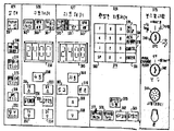
제12도는 작업을 용이하게 하도록 상당히 단순화되고 최소의 공간에서 증가된 작업성능을 갖도록 기능적으로 배치된 작업자 판넬(96)의 추가도면이다.12 is a further view of the operator panel 96 which is considerably simplified to facilitate the work and is functionally arranged to have increased work performance in a minimal space.
이 작업자 판넬은 다수의 기능적 모듀울 혹은 구역으로 분할되고, 이 구역은 상태구역(324), 보수 및 시험구역(325), 그리고 수동제어구역(326)에 마련된 3레벨의 제어, 자동제어구역(327), 작업자의 콘트롤러(70 A) 및 (70 B)와의 여러 상호작용을 위해 CRT(330)과 관련작동되는 확장된 자동 제어구역(328)을 포함한다.This operator panel is divided into a number of functional modules or zones, which are three levels of control, automatic control zones provided in the
구역(324)에서(328)까지의 판넬의 상세한 것은 제13도에 다시 도시된다. 상태구역(324)는 다수의 표시등(222, 310) 및 (334)에서 (337)까지를 포함한다. 제 7 도에 미리 도시된 표시등(222)는 밸브위치 제어회로중의 어느 하나 로도 기능장애가 생기면 작동된다. 제 9 도에 이미 도시된 표시등(310)(제13도에는 OPC 모니터로 표시)은 2개의 OPC 회로 중의 어느 하나라도 기능장애가 생기면 작동된다. 유사한 기능장애 장치가 콘트롤러(70 A)와 (70 B)를 위해 마련되고 표시등 (347)와(335)(제13도에는 각각 코트롤러 A모니터, B모니터로 표시)는 콘트롤러들중의어느 하나의 고장도 제각기 표시하기 위해 마련된다. 여러 회로들에 전력을 공급하기 위하여 다수의 직류전원이 마련되여, 표시등(336)(제13도에는 DC 포 표시)은 그 전원중의 어느하나라도 고장나는 것을 표시하기 위해 마련된다. 상태구역의 마지막 표시등은 터어빈이 트립되면 작동되는 표시등 (337)(제13도에는 터어빈 트립으로 도시)이다. 이표시등들은 광우너의 작동상태가 결정되도록 눌러서 시험할 수 있는 특성을 갖는 형태로 되는 것이 좋다.Details of the panels from
보수 및 시험구역(325)는 어떤 OPC 회로 작동을 제어하기 위하여 키이 작동스위치(340)을 포함한다. 도시된 수직위치에 대해, 2개의 OPC 회로는 서어비스될 것이다. OPC 회로(78)은 키이 스위치를 시험채널 1(TEST CHAN 1)로 표시된 위치로 회전시켜서 작동되고, OPC 회로 (79)는 키이 스위치를 시험채널 2(TEST CHAM 2)로 표시된 위치로 회전시켜서 작동된다. 기계적 과속도 시험을 할 수 있도록 어느 OPC 회로도 작동되지 않을 예정이며, 키이 스우치(40)은 디스에이블드(DISABLED)라고 표시된 위치로 동작된다. OPC 회로에 대한 OPC TEST 와 OPC DISABLE 입력은 제 9 도에 선로(291)과 (292)의 제 1 도의 두입력으로 도시 된다. 제어 시스템의 작동에 있어서, 마이크로 콤퓨터 메모리 장치에는 여러 요인들, 예를들어 규정 리셋트시간, 경보한계, 피이드백 루우프의 이득등의 요인 즉, 파라미터가 이용된다. 정상작동 상태에서, 일단 이들 파라미터들이 결정되면, 이들은 작업자에 의해 변경될 수 없다. 그러나 보수 및 시험구역(325)는 이런 변경을 위한 설비가 되어 있다. 이것은 파라미터의 변경이허용된다는 것을 표시하는(PARA CHAMFE PERM)로 표시된 위치로 이동되는 키이 작동 스위치(342)와 관련하여 이루어진다.The maintenance and
제어 시스템이 비직렬되엇을 때, 이것은 작업자 훈련을 위해 이용될 수 있다. 이같은 경우, 키이 스위치(342)는 시뮬레이션(STMULATION)으로 표시된 위치로 이동되고, 여러 모의 시스템 신호가 코넥터(344)를 통하여 공급된다.When the control system is deserialized, it can be used for worker training. In such a case, the
수동 백업 제어는 눌려질 대 수동 백업 방식의 작동으로 돌입되는 수동 푸시버튼(350)을 포함하는 구역(326)에 의하여 공급된다. 수동방식의 작동중일 때, 드로틀 밸브들은 푸시버튼(353)과 (354)에 의해 상승 또는 하강된다. 이들 밸브들의 상승과 하강은 예를 들어 매분 5%같은 소정의 속도로 된다. 예를 들어 매분 331/3%같은 보다 신속한 소정의 속도는 급속작용(FAST ACTION) 푸시 버튼(355)을 또 작동시키므로써 이루어진다. 비상 사태에 대비하여 밸브를 예를 들어 매분 2%의 속도와 같이 급속히 닫는 것이 바람직하고, 급속폐쇄(rapid close)푸시버튼(356)은 이 목적으로이용된다. 이 장치에 잇어서 푸시버튼(35)에서(356)까지의 작동에 의하여 공급되는 신호들은 선행기술의 제어시스템에서 이용되는 어떠한 추적 혹은 제어회로도 개재되지 않고 직접 밸브 위치 제어 회로로 들어간다는 것에 유의 해야 한다. 제 9 도의 opc 호리의 계기 구동장치(280)으로 부터의 MW 혹은 RPM신호들은 수동 제어 구역 (326)의 계기(358)에 선택적으로 표시된다. 이 계기는 다중편 발광 다이오드(LED) 디스플레이 형태로 된다. RPM 혹은 MW 신호의 선택적인 표시는 스플릿-렌즈, 후광, 교호 작동되는 푸시버튼(360)에 의해 결정된다. OPC 호로(78) 혹은 (79)로 부터의 MW 및 RPM 신호의 표시는 역시 스플릿-렌즈, 후광, 교호 작동되는 채널 1, 2(361)을 구비하여 이루어진다.Manual backup control is supplied by a
터어빈 래치(TURBINE LATCH)푸시버튼(362)가 수동 제어구역(326)에 마련되어 터어빈 수압 시스템으로 접점을 폐소해시켜 수압 작동 압력의 형성이 시작된다.A
자동 제어 구역(327)의 자동(AUTO)푸시버튼(364)는 이 장치를 콘트롤러 메모리에 저장된 MW 혹은 RPM 셋트 포인트가 작업자에 의해 변경되는 제 1 자동 제어방식으로 놓는다.The AUTO pushbutton 364 of the
만일 회로 차단기(34)(제 1 도)가 개방되면 터어빈은 전기부하 없이 회전되고 속도 제어 방식으로 작동된다. 이같은 방식일때, LED 변형인 계기(365)는 RPM 셋트 포인트를 표시할 것이다. 회로 차단기가 닫히면, 이 시스템은 부하 제어방식으로 작동되고 셋트 포인트는 계기(365)에 의하여 표시될 것이다.If the circuit breaker 34 (FIG. 1) is opened, the turbine is rotated without electrical load and operated in a speed controlled manner. In this way, the LED variant,
스플릿-렌즈 표시등(366)은 2개의 셋트 포인트중 어느 것이 표시되는 가를 표시할 것이다.Split-lens indicator 366 will indicate which of the two set points is to be displayed.
셋트 포인트를 변경하기 위해, 작업자는 푸시버튼(368) 혹은 (369)와 관련된 요구 푸시버튼(367)을 작동시키고, 전자는 셋트 포인트 값을 증가시키는데 이용되며 후자는 감소시키는데 이용된다. 셋트 포인트가 변화되는 속도, 즉 RPM/분 혹은 MW/분은 푸시버튼(368)이나 (369)와 관련된 분속(RATE PER MINUTE) 푸시버튼(370)을 작동시켜서 변화된다.To change the set point, the operator activates the
자동 제어구역(327)은 2개의 다른 스플릿-렌즈 후광 푸시버튼을 포함하는데, 그중 하나인 푸시버튼(370)은 이 장치를 드로틀 밸브 제어 혹은 조절밸브 제어방식의 작동으로 놓기 위한 것이다. 일반적으로, 기동시와 거의 정격속도의 2/3까지 작업자는 드로틀 밸브 제어방식을 선정할 것이며 일단 정격속도의 2/3 혹은 어느 다른 미리 설정된 비율의 정격속도가 얻어지면, 작업자는 조절밸브 제어방식의 작동으로 전환할 것이다.
나머지 푸시버튼(371)은 작업자가 장치를 전 아아크 흡입과 동등한 단일 조절밸브 방식의 작동이나, 혹은 부분적인 아아크 흡입과 동등한 순차적인 조절밸브 방식의 작동으로 놓을 수 있게 한다.The remaining pushbuttons 371 allow the operator to place the device in actuation of a single regulating valve equivalent to full arc suction, or in sequential actuation valve equivalent of partial arc suction.
자동 제어방식의 성능은 확장된 자동 제어구역(328)의 키이보드(374)를 구비하므로써 상당히 향상되고, 키이보드는 CRT(330)과 관련하여 수치셋트 포인트의 입력과 표시, 피이드백 루우프와 제한기 상태의 표시 및 작업자와의 상호작용을 위한 대화를 허용한다. 이 확장된 자동 제어방식의 작동은 확장된 자동(EXP AUTO) 푸시버튼(375)를 작동시켜서 개시된다.The performance of the automatic control method is significantly improved by having the keyboard 374 of the extended
SEL DISP 푸시버튼(376)으로 작업자는 CRT 상에 번호에 의하여 선택되는 여러가지 특성의 리스트를 놓을 수 있다.The
설명만을 하기 위하여, 이들 특성들에는 몇가지 들자면, MW와 RPM 같은 요구를 포함한 여러 파라미터의 셋팅, MW/분 RPM/분 같은 속도, 그리고 밸브위치, 부하의 고저한계, 원격 셋트 포인트 드로틀 압력한계, 프로그램된 셋트 포인트 드로틀 압력한계 같은 여러가지 한계를 포함한다.To illustrate, these characteristics include, among others, setting of several parameters including requirements such as MW and RPM, speeds such as MW / minute RPM / minute, valve position, low limit of load, remote set point throttle pressure limit, and programming. Includes several limitations such as set point throttle pressure limits.
제어 특성중의 하나는 정상적으로는 변화될 수 없지만 키이 스위치(342)를 파라미터 변화 허용되는 어떤 파라미터를 변경하는 설비가 구비되는 것이다.One of the control characteristics is that there is a facility to change any parameter that is normally not changeable but that allows the
안전특성으로서, 선택중의 하나는 밸브 시험을 위한 것이다. 밸브 시험의 이 선택과 관련하여, 밸브 시험폐쇄(VALVE TEST CLOSE) 푸시버튼(377)은 밸브를 닫기 위해 작동된다. 한 장치에 있어서, 그 선정된 밸브가 드로틀 밸브, 재열정지 혹은 차단 밸브이면, 선정된 밸브는 작업자가 밸브 시험 폐쇄 푸시버튼(377)을 놓을 때 다시 열린다. 반면에 조절밸브가 시험되고 밸브 시험 폐쇄 푸시버튼(377)이 작동되면, 조절밸브는 밸브 시험 개방(VALVE TEST OPEN) 푸시버튼(378)이 작동되어 그 밸브를 시험전 위치로 복귀할 때까지 닫혀진 상태로 남아 있는다.As a safety feature, one of the options is for valve testing. In connection with this selection of valve tests, the VALVE TEST CLOSE pushbutton 377 is activated to close the valve. In one device, if the selected valve is a throttle valve, re-stop or shut-off valve, the selected valve is opened again when the operator releases the valve test close pushbutton 377. On the other hand, when the control valve is tested and the valve test close pushbutton 377 is activated, the control valve is closed until the VALVE TEST OPEN pushbutton 378 is activated to return the valve to its pre-test position. Remain in state.
수치 입력 이외에도, 키이 보드(374)는 작업자와의 상호 작용을 위한 다수의 푸시버튼을 포함한다. 그리하여 만일 어떤 표시가 선정되면, 작업자는 그것을 취소하고 CANCEL 푸시버튼(379)를 작동시켜서 새로운 것을 선정한다. 이 푸시버튼은 또한 작업자 입력 데이타를 취소하기 위해 사용되기도 한다.In addition to numerical input, the key board 374 includes a number of pushbuttons for interaction with the operator. Thus, if an indication is selected, the operator cancels it and activates the CANCEL
수치 데이타의 입력과 관련하여, SP 푸시버튼(380)은 작업자가 입력시킨 것을 증명하기 위해 이용된다.In connection with the entry of numerical data, the
즉, 일단 수치 입력이 만들어지면, 그리고 작업자가 푸시버튼(380)을 작동시키면, CRT 표시장치는 작업자가 선정한 번호를 표시한다. 그 다음 작업자는 ENTER 푸시버튼(381)을 작동시켜서 데이타가 시스템 안으로 들어가게 한다. 이 푸시버튼은 또한 확장된 자동제어 방식의 작동중에 CRT에 발생된 문제의 확인을 위해 이용되어도 된다.That is, once the numerical input is made and the operator operates the
요구정지(DEMAND HOLD) 푸시버튼(382)와 요구동작(DEMAND GO) 푸시버튼(383)은 확장된 자동제어 방식일 때 항상 작용한다. 이들은 요구 셋트 포인트의 이동을 중지시키고 그 이동을 중지후에 지속시키는데 사용된다.The
확장된 자동 제어구역(328)의 작동에는 CRT상의 여러 경고 혹은 경보를 발광시키기 위한 설비를 포함하여서 작업자가 적절한 행동을 취할 수 있다. 이들 경보는 작업자에 의해 푸시버튼(384)를 작동시켜서 확인될 수 있으며, 이것은 다시 발광 경보 상태를 취소한다.Operation of the extended
따라서, 작업자 판텔은 3개의 다른 레벨의 작동, 즉 수동제어, 자동제어 그리고 확장된 자동제어를 제공한다. 이들 3개의 별도의 기능은 3개의 다른 판넬구역(326, 327, 328)에 의해 수행되고, 각 구역은 관련된 푸시버튼 제어소자들과 어떤 형태의 표시장치를 포함한다. 이 장치로써 판넬구역의 어느 하나라도 기본적인 제어를 중단하지 않고 서어비스될 수 있으며, 이것은 하나의 자동제어 방식이 이같은 서어비스 작동중에 혹은 고장의 경우에 나머지 하나의 작업장치로서 사용될 수 있으므로, 자동 제어구역중의 어느 하나의 서어비스를 포함한다.Thus, the operator pantel offers three different levels of operation: manual control, automatic control and extended automatic control. These three separate functions are performed by three
터어빈 제어 시스템의 작동중에 시스템 전체의 여러가지 전압을 검사하는 것이 바람직하다. 이 목적을 위하여 제14도에 도시된 보정 판텔(390)이 마련된다. 전압 점검은 콘트롤러(70A)가 직결되어 있고(70B)가 대기상태일 때 혹은 그 역으로 되어 있는 동안 수행된다. 따라서, 스플릿-렌즈 후광 교대 작용 푸시버튼(392)가 콘트롤러(70A)를 직결하기 위해 마련되어 있는데 반해 푸시버튼(393)은 콘트롤러(70B)를 직결하기 위해 마련된다.During the operation of the turbine control system it is desirable to check the various voltages throughout the system. For this purpose a correction pantel 390 as shown in FIG. 14 is provided. The voltage check is performed while the controller 70A is directly connected (70B) and in the standby state or vice versa. Thus, a split-lens
최소 공간내에서 점검 작용을 하기 위해, 보정 판넬은 다수의 표시 선택 다이알(397, 398, 399)와 함께 하나의 계기 표시장치(395)를 포함한다. 다이알(397)에 관한한, 각 콘트롤러는 +5볼트, +12볼트 전원을 갖는다. 콘트롤러(70A) 나 (70B)에 사용되는 이들 세 전압들중의 어느 하나는 지침(400)을 원하는 파라미터표시로 적절히 동작시키므로써 계기(395)에 표시된다.To act as a check in the minimum space, the calibration panel comprises one instrument display 395 with a number of display selection dials 397, 398 and 399. As far as dial 397 is concerned, each controller has a +5 volt and a +12 volt power source. One of these three voltages used in controller 70A or 70B is displayed on instrument 395 by appropriately operating instruction 400 with the desired parameter display.
작업자 판넬과 어떤 접점 입력은 물론 밸브위치 제어회로는 +24와 +48 볼트의 전원을 필요로 한다. 이들 전원들은 또한 백업장치가 마련되고 지침(400)은 계기(395)에 표시하기 위하여 주 혹은 백업 전원장치의 +24와 +48 볼트 전원을 선택하기 위해 동작된다.The valve position control circuit as well as the operator panel and any contact inputs require a +24 and +48 volt power source. These power supplies are also provided with a backup device and the instructions 400 are operated to select the +24 and +48 volt power sources of the main or backup power supply for display on the instrument 395.
지침(400)이 보정 판넬상의 선(401)의 반대편 위치로 이동되면, 다이알(398)과 관련된 파라미터들이 표시되고, 지침(400)이 선(402)의 반대편 위치로 이동되면 다이알(399)와 관련된 파라미터들이 표시되도록 선택된다.When the instruction 400 is moved to a position opposite the line 401 on the calibration panel, the parameters related to the dial 398 are displayed, and when the instruction 400 is moved to the position opposite the line 402, the dial 399 The relevant parameters are selected to be displayed.
터어빈 시스템이 4개의 드로틀 밸브를 갖는다고 가정하면, 다이알(398)의 지침(403)은 구동전압(Ⅰ) 혹은 선택된 드로틀 밸브의 밸브위치(P)를 표시하기 위하여 이동된다. 이들 전압은 제 7 도의 계기 구동장치(210)으로 부터 유도된다.Assuming the turbine system has four throttle valves, the instructions 403 of the dial 398 are moved to indicate the drive voltage I or the valve position P of the selected throttle valve. These voltages are derived from
제 9 도의 OPC 회로와 관련된 여러가지 전압들이 또한 표시되어지며 이것은 감시속도 표시뿐 아니라 채널 1과 2로 부터의 (제 9 도의 계기구동장치 280으로부터)의 RPM 및 MW신호를 포함한다. 다이알(398)의 나머지 관련 항목들은 드로틀 압력(TP), 임펄스압력(IMP), 그리고 교차압력을 포함하는 어느 변환기 입력들에 관한 것이다.Various voltages associated with the OPC circuit of FIG. 9 are also indicated, including the RPM and MW signals from
유사한 방식으로 다이알(399)는 구동전압의 표시와 8개의 조절밸브의 위치에 관한 것이며, 이들 전압은 제 7 도의 계기구동장치(210)으로부터 유도된다.In a similar manner the dial 399 relates to the indication of the drive voltage and the position of the eight control valves, which are derived from the
콘트롤러 선택장치(90)의 기능은 제15도에 도시된 것 같은 다수의 릴레이 회로들에 의하여 실시된다. 설명의 목적으로, 회로들은 다수의 행들로 분할되었으며, 각 행에는 적어도 하나의 릴레이 코일을 포함하고 또 각각은 양의 선로(+24볼트)와 접지선 사이에 연결된다.The function of the controller selection device 90 is implemented by a number of relay circuits as shown in FIG. For purposes of explanation, the circuits are divided into a number of rows, each row comprising at least one relay coil and each connected between a positive line (+24 volts) and a ground line.
행 1 은 B제어 릴레이(BCON)을, 행 2 는 A제어릴레이(ACON)을, 행 3 은 전력 릴레이(PWR)을, 행 4 는 자동/수동 릴레이(A/M)을, 행 5 는 A데드 콤퓨터 스위치(ADCS)와 B데드 콤퓨터 스위치(BDCS)를 포함한다.
이들 후자 릴레이들은 구동장치(410)이 콘트롤러(70A)의 입력데드 맨 타이머 신호(제 4 도 참조)에 응답하여 릴레이(ADCS)를 여자하는 작용을 하고 구동장치(411)이 콘트롤러(70B)로 부터의 입력 데드 맨 타이머 신호에 응답하여 릴레이(BDCS)를 여자하는 작용을 하여 각 구동장치(410)과 (411)에 의해 여자된다.These latter relays act to excite the relay ADCS in response to the input dead man timer signal (see FIG. 4) of the controller 70A and the drive 411 to the controller 70B. It acts to excite the relay BDCS in response to the input dead man timer signal from the excitation by the respective driving devices 410 and 411.
처음 4행은 전술한 푸시버튼들은 물론 릴레이들과 관련된 여러가지 접점들을 포함한다. 제15도에서 접점들은 그 관련된 릴레이와 같은 부호로 되며 같은 번호로 된다.The first four rows contain the pushbuttons described above as well as the various contacts associated with the relays. In Fig. 15, the contacts have the same sign and the same number as their associated relay.
따라서 BCON 릴레이는 그 관련된 정상 개방접점(BCON-1)을 행 1에 가지며 정상 폐접점(BCON-2)을 행 2에 갖는다. 유사하게, ACON 릴레이는 정상 개방접점(ACON-2)를 행 2 에 가지며 정상 폐쇄접점(ACON-1)을 행 1 에 갖는다. 행 1 은 또한 제14도의 보정 판넬에 관하여 전술하였던 A와 B푸시버튼(392)와 (393)같은 여러 푸시버튼과 접점들의 병렬 배열은 물론 정상 개방접점(BCDS-1)을 포함하고 있다.Thus, the BCON relay has its associated normally open contact (BCON-1) in
정상 폐접점(ADCS-1)과 정상 개방 접점(BCON-1)은 A푸시버튼과 직렬로 연결된다. 그행의 마지막 두접점은 정상 개방접점(ADCS-2)와 정상 개방접점(BCON-1)이다.Normally closed contacts (ADCS-1) and normally open contacts (BCON-1) are connected in series with the A pushbutton. The last two contacts in the row are the normal open contact (ADCS-2) and the normal open contact (BCON-1).
행 2 는 어느정도 행 1 과 비슷하며 접점하나를 덜 가진다. 행 2 는 정상 개방접점(ADCS-3)과, 접점(PWR-2)와 정상 폐접점(BDCS-2) 및 정상 개방접점(ACON-2)는 물론 A 및 B 푸시버튼(392)와 (393)을 포함하는 병렬배열을 포함하고 있다.
행 3 에서 자동 푸시버튼(364)는 제13도에서 설명된 작업자 판넬상에 있고, 이것이 눌려질때 릴레이(PWR)은 행 3 의 접점(PWR-3)의 폐쇄와 함께 래치된다.In
자동 푸시버튼(364) 이외에도, 행 4는 다수의 접점(BDCS-3), (A/M-1) 및 (ADCS-4)와 수동 푸시버튼(350)을 포함한다.In addition to the automatic pushbutton 364,
제15도 회로의 작동은 제16a도에서 제16c도 까지를 더 참조로 하여 설명될 것이며, 제16a도는 여러 콘트롤러의 상태와 그 상태들 사이의 전환을 표시하는 버블 다이아그램이고, 제16b도는 여러가지 상태를 한정하는 테이블이고, 제16c도는 상태들 사이의 변환하는 여러가지 변환작동을 한정하는 테이블이다.The operation of the FIG. 15 circuit will be described with further reference to FIGS. 16A-16C, and FIG. 16A is a bubble diagram showing the states of the various controllers and the transitions between them, and FIG. A table of states is defined, and FIG. 16C is a table of various conversion operations for converting between states.
제16a도를 참조하면, 초기 전력 공급시에 혹은 재 기동시에, 콘트롤러들은 초기상태 S1이 된다. 상태 S1중에, 그리고 제16b도에 도시된 바와 같이, A콘트롤러(70A)와 B콘트롤러(70B) 모두는 제어를 위해 사용되지 않고 제어는 수동으로 된다. 가동중에 콘트롤러(70A)와 (70B)는 각각 데드 맨 타이머 신호를 공급하여 릴레이(ADCS)와 (BDCS)가 여자된다. 어느 릴레이가 먼저 선택되는가에 따라 전환은 전환통로(2)를 따라 S1으로부터 S2로 혹은 전환통로(5)를 따라 S1으로부터 S4로 일어나며, 통로번호는 제16도의 전환작동과 일치한다.Referring to FIG. 16A, upon initial power up or restart, the controllers are in their initial state S 1 . During state S 1 , and as shown in FIG. 16B, both A controller 70A and B controller 70B are not used for control and control is manual. During operation, the controllers 70A and 70B respectively supply dead man timer signals to excite the relays ADCS and BDCS. Depending on which relay is selected first, the transition takes place from S 1 to S 2 along the diverter passage 2 or from S 1 to S 4 along the
ADCS 와 BDCS 릴레이가 아직 여자되어 있는 상태 S2혹은 S4중에, 전환은 상태 S3으로 되어질 것이고, 제16b도에 도시된 바와 같이 두 콘트롤러 모두가 대기상태이고 제어는 아직 수동으로 된다.During state S 2 or S 4 , where the ADCS and BDCS relays are still excited, the transition will be to state S 3 , as shown in FIG. 16B, both controllers are idle and control is still manual.
3개의 가능한 상향 전환은 상태 S3로부터 통로(3)를 따라 S6로, 통로(6)을 따라 상태 S1로, 혹은 통로(8)을 따라 상태 S10으로 될 수 있다. 만일 A선택 푸시버튼이 눌려지면(전환 작동번호 3) 행 2의 ACON 릴레이는 여자되어 행 1의 ACON-1 접점을 개방하고 행 2의 ACON-2 접점을 폐쇄할 것이다. 푸시버튼 A가 방출된 후에 ACON 릴레이는 양의 전압선로로부터 푸시버튼(393), 접점(ACON-2), 접점(BCON-2) 및 접점(ADCS-3)을 통하는 통로를 거쳐 래치된다.The three possible upturns can be from state S 3 to S 6 along
제16도에 도시된 바와 같은 상태 S6에서 A콘트롤러는 직결되고 B콘트롤러는 대기상태로 되어 제어방식은 아직도 수동으로 될 것이다. 제어방식은 자동푸시버튼(394)가 눌려지는 그러한 시간까지 수동으로 지속될 것이다.In the state S 6 as shown in FIG. 16, the A controller is directly connected and the B controller is in a standby state, and the control method will still be manual. The control will continue manually until such time as the auto push button 394 is pressed.
A선택 푸시버튼보다 오히려 B선택 푸시버튼이 눌려진다면, 전환은 상태 S3으로부터 S7로 되어서 행 1의 BCON 릴레이가 여자될 것이다.If the B selection pushbutton is pressed rather than the A selection pushbutton, the transition will be from state S 3 to S 7 so that the BCON relay in
ACON 릴레이의 작동은 접점(320)을 닫고 BCON 릴레이의 작동은 접점(321)을 닫아서 두 콘트롤러중의 직렬된 것만이 정보를 밸브 위치 제어 및 OPC회로 카아드로 전송할 것이다.The operation of the ACON relay closes the contact 320 and the operation of the BCON relay closes the
상태 S6혹은 S7인 동안 전환은 통로번호로 표시된 바와 같은 그리고 제16c도에 기재된 바와 같은 어떤 상태의 발생시에 옆으로 상태 S5혹은 S8로 되어진다.The transition during state S 6 or S 7 is laterally switched to state S 5 or S 8 upon occurrence of any state as indicated by the passage number and as described in FIG. 16C.
예를들어, 만일 상태 S6에서 BDCS 릴레이가 부세된다면, A콘트롤러는 직결되지만 B콘트롤러는 사용되지 않는 상태 S5로 전환될 것이다. 만일 상태 S6인 동안 B선택 푸시버튼이 눌려진다면, 작동은 A콘트롤러가 대기상태로 전환되고 B콘트롤러가 직렬되는 상태 S7로 전환될 것이다.For example, if the status if the BDCS relay bias in S 6, A controller is directly connected, but the B controller will be switched to the unused state S 5. If ten thousand and one state S 6 the B select pushbutton is pressed during operation will be A controller switches to standby and the state S 7 where the controller B series.
유사하게, 만일 상태 S7일때 ADCS 릴레이가 부세되어 진다면 작동은 A콘트롤러가 사용되지 않고 콘트롤러가 직렬되어지는 상태 S8로 전환될 것이다.Similarly, if the ADCS relay is energized in state S 7 the operation will switch to state S 8 in which the controller is serialized without using the A controller.
수동제어 방식인 동안, A/M 릴레이는 부세되고, 이 부세는 시스템이 수동방식의 작동중임을 표시한다.While in the manual control mode, the A / M relay is boosted, indicating that the system is in manual operation.
제15도에 도시되진 않았지만, A/M 릴레이는 수동 푸시버튼의 등을 제어하고, 콘트롤러로 수동방식 작동을 표시하는 신호를 보내고, 또한 전술한 밸브 위치 제어회로의 수동입력의 역할을 한다. A/M 릴레이가 여자되면, 그것은 자동방식의 작동임을 표시한다. 자동 푸시버튼(384)가 눌려질때, 그것은 수동 푸시버튼(350), A/M-1 접점 및 ADCS-4와 BDCS-3 접점을 통한 통로에 의하여 쇄정하는 행 4의 A/M 릴레이를 여자시킬 것이다.Although not shown in FIG. 15, the A / M relay controls the back of the manual pushbutton, sends a signal indicating manual operation to the controller, and also serves as a manual input of the aforementioned valve position control circuit. When the A / M relay is excited, it indicates automatic operation. When the automatic pushbutton 384 is pressed, it will excite the A / M relay of
유사하게, 행 3에서, PWR 릴레이는 PWR-3 접점을 통하여 여자되고 래치될 것이다. PWR 릴레이의 작동은 또한 행 1의 PWR-1 접점과 행 2의 PWR-2 접점을 닫는다.Similarly, in
전환 작동번호(8)은 상태가 S3으로부터 제16b도에서 A콘트롤러가 직결되고 B콘트롤러가 대기상태로 되어 작동방식이 자동이라는 것이 도시되는 S10으로 전환되게 한다.
릴레이와 접점들의 배열은 자동 푸시버튼이 눌려질때 콘트롤러들 중의 하나를 직렬상태로 만들도록 된다는 것에 유의해야 한다. 이것은 행 1에 여분의 ACDS 접점을 즉, 정상 폐쇄 ADCS-1 접점을 마련하므로써 이루어진다.It should be noted that the arrangement of relays and contacts will cause one of the controllers to be in series when the automatic pushbutton is pressed. This is done by providing an extra ACDS contact in
ACDS 와 BDCS 릴레이가 여자되어 있는 한, ADCS-1 접점은 열려있다. 상태 S3에서 어느 콘트롤러도 직렬되어 있지 않고 따라서 행 1의 ACON-1 접점은 행 2의 BCON-1 접점과 마찬가지로 닫혀진다. PWR-2 접점들이 행 2에서 닫힐때 ACON 릴레이에 완성된 통로가 주어져서 여자되며, 반면에 행 1의 ADCS-1 접점은 열려서 BCON 릴레이가 여자되는 것을 막는다. 그러나 만일 이점에서 B콘트롤로가 인계받는 것이 바람직할때, B푸시버튼(393)이 눌려져서 ACON 릴레이가 전력을 잃게하지만 BCON 릴레이는 여자되게 한다. 이 작용은 상태 S10에서 S11로의 전환 통로에 의해 표시된다.As long as the ACDS and BDCS relays are excited, the ADCS-1 contacts remain open. In state S 3 , no controllers are serialized, so the ACON-1 contact in
상부 레벨상태 S9에서 S12까지는 자동 방식의 여러 작동을 표시한다. 작동은 수동 푸시버튼의 작동에 의해 상태 S5에서 S8까지를 포함하는 레벨로 다시 내려간다.The upper level states S 9 to S 12 indicate the various modes of automatic operation. Operation is lowered back to a level including states S 5 through S 8 by the operation of the manual pushbutton.
하나의 콘트롤러는 직결되어 있고 나머지 하나는 사용되지 않는 상태 S1혹은 S12일 경우 그리고 직결 콘퓨터가 데드맨 타이머 신호를 공급하지 않으면, 전환은 통로(1) 혹은(4)를 따라 초기상태 S1으로 되돌아갈 것이다.If one controller is directly connected and the other is unused, either S 1 or S 12 , and if the direct computer does not supply a Deadman timer signal, the transition will be in the initial state S along passage (1) or (4). Will go back to 1 .
상태에서 상태로의 여러 다른 전환은 제16a도에 도시되어 있으며, 통로번호를 제16도의 전환 작동과 상호 관련시키므로써 결과적인 콘트롤러 상태와 제어방식은 제16b도에서 검사된다.Several different transitions from state to state are shown in FIG. 16A, and the resulting controller state and control scheme are examined in FIG. 16B by correlating the passage number with the transition operation of FIG.
표준화된 인쇄회로 기판과 관련된 모듀울형 구조와 마이크로프로세서의 분포된 사용은 제17도에 도시된 바와 같이 제어장치가 하나의 비교적 작은 캐비넷(414)내에 수용되게 하고 그리하여 제어실의 공간이 최소로 된다. 여기 설명된 여러 다른 회로들은 캐비넷의 전면에 표시되고, 그 배열은 이들 여러 서브시스템의 서어비스를 용이하게 한다.The distributed use of modulo-type structures and microprocessors associated with standardized printed circuit boards allows the control device to be housed in one relatively small cabinet 414, as shown in FIG. 17, thereby minimizing space in the control room. The different circuits described herein are displayed on the front of the cabinet and the arrangement facilitates the service of these various subsystems.
밸브 위치 제어 및 OPC 회로 구역내의 몇개의 회로 카드를 도시하기 위해 캐비넷의 일부가 절개되어 있다.Part of the cabinet is cut away to show the valve position control and some circuit cards within the OPC circuit area.
회로카드들은 슬롯(SL1), (SL2), (SL3)…에 놓이고 n개의 슬롯이 드로틀 밸브 위치 제어회로를 위해 특별히 마련되어 있으며, 조절밸브 위치 제어회로를 위해 M개의 슬롯이, 그리고 OPC 회로를 위해 2개의 슬롯이 마련되어 있다.The circuit cards are slots SL 1 , SL 2 , SL 3 . N slots are specially provided for the throttle valve position control circuit, M slots are provided for the control valve position control circuit, and two slots are provided for the OPC circuit.
예로써 14개의 슬롯이 도시된다. 그러므로 모든 밸브 위치 제어회로는 동일하게 될 수 있고, 단지 그들의 슬롯 위치가 특별한 드로틀 밸브나 조절밸브 제어기능을 결정한다.As an example 14 slots are shown. Therefore, all valve position control circuits can be the same, only their slot position determines the particular throttle valve or regulating valve control function.
그밖에, 각 슬롯은 결선되어 특별히 확인을 하게 되어 있어서 인쇄 회로 카드가 그 슬롯안에 놓일때 그것은 ID로 지정된다. 밸브 위치 제어 혹은 OPC 회로가 고장나면 고장난 카드를 제거하고 동일한 밸브위 제어회로(혹은 OPC 회로)의 백업 공급원으로부터 취해진 새로운 것을 삽입하는 것은 쉬운일이다.In addition, each slot is wired and specifically checked so that when a printed circuit card is placed in that slot it is assigned an ID. If the valve position control or OPC circuit fails, it is easy to remove the faulty card and insert a new one taken from the backup source of the control circuit (or OPC circuit) on the same valve.
본 발명의 카드의 다른 형태를 줄이는 것은 보수공의 기술훈련의 필요성을 감소시키고 또한 필요한 다른 여분의 부품수를 감소시킨다.Reducing other forms of the card of the present invention reduces the need for technician training and also reduces the number of other spare parts needed.
제 3 도의 기본 콘트롤러 회로(70)의 설명에서, 트랜시커 회로장치(150)은 다른 콤퓨터 시스템과의 상호작용을 위해 포함되어 있다. 이 높은 등급의 콤퓨터와의 통신을 위한 이 장치의 확장은 제18도에 도시된다.In the description of the
제18도에서 본 발명의 터어빈 제어시스템(50)은 직렬 데이타 링크(426)에 의해 터어빈 콘트롤러(425)와 소통된다.In FIG. 18, the
이 터어빈 매스터 콘트롤러(425)는 보일러 작동을 제어하기 위한 보일러 매스터콘트롤러(428)과 여러 장비가 플랜트를 더 효율적으로 가동하도록 조절하는 플랜트 매스터 콘트롤러(430) 같은 다수의 다른 콘트롤러들과 상호 작용하는 장치를 제공한다.This turbine master controller 425 interacts with a number of other controllers, such as a
터어빈 발전기 표시국(432)는 여러 파라미터를 칼라로 도시하기 위해 제공되며, 한편 터어빈 발전기 매스터 모니터(434)는 여러 특징적인 루우틴을 가동하기 위해 마련된다.Turbine
데이타 링크(426)에 의하여 터어빈 매스터 콘트롤러(425)는 콘트롤러(70A)와 (70B)로 예를들어 여러가지 터어빈 압력 혹은 보일러 성능을 기초로 한 여러가지 셋트 포인트에 관한 정보를 직접 입력시킨다.By way of the data link 426, the turbine master controller 425 directly enters the controllers 70A and 70B for various set points based on, for example, various turbine pressures or boiler performance.
터어빈 콘트롤러는 또한 작동조건, 밸브위치, MW 판독등에 관한 콘트롤러(70A)와 (70B)로 부터의 데이타를 필요로 한다.The turbine controller also needs data from controllers 70A and 70B regarding operating conditions, valve positions, MW readings, and the like.
Claims (7)
Applications Claiming Priority (3)
| Application Number | Priority Date | Filing Date | Title |
|---|---|---|---|
| US06/191,606 US4368520A (en) | 1980-09-29 | 1980-09-29 | Steam turbine generator control system |
| US191,606 | 1980-09-29 | ||
| US191606 | 1980-09-29 |
Publications (2)
| Publication Number | Publication Date |
|---|---|
| KR830008007A KR830008007A (en) | 1983-11-09 |
| KR880002255B1 true KR880002255B1 (en) | 1988-10-20 |
Family
ID=22706149
Family Applications (1)
| Application Number | Title | Priority Date | Filing Date |
|---|---|---|---|
| KR1019810003670A KR880002255B1 (en) | 1980-09-29 | 1981-09-29 | Steam turbine generator control system |
Country Status (11)
| Country | Link |
|---|---|
| US (1) | US4368520A (en) |
| EP (1) | EP0049578B1 (en) |
| JP (1) | JPS5788209A (en) |
| KR (1) | KR880002255B1 (en) |
| AU (1) | AU554653B2 (en) |
| BR (1) | BR8105869A (en) |
| CA (1) | CA1171501A (en) |
| DE (1) | DE3176779D1 (en) |
| ES (1) | ES505841A0 (en) |
| MX (1) | MX149790A (en) |
| ZA (1) | ZA815536B (en) |
Families Citing this family (32)
| Publication number | Priority date | Publication date | Assignee | Title |
|---|---|---|---|---|
| US4494207A (en) * | 1982-04-15 | 1985-01-15 | General Electric Company | Dual turbine controller |
| US4494208A (en) * | 1982-04-15 | 1985-01-15 | General Electric Company | Bumpless switching of valve drive in a turbine control system |
| DE3469777D1 (en) * | 1983-05-30 | 1988-04-14 | Bbc Brown Boveri & Cie | Electro-hydraulic actuator for turbine valves |
| US4556956A (en) * | 1983-09-16 | 1985-12-03 | General Electric Company | Adjustable gain controller for valve position control loop and method for reducing jitter |
| DE3345528A1 (en) * | 1983-12-13 | 1985-06-20 | Jaroslav Dipl.-Ing. 1000 Berlin Tecinsky | Method and device for controlling motor-operated high-pressure valves |
| US4554788A (en) * | 1983-12-21 | 1985-11-26 | Westinghouse Electric Corp. | Turbine valve control system |
| US4558569A (en) * | 1984-01-20 | 1985-12-17 | Westinghouse Electric Corp. | Stuck pushbutton contingency operation for a steam turbine control system |
| US4635209A (en) * | 1984-10-31 | 1987-01-06 | Westinghouse Electric Corp. | Overspeed protection control arrangement for a steam turbine generator control system |
| GB8620357D0 (en) * | 1986-08-21 | 1986-10-01 | Apv Int Ltd | Flow control valve |
| US5168208A (en) * | 1988-05-09 | 1992-12-01 | Onan Corporation | Microprocessor based integrated generator set controller apparatus and method |
| US5006781A (en) * | 1988-05-09 | 1991-04-09 | Onan Corporation | Microprocessor based integrated generator set controller apparatus and method |
| US4941113A (en) * | 1988-06-15 | 1990-07-10 | Dundics Marton J | Computer monitoring and testing of automatic control system |
| US5113691A (en) * | 1989-02-26 | 1992-05-19 | Westinghouse Electric Corp. | Turbine-medium flow monitor |
| DE4217625A1 (en) * | 1992-05-27 | 1993-12-02 | Siemens Ag | Method for controlling a turbine generator arrangement |
| US5541486A (en) * | 1994-10-21 | 1996-07-30 | Elsag International N.V. | Automatic tuning of a position control circuit for a servo device |
| AU707433B2 (en) * | 1996-12-03 | 1999-07-08 | Kabushiki Kaisha Toshiba | Electric power system protection and control system and distributed control system |
| JPH10191546A (en) * | 1997-11-28 | 1998-07-21 | Toshiba Corp | Power system protection control system |
| EP0947901A3 (en) * | 1998-04-03 | 1999-11-17 | General Electric Company | Maintenance monitor system for steam turbine valves |
| EP1174591A1 (en) * | 2000-07-21 | 2002-01-23 | Siemens Aktiengesellschaft | Primary regulation process with combined gas- and steam turbines plants |
| US6351692B1 (en) | 2000-10-24 | 2002-02-26 | Kohler Co. | Method and apparatus for configuring a genset controller for operation with particular gensets |
| US6701221B1 (en) | 2000-10-24 | 2004-03-02 | Kohler Co. | Method and apparatus for preventing excessive heat generation in a alternator of a generator set |
| US6555929B1 (en) | 2000-10-24 | 2003-04-29 | Kohler Co. | Method and apparatus for preventing excessive reaction to a load disturbance by a generator set |
| US6700356B1 (en) | 2000-10-24 | 2004-03-02 | Kohler Co. | Method and apparatus for regulating the excitation of an alternator of a genset |
| EP1953350A3 (en) * | 2007-01-04 | 2009-01-07 | Siemens Aktiengesellschaft | Turbine blade |
| JP5289068B2 (en) * | 2009-01-08 | 2013-09-11 | 株式会社東芝 | Steam turbine power plant |
| RU2450128C1 (en) * | 2010-11-29 | 2012-05-10 | Открытое акционерное общество "Уралэнергоремонт" | Electromechanical systems of steam turbine control and protection |
| JP5863362B2 (en) * | 2011-09-28 | 2016-02-16 | 三菱重工コンプレッサ株式会社 | Steam turbine |
| US10311985B2 (en) * | 2011-11-04 | 2019-06-04 | Ge-Hitachi Nuclear Energy Americas Llc | Fault tolerant turbine speed control system |
| RU2533256C1 (en) * | 2013-12-11 | 2014-11-20 | Общество с ограниченной ответственностью "Комдиагностика" | Device with electric drive of control valves for steam turbine protection at mounting on rocker-type mechanism |
| US11099238B2 (en) | 2019-03-27 | 2021-08-24 | General Electric Company | Distributed control modules with built-in tests and control-preserving fault responses |
| CN111487949B (en) * | 2020-04-24 | 2021-10-01 | 涌镇液压机械(上海)有限公司 | Debugging method and device for reversing valve control panel and reversing valve control panel |
| CN113047915B (en) * | 2021-04-02 | 2023-04-25 | 国能粤电台山发电有限公司 | Sequence valve opening and closing scheme optimization method for reducing steam flow exciting force |
Family Cites Families (30)
| Publication number | Priority date | Publication date | Assignee | Title |
|---|---|---|---|---|
| US3552872A (en) * | 1969-04-14 | 1971-01-05 | Westinghouse Electric Corp | Computer positioning control system with manual backup control especially adapted for operating steam turbine valves |
| BE757455A (en) * | 1969-10-16 | 1971-03-16 | Westinghouse Electric Corp | ANTI-RIGGING SYSTEM FOR |
| US3741246A (en) * | 1970-10-14 | 1973-06-26 | Westinghouse Electric Corp | Steam turbine system with digital computer position control having improved automatic manuel interaction |
| US4205380A (en) * | 1972-04-26 | 1980-05-27 | Westinghouse Electric Corp. | System and method for operating a steam turbine with digital computer control with accelerating setpoint change |
| US4035624A (en) * | 1972-04-26 | 1977-07-12 | Westinghouse Electric Corporation | System for operating a steam turbine with improved speed channel failure detection |
| US4028532A (en) * | 1972-04-26 | 1977-06-07 | Westinghouse Electric Corporation | Turbine speed controlling valve operation |
| US4025765A (en) * | 1972-04-26 | 1977-05-24 | Westinghouse Electric Corporation | System and method for operating a steam turbine with improved control information display |
| US3878401A (en) * | 1972-11-15 | 1975-04-15 | Westinghouse Electric Corp | System and method for operating a turbine-powered electrical generating plant in a sequential mode |
| US4029952A (en) * | 1973-11-06 | 1977-06-14 | Westinghouse Electric Corporation | Electric power plant having a multiple computer system for redundant control of turbine and steam generator operation |
| US4053747A (en) * | 1973-11-06 | 1977-10-11 | Westinghouse Electric Corporation | System for initializing a backup computer in a multiple computer electric power plant and turbine control system to provide turbine and plant operation with reduced time for backup computer availability |
| US3898441A (en) * | 1973-11-06 | 1975-08-05 | Westinghouse Electric Corp | Multiple computer system for operating a power plant turbine with manual backup capability |
| US3939328A (en) * | 1973-11-06 | 1976-02-17 | Westinghouse Electric Corporation | Control system with adaptive process controllers especially adapted for electric power plant operation |
| US4031372A (en) * | 1973-11-06 | 1977-06-21 | Westinghouse Electric Corporation | System for manually or automatically transferring control between computers without power generation disturbance in an electric power plant or steam turbine operated by a multiple computer control system |
| US4220869A (en) * | 1974-03-08 | 1980-09-02 | Westinghouse Electric Corp. | Digital computer system and method for operating a steam turbine with efficient control mode selection |
| US3975622A (en) * | 1974-04-26 | 1976-08-17 | Forney Engineering Company | Programmable logic controller system |
| JPS51148339A (en) * | 1975-06-16 | 1976-12-20 | Toshiba Corp | Computer control unit |
| JPS5230358A (en) * | 1975-09-03 | 1977-03-08 | Hitachi Ltd | Switching method in the multiple system |
| US4029951A (en) * | 1975-10-21 | 1977-06-14 | Westinghouse Electric Corporation | Turbine power plant automatic control system |
| JPS5831602B2 (en) * | 1976-02-04 | 1983-07-07 | 株式会社日立製作所 | Dual system control device |
| US4017056A (en) * | 1976-02-23 | 1977-04-12 | Westinghouse Electric Corporation | Servo control system for electro-hydraulic inlet valves |
| US4071897A (en) * | 1976-08-10 | 1978-01-31 | Westinghouse Electric Corporation | Power plant speed channel selection system |
| US4149235A (en) * | 1976-12-27 | 1979-04-10 | Mcdonnell Douglas Corporation | Computer numerical control system for machine tool |
| US4099237A (en) * | 1977-02-23 | 1978-07-04 | Westinghouse Electric Corp. | Programmable turbine speed controller |
| US4096699A (en) * | 1977-02-23 | 1978-06-27 | Westinghouse Electric Corp. | Auxiliary manual turbine controller |
| US4177387A (en) * | 1978-01-06 | 1979-12-04 | General Electric Company | Method and apparatus for controlled-temperature valve mode transfers in a steam turbine |
| US4166221A (en) * | 1978-02-09 | 1979-08-28 | Westinghouse Electric Corp. | Overspeed protection controller employing interceptor valve speed control |
| US4179742A (en) * | 1978-04-06 | 1979-12-18 | Westinghouse Electric Corp. | System for intelligently selecting the mode of control of a power plant |
| US4204258A (en) * | 1978-10-03 | 1980-05-20 | Westinghouse Electric Corp. | Turbine acceleration governing system |
| US4263647A (en) * | 1979-02-07 | 1981-04-21 | Allen-Bradley Company | Fault monitor for numerical control system |
| US4280060A (en) * | 1980-06-09 | 1981-07-21 | General Electric Company | Dedicated microcomputer-based control system for steam turbine-generators |
-
1980
- 1980-09-29 US US06/191,606 patent/US4368520A/en not_active Expired - Lifetime
-
1981
- 1981-08-11 ZA ZA815536A patent/ZA815536B/en unknown
- 1981-08-13 CA CA000383850A patent/CA1171501A/en not_active Expired
- 1981-08-18 AU AU74269/81A patent/AU554653B2/en not_active Ceased
- 1981-08-21 MX MX188841A patent/MX149790A/en unknown
- 1981-09-15 BR BR8105869A patent/BR8105869A/en unknown
- 1981-09-16 DE DE8181304252T patent/DE3176779D1/en not_active Expired
- 1981-09-16 EP EP81304252A patent/EP0049578B1/en not_active Expired
- 1981-09-28 JP JP56152236A patent/JPS5788209A/en active Granted
- 1981-09-28 ES ES505841A patent/ES505841A0/en active Granted
- 1981-09-29 KR KR1019810003670A patent/KR880002255B1/en active
Also Published As
| Publication number | Publication date |
|---|---|
| KR830008007A (en) | 1983-11-09 |
| JPS5788209A (en) | 1982-06-02 |
| AU7426981A (en) | 1982-04-08 |
| ZA815536B (en) | 1983-03-30 |
| ES8302188A1 (en) | 1983-01-01 |
| MX149790A (en) | 1983-12-16 |
| EP0049578A3 (en) | 1983-04-06 |
| JPH0120284B2 (en) | 1989-04-14 |
| US4368520A (en) | 1983-01-11 |
| BR8105869A (en) | 1982-06-08 |
| EP0049578A2 (en) | 1982-04-14 |
| ES505841A0 (en) | 1983-01-01 |
| EP0049578B1 (en) | 1988-06-08 |
| CA1171501A (en) | 1984-07-24 |
| AU554653B2 (en) | 1986-08-28 |
| DE3176779D1 (en) | 1988-07-14 |
Similar Documents
| Publication | Publication Date | Title |
|---|---|---|
| KR880002255B1 (en) | Steam turbine generator control system | |
| EP1027635B2 (en) | Method and device for verifying the workability of a safety device | |
| US4716531A (en) | Two lane engine control system | |
| CA1099806A (en) | Electro-hydraulic governor employing duplex digital controller system | |
| EP0180085A2 (en) | Distributed microprocessor based sensor signal processing system for a complex process | |
| US6631882B2 (en) | Method and apparatus to test a shutdown device while process continues to operate | |
| US4087860A (en) | System for multi-mode control of a boiler feedpump turbine | |
| EP2006752B1 (en) | Quad-redundant hydraulic trip system | |
| WO1997005417A1 (en) | Apparatus and method for use in testing gas pressure reduction equipment | |
| US4554788A (en) | Turbine valve control system | |
| JPH0652286B2 (en) | Power interface circuit inspection device | |
| JPH0198822A (en) | Flame safety protective sequencer controlling fuel combustion apparatus | |
| US4019390A (en) | System and method for complete on line testing of a mechanical overspeed trip channel associated with an electrohydraulic emergency trip system for a turbine power plant | |
| US4512185A (en) | Steam turbine valve test system | |
| US4878348A (en) | Turbine governor valve monitor | |
| JPH0259282B2 (en) | ||
| RU176944U1 (en) | Electro-hydraulic column of a turbine speed controller | |
| US4558569A (en) | Stuck pushbutton contingency operation for a steam turbine control system | |
| JP3613360B2 (en) | Turbine emergency governor oil trip test equipment | |
| GB2086111A (en) | Analogue Control Systems | |
| JPH04147095A (en) | Replacing method for measurement control equipment of central control room of existing nuclear power plant | |
| US6116853A (en) | Method and apparatus for checking the operating reliability of a turbine during load shedding | |
| GB2079987A (en) | Turbine control and protection system | |
| KR950008093B1 (en) | Control system | |
| Hitzel et al. | Retrofitting Steam Turbines with Modern Control Platforms |