KR880001510B1 - Process to recover argon from oxygen-only air separation plant - Google Patents
Process to recover argon from oxygen-only air separation plant Download PDFInfo
- Publication number
- KR880001510B1 KR880001510B1 KR8205464A KR820005464A KR880001510B1 KR 880001510 B1 KR880001510 B1 KR 880001510B1 KR 8205464 A KR8205464 A KR 8205464A KR 820005464 A KR820005464 A KR 820005464A KR 880001510 B1 KR880001510 B1 KR 880001510B1
- Authority
- KR
- South Korea
- Prior art keywords
- argon
- tower
- oxygen
- column
- heat pump
- Prior art date
Links
Images


Classifications
-
- F—MECHANICAL ENGINEERING; LIGHTING; HEATING; WEAPONS; BLASTING
- F25—REFRIGERATION OR COOLING; COMBINED HEATING AND REFRIGERATION SYSTEMS; HEAT PUMP SYSTEMS; MANUFACTURE OR STORAGE OF ICE; LIQUEFACTION SOLIDIFICATION OF GASES
- F25J—LIQUEFACTION, SOLIDIFICATION OR SEPARATION OF GASES OR GASEOUS OR LIQUEFIED GASEOUS MIXTURES BY PRESSURE AND COLD TREATMENT OR BY BRINGING THEM INTO THE SUPERCRITICAL STATE
- F25J3/00—Processes or apparatus for separating the constituents of gaseous or liquefied gaseous mixtures involving the use of liquefaction or solidification
- F25J3/02—Processes or apparatus for separating the constituents of gaseous or liquefied gaseous mixtures involving the use of liquefaction or solidification by rectification, i.e. by continuous interchange of heat and material between a vapour stream and a liquid stream
- F25J3/04—Processes or apparatus for separating the constituents of gaseous or liquefied gaseous mixtures involving the use of liquefaction or solidification by rectification, i.e. by continuous interchange of heat and material between a vapour stream and a liquid stream for air
- F25J3/04248—Generation of cold for compensating heat leaks or liquid production, e.g. by Joule-Thompson expansion
- F25J3/04254—Generation of cold for compensating heat leaks or liquid production, e.g. by Joule-Thompson expansion using the cold stored in external cryogenic fluids
- F25J3/0426—The cryogenic component does not participate in the fractionation
-
- F—MECHANICAL ENGINEERING; LIGHTING; HEATING; WEAPONS; BLASTING
- F25—REFRIGERATION OR COOLING; COMBINED HEATING AND REFRIGERATION SYSTEMS; HEAT PUMP SYSTEMS; MANUFACTURE OR STORAGE OF ICE; LIQUEFACTION SOLIDIFICATION OF GASES
- F25J—LIQUEFACTION, SOLIDIFICATION OR SEPARATION OF GASES OR GASEOUS OR LIQUEFIED GASEOUS MIXTURES BY PRESSURE AND COLD TREATMENT OR BY BRINGING THEM INTO THE SUPERCRITICAL STATE
- F25J3/00—Processes or apparatus for separating the constituents of gaseous or liquefied gaseous mixtures involving the use of liquefaction or solidification
- F25J3/02—Processes or apparatus for separating the constituents of gaseous or liquefied gaseous mixtures involving the use of liquefaction or solidification by rectification, i.e. by continuous interchange of heat and material between a vapour stream and a liquid stream
- F25J3/04—Processes or apparatus for separating the constituents of gaseous or liquefied gaseous mixtures involving the use of liquefaction or solidification by rectification, i.e. by continuous interchange of heat and material between a vapour stream and a liquid stream for air
- F25J3/04248—Generation of cold for compensating heat leaks or liquid production, e.g. by Joule-Thompson expansion
- F25J3/04278—Generation of cold for compensating heat leaks or liquid production, e.g. by Joule-Thompson expansion using external refrigeration units, e.g. closed mechanical or regenerative refrigeration units
-
- F—MECHANICAL ENGINEERING; LIGHTING; HEATING; WEAPONS; BLASTING
- F25—REFRIGERATION OR COOLING; COMBINED HEATING AND REFRIGERATION SYSTEMS; HEAT PUMP SYSTEMS; MANUFACTURE OR STORAGE OF ICE; LIQUEFACTION SOLIDIFICATION OF GASES
- F25J—LIQUEFACTION, SOLIDIFICATION OR SEPARATION OF GASES OR GASEOUS OR LIQUEFIED GASEOUS MIXTURES BY PRESSURE AND COLD TREATMENT OR BY BRINGING THEM INTO THE SUPERCRITICAL STATE
- F25J3/00—Processes or apparatus for separating the constituents of gaseous or liquefied gaseous mixtures involving the use of liquefaction or solidification
- F25J3/02—Processes or apparatus for separating the constituents of gaseous or liquefied gaseous mixtures involving the use of liquefaction or solidification by rectification, i.e. by continuous interchange of heat and material between a vapour stream and a liquid stream
- F25J3/04—Processes or apparatus for separating the constituents of gaseous or liquefied gaseous mixtures involving the use of liquefaction or solidification by rectification, i.e. by continuous interchange of heat and material between a vapour stream and a liquid stream for air
- F25J3/04406—Processes or apparatus for separating the constituents of gaseous or liquefied gaseous mixtures involving the use of liquefaction or solidification by rectification, i.e. by continuous interchange of heat and material between a vapour stream and a liquid stream for air using a dual pressure main column system
- F25J3/04412—Processes or apparatus for separating the constituents of gaseous or liquefied gaseous mixtures involving the use of liquefaction or solidification by rectification, i.e. by continuous interchange of heat and material between a vapour stream and a liquid stream for air using a dual pressure main column system in a classical double column flowsheet, i.e. with thermal coupling by a main reboiler-condenser in the bottom of low pressure respectively top of high pressure column
-
- F—MECHANICAL ENGINEERING; LIGHTING; HEATING; WEAPONS; BLASTING
- F25—REFRIGERATION OR COOLING; COMBINED HEATING AND REFRIGERATION SYSTEMS; HEAT PUMP SYSTEMS; MANUFACTURE OR STORAGE OF ICE; LIQUEFACTION SOLIDIFICATION OF GASES
- F25J—LIQUEFACTION, SOLIDIFICATION OR SEPARATION OF GASES OR GASEOUS OR LIQUEFIED GASEOUS MIXTURES BY PRESSURE AND COLD TREATMENT OR BY BRINGING THEM INTO THE SUPERCRITICAL STATE
- F25J3/00—Processes or apparatus for separating the constituents of gaseous or liquefied gaseous mixtures involving the use of liquefaction or solidification
- F25J3/02—Processes or apparatus for separating the constituents of gaseous or liquefied gaseous mixtures involving the use of liquefaction or solidification by rectification, i.e. by continuous interchange of heat and material between a vapour stream and a liquid stream
- F25J3/04—Processes or apparatus for separating the constituents of gaseous or liquefied gaseous mixtures involving the use of liquefaction or solidification by rectification, i.e. by continuous interchange of heat and material between a vapour stream and a liquid stream for air
- F25J3/04642—Recovering noble gases from air
- F25J3/04648—Recovering noble gases from air argon
- F25J3/04654—Producing crude argon in a crude argon column
- F25J3/04666—Producing crude argon in a crude argon column as a parallel working rectification column of the low pressure column in a dual pressure main column system
- F25J3/04672—Producing crude argon in a crude argon column as a parallel working rectification column of the low pressure column in a dual pressure main column system having a top condenser
- F25J3/04678—Producing crude argon in a crude argon column as a parallel working rectification column of the low pressure column in a dual pressure main column system having a top condenser cooled by oxygen enriched liquid from high pressure column bottoms
-
- F—MECHANICAL ENGINEERING; LIGHTING; HEATING; WEAPONS; BLASTING
- F25—REFRIGERATION OR COOLING; COMBINED HEATING AND REFRIGERATION SYSTEMS; HEAT PUMP SYSTEMS; MANUFACTURE OR STORAGE OF ICE; LIQUEFACTION SOLIDIFICATION OF GASES
- F25J—LIQUEFACTION, SOLIDIFICATION OR SEPARATION OF GASES OR GASEOUS OR LIQUEFIED GASEOUS MIXTURES BY PRESSURE AND COLD TREATMENT OR BY BRINGING THEM INTO THE SUPERCRITICAL STATE
- F25J3/00—Processes or apparatus for separating the constituents of gaseous or liquefied gaseous mixtures involving the use of liquefaction or solidification
- F25J3/02—Processes or apparatus for separating the constituents of gaseous or liquefied gaseous mixtures involving the use of liquefaction or solidification by rectification, i.e. by continuous interchange of heat and material between a vapour stream and a liquid stream
- F25J3/04—Processes or apparatus for separating the constituents of gaseous or liquefied gaseous mixtures involving the use of liquefaction or solidification by rectification, i.e. by continuous interchange of heat and material between a vapour stream and a liquid stream for air
- F25J3/04642—Recovering noble gases from air
- F25J3/04648—Recovering noble gases from air argon
- F25J3/04654—Producing crude argon in a crude argon column
- F25J3/04709—Producing crude argon in a crude argon column as an auxiliary column system in at least a dual pressure main column system
- F25J3/04715—The auxiliary column system simultaneously produces oxygen
-
- F—MECHANICAL ENGINEERING; LIGHTING; HEATING; WEAPONS; BLASTING
- F25—REFRIGERATION OR COOLING; COMBINED HEATING AND REFRIGERATION SYSTEMS; HEAT PUMP SYSTEMS; MANUFACTURE OR STORAGE OF ICE; LIQUEFACTION SOLIDIFICATION OF GASES
- F25J—LIQUEFACTION, SOLIDIFICATION OR SEPARATION OF GASES OR GASEOUS OR LIQUEFIED GASEOUS MIXTURES BY PRESSURE AND COLD TREATMENT OR BY BRINGING THEM INTO THE SUPERCRITICAL STATE
- F25J3/00—Processes or apparatus for separating the constituents of gaseous or liquefied gaseous mixtures involving the use of liquefaction or solidification
- F25J3/02—Processes or apparatus for separating the constituents of gaseous or liquefied gaseous mixtures involving the use of liquefaction or solidification by rectification, i.e. by continuous interchange of heat and material between a vapour stream and a liquid stream
- F25J3/04—Processes or apparatus for separating the constituents of gaseous or liquefied gaseous mixtures involving the use of liquefaction or solidification by rectification, i.e. by continuous interchange of heat and material between a vapour stream and a liquid stream for air
- F25J3/04642—Recovering noble gases from air
- F25J3/04648—Recovering noble gases from air argon
- F25J3/04721—Producing pure argon, e.g. recovered from a crude argon column
- F25J3/04733—Producing pure argon, e.g. recovered from a crude argon column using a hybrid system, e.g. using adsorption, permeation or catalytic reaction
-
- F—MECHANICAL ENGINEERING; LIGHTING; HEATING; WEAPONS; BLASTING
- F25—REFRIGERATION OR COOLING; COMBINED HEATING AND REFRIGERATION SYSTEMS; HEAT PUMP SYSTEMS; MANUFACTURE OR STORAGE OF ICE; LIQUEFACTION SOLIDIFICATION OF GASES
- F25J—LIQUEFACTION, SOLIDIFICATION OR SEPARATION OF GASES OR GASEOUS OR LIQUEFIED GASEOUS MIXTURES BY PRESSURE AND COLD TREATMENT OR BY BRINGING THEM INTO THE SUPERCRITICAL STATE
- F25J3/00—Processes or apparatus for separating the constituents of gaseous or liquefied gaseous mixtures involving the use of liquefaction or solidification
- F25J3/02—Processes or apparatus for separating the constituents of gaseous or liquefied gaseous mixtures involving the use of liquefaction or solidification by rectification, i.e. by continuous interchange of heat and material between a vapour stream and a liquid stream
- F25J3/04—Processes or apparatus for separating the constituents of gaseous or liquefied gaseous mixtures involving the use of liquefaction or solidification by rectification, i.e. by continuous interchange of heat and material between a vapour stream and a liquid stream for air
- F25J3/04763—Start-up or control of the process; Details of the apparatus used
- F25J3/04866—Construction and layout of air fractionation equipments, e.g. valves, machines
- F25J3/04951—Arrangements of multiple air fractionation units or multiple equipments fulfilling the same process step, e.g. multiple trains in a network
- F25J3/04963—Arrangements of multiple air fractionation units or multiple equipments fulfilling the same process step, e.g. multiple trains in a network and inter-connecting equipment within or downstream of the fractionation unit(s)
-
- F—MECHANICAL ENGINEERING; LIGHTING; HEATING; WEAPONS; BLASTING
- F25—REFRIGERATION OR COOLING; COMBINED HEATING AND REFRIGERATION SYSTEMS; HEAT PUMP SYSTEMS; MANUFACTURE OR STORAGE OF ICE; LIQUEFACTION SOLIDIFICATION OF GASES
- F25J—LIQUEFACTION, SOLIDIFICATION OR SEPARATION OF GASES OR GASEOUS OR LIQUEFIED GASEOUS MIXTURES BY PRESSURE AND COLD TREATMENT OR BY BRINGING THEM INTO THE SUPERCRITICAL STATE
- F25J3/00—Processes or apparatus for separating the constituents of gaseous or liquefied gaseous mixtures involving the use of liquefaction or solidification
- F25J3/02—Processes or apparatus for separating the constituents of gaseous or liquefied gaseous mixtures involving the use of liquefaction or solidification by rectification, i.e. by continuous interchange of heat and material between a vapour stream and a liquid stream
- F25J3/04—Processes or apparatus for separating the constituents of gaseous or liquefied gaseous mixtures involving the use of liquefaction or solidification by rectification, i.e. by continuous interchange of heat and material between a vapour stream and a liquid stream for air
- F25J3/04763—Start-up or control of the process; Details of the apparatus used
- F25J3/04866—Construction and layout of air fractionation equipments, e.g. valves, machines
- F25J3/04969—Retrofitting or revamping of an existing air fractionation unit
-
- F—MECHANICAL ENGINEERING; LIGHTING; HEATING; WEAPONS; BLASTING
- F25—REFRIGERATION OR COOLING; COMBINED HEATING AND REFRIGERATION SYSTEMS; HEAT PUMP SYSTEMS; MANUFACTURE OR STORAGE OF ICE; LIQUEFACTION SOLIDIFICATION OF GASES
- F25J—LIQUEFACTION, SOLIDIFICATION OR SEPARATION OF GASES OR GASEOUS OR LIQUEFIED GASEOUS MIXTURES BY PRESSURE AND COLD TREATMENT OR BY BRINGING THEM INTO THE SUPERCRITICAL STATE
- F25J2200/00—Processes or apparatus using separation by rectification
- F25J2200/04—Processes or apparatus using separation by rectification in a dual pressure main column system
- F25J2200/06—Processes or apparatus using separation by rectification in a dual pressure main column system in a classical double column flow-sheet, i.e. with thermal coupling by a main reboiler-condenser in the bottom of low pressure respectively top of high pressure column
-
- F—MECHANICAL ENGINEERING; LIGHTING; HEATING; WEAPONS; BLASTING
- F25—REFRIGERATION OR COOLING; COMBINED HEATING AND REFRIGERATION SYSTEMS; HEAT PUMP SYSTEMS; MANUFACTURE OR STORAGE OF ICE; LIQUEFACTION SOLIDIFICATION OF GASES
- F25J—LIQUEFACTION, SOLIDIFICATION OR SEPARATION OF GASES OR GASEOUS OR LIQUEFIED GASEOUS MIXTURES BY PRESSURE AND COLD TREATMENT OR BY BRINGING THEM INTO THE SUPERCRITICAL STATE
- F25J2200/00—Processes or apparatus using separation by rectification
- F25J2200/08—Processes or apparatus using separation by rectification in a triple pressure main column system
-
- F—MECHANICAL ENGINEERING; LIGHTING; HEATING; WEAPONS; BLASTING
- F25—REFRIGERATION OR COOLING; COMBINED HEATING AND REFRIGERATION SYSTEMS; HEAT PUMP SYSTEMS; MANUFACTURE OR STORAGE OF ICE; LIQUEFACTION SOLIDIFICATION OF GASES
- F25J—LIQUEFACTION, SOLIDIFICATION OR SEPARATION OF GASES OR GASEOUS OR LIQUEFIED GASEOUS MIXTURES BY PRESSURE AND COLD TREATMENT OR BY BRINGING THEM INTO THE SUPERCRITICAL STATE
- F25J2205/00—Processes or apparatus using other separation and/or other processing means
- F25J2205/02—Processes or apparatus using other separation and/or other processing means using simple phase separation in a vessel or drum
-
- F—MECHANICAL ENGINEERING; LIGHTING; HEATING; WEAPONS; BLASTING
- F25—REFRIGERATION OR COOLING; COMBINED HEATING AND REFRIGERATION SYSTEMS; HEAT PUMP SYSTEMS; MANUFACTURE OR STORAGE OF ICE; LIQUEFACTION SOLIDIFICATION OF GASES
- F25J—LIQUEFACTION, SOLIDIFICATION OR SEPARATION OF GASES OR GASEOUS OR LIQUEFIED GASEOUS MIXTURES BY PRESSURE AND COLD TREATMENT OR BY BRINGING THEM INTO THE SUPERCRITICAL STATE
- F25J2205/00—Processes or apparatus using other separation and/or other processing means
- F25J2205/82—Processes or apparatus using other separation and/or other processing means using a reactor with combustion or catalytic reaction
-
- F—MECHANICAL ENGINEERING; LIGHTING; HEATING; WEAPONS; BLASTING
- F25—REFRIGERATION OR COOLING; COMBINED HEATING AND REFRIGERATION SYSTEMS; HEAT PUMP SYSTEMS; MANUFACTURE OR STORAGE OF ICE; LIQUEFACTION SOLIDIFICATION OF GASES
- F25J—LIQUEFACTION, SOLIDIFICATION OR SEPARATION OF GASES OR GASEOUS OR LIQUEFIED GASEOUS MIXTURES BY PRESSURE AND COLD TREATMENT OR BY BRINGING THEM INTO THE SUPERCRITICAL STATE
- F25J2210/00—Processes characterised by the type or other details of the feed stream
- F25J2210/42—Nitrogen
-
- F—MECHANICAL ENGINEERING; LIGHTING; HEATING; WEAPONS; BLASTING
- F25—REFRIGERATION OR COOLING; COMBINED HEATING AND REFRIGERATION SYSTEMS; HEAT PUMP SYSTEMS; MANUFACTURE OR STORAGE OF ICE; LIQUEFACTION SOLIDIFICATION OF GASES
- F25J—LIQUEFACTION, SOLIDIFICATION OR SEPARATION OF GASES OR GASEOUS OR LIQUEFIED GASEOUS MIXTURES BY PRESSURE AND COLD TREATMENT OR BY BRINGING THEM INTO THE SUPERCRITICAL STATE
- F25J2270/00—Refrigeration techniques used
- F25J2270/12—External refrigeration with liquid vaporising loop
-
- F—MECHANICAL ENGINEERING; LIGHTING; HEATING; WEAPONS; BLASTING
- F25—REFRIGERATION OR COOLING; COMBINED HEATING AND REFRIGERATION SYSTEMS; HEAT PUMP SYSTEMS; MANUFACTURE OR STORAGE OF ICE; LIQUEFACTION SOLIDIFICATION OF GASES
- F25J—LIQUEFACTION, SOLIDIFICATION OR SEPARATION OF GASES OR GASEOUS OR LIQUEFIED GASEOUS MIXTURES BY PRESSURE AND COLD TREATMENT OR BY BRINGING THEM INTO THE SUPERCRITICAL STATE
- F25J2270/00—Refrigeration techniques used
- F25J2270/14—External refrigeration with work-producing gas expansion loop
-
- F—MECHANICAL ENGINEERING; LIGHTING; HEATING; WEAPONS; BLASTING
- F25—REFRIGERATION OR COOLING; COMBINED HEATING AND REFRIGERATION SYSTEMS; HEAT PUMP SYSTEMS; MANUFACTURE OR STORAGE OF ICE; LIQUEFACTION SOLIDIFICATION OF GASES
- F25J—LIQUEFACTION, SOLIDIFICATION OR SEPARATION OF GASES OR GASEOUS OR LIQUEFIED GASEOUS MIXTURES BY PRESSURE AND COLD TREATMENT OR BY BRINGING THEM INTO THE SUPERCRITICAL STATE
- F25J2270/00—Refrigeration techniques used
- F25J2270/42—Quasi-closed internal or closed external nitrogen refrigeration cycle
-
- F—MECHANICAL ENGINEERING; LIGHTING; HEATING; WEAPONS; BLASTING
- F25—REFRIGERATION OR COOLING; COMBINED HEATING AND REFRIGERATION SYSTEMS; HEAT PUMP SYSTEMS; MANUFACTURE OR STORAGE OF ICE; LIQUEFACTION SOLIDIFICATION OF GASES
- F25J—LIQUEFACTION, SOLIDIFICATION OR SEPARATION OF GASES OR GASEOUS OR LIQUEFIED GASEOUS MIXTURES BY PRESSURE AND COLD TREATMENT OR BY BRINGING THEM INTO THE SUPERCRITICAL STATE
- F25J2270/00—Refrigeration techniques used
- F25J2270/60—Closed external refrigeration cycle with single component refrigerant [SCR], e.g. C1-, C2- or C3-hydrocarbons
-
- Y—GENERAL TAGGING OF NEW TECHNOLOGICAL DEVELOPMENTS; GENERAL TAGGING OF CROSS-SECTIONAL TECHNOLOGIES SPANNING OVER SEVERAL SECTIONS OF THE IPC; TECHNICAL SUBJECTS COVERED BY FORMER USPC CROSS-REFERENCE ART COLLECTIONS [XRACs] AND DIGESTS
- Y10—TECHNICAL SUBJECTS COVERED BY FORMER USPC
- Y10S—TECHNICAL SUBJECTS COVERED BY FORMER USPC CROSS-REFERENCE ART COLLECTIONS [XRACs] AND DIGESTS
- Y10S62/00—Refrigeration
- Y10S62/923—Inert gas
- Y10S62/924—Argon
Landscapes
- Engineering & Computer Science (AREA)
- Physics & Mathematics (AREA)
- Mechanical Engineering (AREA)
- Thermal Sciences (AREA)
- General Engineering & Computer Science (AREA)
- Chemical & Material Sciences (AREA)
- Chemical Kinetics & Catalysis (AREA)
- Separation By Low-Temperature Treatments (AREA)
- Oxygen, Ozone, And Oxides In General (AREA)
- Sampling And Sample Adjustment (AREA)
- Separation Using Semi-Permeable Membranes (AREA)
Abstract
Description
제 1 도는 본 발명의 한 바람직한 구체예를 예시하는 개략적 흐름도.1 is a schematic flow diagram illustrating one preferred embodiment of the present invention.
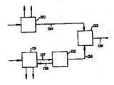
제 2 도는 산소만을 생산하는 통상적인 저온 공기분리 플랜트의 탑 배치를 예시하는 개략적 흐름도.2 is a schematic flow diagram illustrating the tower arrangement of a typical cryogenic air separation plant producing only oxygen.
제 3 도는 알곤회수의 특징이 플랜트의 최초시에 설계되고 건조되는 통상적인 산소 - 알근 플랜트의 탑 배치를 예시하는 개략적 흐름도.3 is a schematic flow diagram illustrating the tower arrangement of a typical oxygen-gneading plant in which the features of argon recovery are designed and dried at the beginning of the plant.
제 4 도는 통상적인 알근정제소의 공정배치를 예시하는 개략적 흐름도.4 is a schematic flow chart illustrating the process arrangement of a conventional alginate refinery.
제 5 도는 다중플랜트 시설에 있어서 본 발명이 새롭게 고친 알곤 회수방법을 예시하는 개략적 흐름도.5 is a schematic flow chart illustrating a method of recovering argon that the present invention has reworked in a multiplant facility.
제 6 도는 본 발명의 방법을 위한 몇가지의 선택적 냉동을 예시하는 개략적 흐름도.6 is a schematic flow chart illustrating some selective refrigeration for the method of the present invention.
제 7 도는 본 발명의 방법을 위한 2개의 선택적 공급물흐름을 예시하는 개략적 흐름도.7 is a schematic flow diagram illustrating two optional feed streams for the method of the present invention.
* 도면의 주요부분에 대한 부호의 설명* Explanation of symbols for main parts of the drawings
1 : 고압탑 2 : 저압탑1: high pressure tower 2: low pressure tower
3 : 응축장치 5 : 케틀 액체(kettle liqnid)3: condenser 5: kettle liqnid
10, 11 : 밸브 18 : 보조탑10, 11 valve 18: auxiliary tower
19, 20 : 응축기 21 : 분리기19, 20: condenser 21: separator
22 : 열교환기 23 : 압축기22: heat exchanger 23: compressor
24 : 수냉각기 28, 31 : 밸브24: water cooler 28, 31: valve
본 발명은 일반적으로 저온 공기분리 분야에 관한 것으로서, 더욱 상세하게는 공기의 저온 분리로부터 알곤의 생산에 관한 것이다.FIELD OF THE INVENTION The present invention relates generally to the field of cold air separation, and more particularly to the production of argon from cold separation of air.
알곤은 과거에 전구, 금속용접 및 기타 각종 금속학적인 용도등과 같은 다수의 용도로 사용되어 온 매우 유용한 불활성 기체이다. 알곤은 대기중에 약 1% 들어 있다. 알곤은 산소 및 질소를 생산하는 저온공기분리 플랜트에서 상업적으로 생산된다. 최근에 스테인레스 및 기타 강철제련에 알곤을 주로 이용함으로써, 알곤의 수요는 급격히 증가되었다.Argon is a very useful inert gas that has been used in a number of applications in the past, such as bulbs, metal welding and other metallurgical applications. Argon is about 1% in the atmosphere. Argon is commercially produced in cryogenic air separation plants that produce oxygen and nitrogen. With the recent use of argon mainly in smelting stainless and other steels, the demand for argon has increased dramatically.
과거에는, 제강을 위한 산소공급을 위하여 강철업에 대한 다수의 공기분리 플랜트가 세워졌었다. 이러한 플랜트들은 제강 조작장치에 인접해 있었으며, 특히 그 조작을 위해 설계되었다. 알곤의 수요는 크지 않았으므로, 다수의 이와같은 구식 공기분리 플랜트들은 알곤을 회수하는 능력이 없이 건설되었다. 이러한 공기분리 플랜트들은 알곤의 유력한 공급원이다. 그러나, 이와 같이 알곤을 회수할 수 없게 세워진 공기분리 플랜트를 알곤 회수가 가능한 플랜트로 변환하는 것은, 이러한 알곤 회수 불가능 플랜트와 오늘날의 알곤 생산 플랜트의 탑 배치가 아주 서로 다르다는 주된 이유 때문에, 매우 어려운 일이었다. 산소만을 생산하는 현존의 공기분리 플랜트를 알곤을 회수할 수 있는 공기분리 플랜트로 변환하려면, 장치의 실질적인 변경과 상당한 비용이 필요하게 된다.In the past, many air separation plants for the steel industry were built to provide oxygen for steelmaking. These plants were adjacent to the steelmaking manipulators and were specifically designed for their operation. Since the demand for argon was not great, many of these older air separation plants were built without the ability to recover argon. These air separation plants are a potent source of argon. However, converting such an argon-recoverable air separation plant into an argon-recoverable plant is very difficult because of the major difference between the tower arrangement of these non-argon-recoverable plants and today's argon-producing plants. It was. Converting an existing air separation plant that produces only oxygen to an air separation plant capable of recovering argon will require substantial modifications and significant costs of the apparatus.
더우기, 산소만을 생산하는 공기분리 플랜트를 알곤도 생산하도록 경제적으로 개조하기 위해서는 몇가지의 다른 조건들이 충족되어야 한다. 첫째, 부가되는 알곤 회수 시스템은 알곤 회수 장치가 설치되는 동안에 현존의 플랜트의 생산 중단을 최소화시키는 것이어야 한다. 둘째, 개조 회수 시스템은 현존의 알곤 정제 장치에 적합한 조제 알곤(crude argon) 생산물을 생산하는 것이어야 한다. 세째, 개조시스템은 현존의 공기분리 플랜트의 조작을 실질상 악화시키지 않는 것이어야 한다. 그밖에, 부가되는 알곤생산 시스템은 높은 %의 사용 가능한 알곤을 회수하는 것이어야 한다.Moreover, several other conditions must be met in order to be economically adapted to produce argon-producing air separation plants that produce only oxygen. First, the added argon recovery system should be such as to minimize production disruption of existing plants while the argon recovery system is installed. Second, the retrofit recovery system should be to produce crude argon products suitable for existing argon purification units. Third, the retrofit system should be one that does not substantially deteriorate the operation of existing air separation plants. In addition, the added argon production system should be one that recovers a high percentage of available argon.
그러므로, 본 발명의 목적은 알곤 회수가 불가능한 현존의 저온 공기분리 플랜트에 적합한 개선된 알곤 분리 방법을 제공하는데 있다.It is therefore an object of the present invention to provide an improved argon separation process suitable for existing low temperature air separation plants where argon recovery is not possible.
또한, 본 발명의 목적은 알곤 회수 장치가 설치되는 동안 현존의 공기분리 플랜트의 생산 중단을 최소화시키는 새로이 고쳐진 알곤 회수 방법을 제공하는데 있다.It is also an object of the present invention to provide a refreshed argon recovery method which minimizes production disruption of existing air separation plants while the argon recovery device is installed.
또한 본 발명의 목적은 높은 %의 사용 가능한 알곤을 회수할 수 있는 알곤 회수 방법을 제공하는데 있다.It is also an object of the present invention to provide an argon recovery method capable of recovering a high percentage of available argon.
또한, 본 발명의 목적은 현존의 알곤 정제 시스템에 적합한 조제알곤 생산물을 생산하는 개선된 방법을 제공하는데 있다.It is also an object of the present invention to provide an improved process for producing crude argon products suitable for existing argon purification systems.
또한, 본 발명의 목적은 현존의 공기분리 플랜트의 산소 회수율을 실질상 저하시키지 않는 새로이 바뀐 알곤회수 방법을 제공하는데 있다.It is also an object of the present invention to provide a newly changed argon recovery method that does not substantially lower the oxygen recovery of existing air separation plants.
이 분야에 통상의 지식을 가진 당업자에게 명백해질 상기의 목적 및 기타 목적들은 하기된 본 발명의 한 양상에 의해 달성된다:The above and other objects, as will be apparent to those skilled in the art, are achieved by one aspect of the present invention described below:
저압탑 및 이것과 열교환 관계에 있는 고압탑으로 이루어진 산소 생산설비에 공급가스를 도입하여, 증기와 액체를 향류적으로 유동시키는 한편 접촉시켜 분리를 달성하는 공기의 분리에 의한 알곤의 회수 방법에 있어서,In the method of recovering argon by separation of air to introduce a supply gas to the oxygen production equipment consisting of a low pressure column and a high pressure column in heat exchange relationship, and to flow the vapor and liquid in a countercurrent manner, contacting to achieve separation ,
(A) 약 10% 내지 18%의 알곤, 많아야 약 0.5%의 질소, 그리고 그 나머지 주로 산소로 이루어져 있는 흐름이고, 주 플랜트에 대한 공급공기 유속의 약 3 내지 9%에 해당하는 유속을 갖는 흐름을 저압탑으로부터 배출시키는 단계 :(A) a flow consisting of about 10% to 18% argon, at most about 0.5% nitrogen, and the remainder mainly oxygen, having a flow rate corresponding to about 3 to 9% of the feed air flow rate to the main plant Evacuating from the low pressure tower:
(B) 탑상 응축기 및 탑저 응축기를 갖는 알곤탑이고, 하기된 (1) 내지 (4)의 단계들로 이루어지는 독립적인 열펌프회로에 의해 작동되는 알곤탑에 상기의 흐름을 공급물로 도입하는 단계 : (1) 냉각 압축된 열펌프유체를 열교환기에 증기상태로 도입하여 고압냉각 상태로 냉각하는 단계 : (2) 상기의 고압냉각 증기를 탑저 응축기에 도입하여 액체상태로 응축하는 단계 : (3) 액체 열펌프유체를 팽창시키는 동시에 탑상 응축기에 도입하여 기화시키는 단계 : (4) 열펌프유체를 알곤탑으로부터 증기 상태로 회수하는 동시에 이것을 상기 단계(1)의 열교환기에 도입하여 가온하는 단계 :(B) introducing the stream as a feed to an argon tower which is an argon tower having a columnar condenser and a columnar condenser and is operated by an independent heat pump circuit consisting of the steps of (1) to (4) described below; (1) introducing a cooled and compressed heat pump fluid into a heat exchanger in a vapor state and cooling it in a high pressure cooling state: (2) introducing the high pressure cooling steam into a bottom condenser to condense it into a liquid state: (3) Expanding and evaporating the liquid heat pump fluid at the same time into the tower condenser: (4) recovering the heat pump fluid from the argon column in a vapor state and introducing it into the heat exchanger of step (1) to warm it:
(C) 알곤탑에서 상기의 공급물을 정류시켜 알곤부화(argon - rich)부분과 산소부화(oxygen - rich)부분으로 분리하는 단계 :(C) rectifying the feed in the argon column to separate the argon-rich and oxygen-rich portions:
(D) 상기 알곤부화 부분중의 최소한 일부를, 최소한 96몰% 알곤함유 생산물로 알곤탑으로부터 회수하는 단계 : 그리고(D) recovering at least a portion of the argon hatching portion from the argon tower with at least 96 mole percent argon containing product: and
(E) 상기 산소부화 부분중의 최소한 일부를, 최소한 99몰%의 산소농도를 갖는 산소생성물로 회수하는 단계가 포함되는 것을 개선으로 하는, 공기의 분리에 의한 알곤의 회수방법.(E) recovering argon by separation of air, further comprising recovering at least a portion of the oxygen enriched portion as an oxygen product having an oxygen concentration of at least 99 mole percent.
본 발명의 또다른 양상은 하기된 바와 같다.Another aspect of the invention is as follows.
고압탑 및 이것과 열교환 관계에 있는 저압탑으로 이루어지는 공기 분리에 의한 알곤의 제조장치에 있어서,In the manufacturing apparatus of argon by air separation which consists of a high pressure tower and the low pressure tower which exchanges heat with this,
(A) 도관수단에 의해 상기 저압탑에 연결되어 있고 탑상 및 탑저 응축기를 구비하는 알곤생산용 탑 :(A) Argon production tower connected to the low pressure column by conduit means and having a tower top and a bottom condenser:
(B) 열펌프유체를 압축하기 위한 수단 :(B) Means for compressing heat pump fluid:
(C) 압축된 열펌프유체를, 탑저 응축기에 도입하여 액화시키기 전에, 열펌프유체를 냉각시키기 위한 열교환기 수단 :(C) Heat exchanger means for cooling the heat pump fluid before introducing the compressed heat pump fluid into the bottom condenser and liquefying:
(D) 액체 열펌프유체의 기화를 위한 탑상 응축기에 액체 열펌프유체를 이송하기 위한 수단 : 그리고(D) Means for conveying liquid heat pump fluid to a tower condenser for vaporization of liquid heat pump fluid: and
(E) 증기 열펌프유체의 가온을 위한 열교환기 수단에 증기 열펌프유체를 이송하기 위한 수단이 포함되는 것을 개선으로 하는, 공기의 분리에 의한 알곤의 회수장치.(E) A device for recovering argon by separation of air, with an improvement that the heat exchanger means for heating the steam heat pump fluid includes means for transferring the steam heat pump fluid.
탑(column)이란 용어는 증류 또는 분류탑, 즉 유체 혼합물을 분리하기 위해 액상 및 증기상이 향류로 접촉되는 탑 또는 지역을 의미한다. 접촉은 예를 들어 탑 내부에 일련의 수직으로 설치된 트레이(trag) 또는 플레이트(plate)상에서, 또는 그렇지 않으면, 탑 내에 채워진 충진요소 상에서 증기상과 액체상이 접촉함으로써 이루어진다. 앞서 말한것의 보다 넓은 이해를 위하여, 다음 문헌[화학공학자 핸드북, 5판, R. H. Perry 및 C. H. Chilton 편집, 뉴욕소재 McGraw - Hill 출판사, 13장, "증류" B. D. Smith 등, 13-3항, 연속 증류공정]을 참조한다.The term column refers to a distillation or fractionation tower, ie a tower or region in which the liquid and vapor phases are contacted countercurrently to separate the fluid mixture. The contact is made, for example, by contacting the vapor and liquid phases on a series of vertically installed trays or plates inside the tower, or else on the filling element filled in the tower. For a broader understanding of the foregoing, see: Chemical Engineers Handbook, 5th Edition, edited by RH Perry and CH Chilton, McGraw-Hill Publishers, New York, Chapter 13, "Distillation" BD Smith et al., Paragraphs 13-3, continuation Distillation process].
이중탑이란 용어는 저압탑 및 그 상단부가 저압탑의 하단부와 열교환 관계에 있는 고압탑을 의미하는데 사용된다. 이중탑의 예들은 다음 문헌[Ruheman 저, "기체의 분리", "University Press, 1949]에 나타나 있다.The term double column is used to mean a high pressure tower in which the low pressure tower and its upper end are in heat exchange relationship with the lower end of the low pressure tower. Examples of double towers are shown in Ruhreman, "Separation of Gases", "University Press, 1949".
열펌프회로란 용어는 순환유체 장치를 의미하기 위해 사용된다. 열은 낮은 온도에서 제거되고, 높은 온도에서 부가된다. 통상적으로, 열펌프장치는 열을 제거하기 위한 순환유체(또는 작동매체)의 증발 및 열을 부가하기 위한 유체의 응축을 포함한다.The term heat pump circuit is used to mean a circulating fluidic device. Heat is removed at low temperatures and added at high temperatures. Typically, a heat pump device includes evaporation of a circulating fluid (or working medium) to remove heat and condensation of a fluid to add heat.
본 발명은 현존의 저온 공기분리 방법 및 장치들을 변형하여 알곤을 생산하기 위한 방법 및 장치를 제공하는데, 이들 방법 및 장치는 산소도 생산하며 알곤의 경제적 회수를 가능하게 한다. 본 발명의 방법 및 장치는 적어도 96몰%의 순도를 갖는 알곤을 생산하여, 이들 알곤이 현존의 알곤정제소에 비교적 쉽게 이용될 수 있게 한다. 또한 본 발명의 방법 및 장치는 적어도 99몰% 의 순도를 갖는 산소도 생산하여, 이들 산소가 산소만을 생산하는 현존의 플랜트로부터 생산된 생산물과 직접 서로 혼합될수 있게 한다.The present invention provides a method and apparatus for producing argon by modifying existing low temperature air separation methods and apparatuses, which also produce oxygen and enable economic recovery of argon. The method and apparatus of the present invention produce argon having a purity of at least 96 mole percent, allowing these argon to be used relatively easily in existing argon refineries. The method and apparatus of the present invention also produce oxygen having a purity of at least 99 mole percent so that these oxygen can be directly mixed with the products produced from existing plants that produce only oxygen.
본 발명의 개선된 방법은 독자적인 열펌프회로에 의해 작동되는, 보조적인 두 부분으로 된 조제알곤탑을 이용한다. 알곤탑 공급물은 현존의 공기분리 플랜트의 저압탑 내의 중간 지점에서 배출된 것으로서, 본질상 최소의 질소함량을 갖는 알곤 - 산소 혼합물이다. 이 공급물흐름은 알곤탑 내부에서 두개의 생산물 흐름으로 분리된다. 알곤탑의 탑저로부터 배출된 하나의 생산물 흐름은 공기분리 플랜트의 저압탑으로부터 배출된 산소생산물 흐름과 유사한 조성을 갖는 생산물 산소흐름이다. 다른 생산물 흐름은 현존의 알곤정제 시스템에 공급될 수 있는 조성을 갖는 조제알곤 생산물이다.The improved method of the present invention utilizes an auxiliary two-part formulated column operated by a proprietary heat pump circuit. The argon column feed is discharged at an intermediate point in the low pressure column of an existing air separation plant, which is essentially an argon-oxygen mixture with a minimum nitrogen content. This feed stream is separated into two product streams inside the argon tower. One product stream exiting the tower bottom of the argon column is a product oxygen stream having a composition similar to that of the oxygen product stream exiting the low pressure tower of the air separation plant. Another product stream is a crude argon product having a composition that can be fed to existing argon refining systems.
알곤탑 시스템은 냉동공급원을 포함할 수 있는데, 이 냉동 공급원은 알곤탑의 탑상 응축기에 또는 열펌프순환회로의 다른 적절한 지점에 부가된 액체질소 일 수 있거나, 또는 알곤탑의 탑저 응축기에 있는 액체 산소일 수도 있으며, 또는 열펌프회로에서 순환유체중의 일부의 터어빈 팽창에 의해서도 냉동이 제공될 수 있다. 냉동공급원과 이것을 알곤탑 시스템에 공급하는 수단은 이 분야에 통상의 지식을 가진 당업자가 판단할 문제이며, 특히 장치의 이용성 및 액체 공급원의 이용성에 의존한다.The argon tower system may comprise a refrigeration source, which may be liquid nitrogen added to the tower top condenser of the argon tower or at another suitable point in the heat pump circuit, or liquid oxygen in the tower bottom condenser of the argon tower. Alternatively, refrigeration may also be provided by expansion of the turbine in a portion of the circulating fluid in the heat pump circuit. The refrigeration source and the means for supplying it to the argon tower system are issues that will be appreciated by those skilled in the art, in particular depending on the availability of the device and the availability of the liquid source.
알곤탑에 공급된 공급물은 저압탑의 탑저를 통해 또는 생산물 산소 배출위치 상부의 지점을 통해 주 플랜트의 저압탑으로부터 배출된 것이다. 알곤탑에 이송된 공급물의 양은, 주 플랜트 또는 산소 생산설비에 공급된 공급물의 양에 기초하여, 3 내지 9부피%, 바람직하게는 5 내지 7부피%이다. 공급물흐름은 이것의 조성이 10 내지 18%의 알곤, 바람직하게는 12 내지 16%의 알곤을 함유하는 저압탑 내의 지점을 통해 저압탑으로부터 배출된 것이다. 공급물흐름중의 질소함량은 0.5%를, 바람직하게는 0.2%를 초과하지 말아야 한다. 나머지는 주로 산소로 이루어져 있다.The feed supplied to the argon tower is withdrawn from the low pressure tower of the main plant through the tower bottom of the low pressure tower or through a point above the product oxygen discharge location. The amount of feed delivered to the argon column is 3 to 9% by volume, preferably 5 to 7% by volume, based on the amount of feed to the main plant or oxygen production facility. The feed stream is discharged from the low pressure column through a point in the low pressure column whose composition contains 10 to 18% argon, preferably 12 to 16% argon. The nitrogen content in the feed stream should not exceed 0.5%, preferably 0.2%. The rest consists mainly of oxygen.
알곤탑을 만족스럽게 작동시키고 조제알곤 및 생산물 산소를 위한 적당한 순도를 얻기 위하여, 열펌프 유체회로는 공급물흐름유속의 3 내지 7배, 바람직하게는 4 내지 5배로 순환된다. 산소, 질소, 알곤, 조제알곤 혼합물 또는 청정 및 건조공기와 같은 어떤 적당한 유체가 열펌프유체로 사용될 수 있다. 바람직한 열펌프유체는 질소이다.In order to operate the argon column satisfactorily and to obtain adequate purity for the preparation argon and product oxygen, the heat pump fluid circuit is circulated at 3 to 7 times, preferably 4 to 5 times, the feed flow rate. Any suitable fluid may be used as the heat pump fluid, such as oxygen, nitrogen, argon, crude argon mixture or clean and dry air. Preferred heat pump fluid is nitrogen.
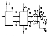
본 발명의 개선된 방법은 도면들을 참조로 더 상세히 설명된다. 제 1 도는 본 발명의 방법 및 장치의 바람직한 구체예를 예시한다. 열교환기 및 이와 관련된 가온 단부장치와 같은 기타의 모든 부분들은 본 발명의 방법 및 장치의 조합에 영향을 미치지 않으므로, 산소만을 생산하는 현존의 공기분리 플랜트의 탑부분만이 예시되었다. 그러나, 부가된 알곤회수 방법 및 장치의 모든 공정부분들은 배치를 충분히 설명하기 위해 도시되었다. 주 공기분리 플랜트에는, 저압탑(2)와 연결된 고압탑(1) 및 이들을 서로 연결하는 응축장치(3)이 나타나 있다. 공급물 공기흐름(4)는 고압탑의 탑저를 통해 고압으로 탑부분에 도입된다. 이 고압공기는 고압탑 V의 트레이 부분에서 단액체(shelf liquid) (9)와 케틀 액체(kettle liquid) (5)로 예비 분리된다. 고압탑 V의 탑상을 통해 상승하는 증기(6)은 응축장치(3)에서 응축되어 액체흐름(7)로 배출된다. 이어서 이 액체흐름(7)은 부분(8)과 부분(9)로 나누어져서, 부분(8)은 고압탑의 환류로 사용되는 한편 나머지부분(9)는 저압탑의 탑상을 위한 환류로 사용된다. 고압탑에서 저압탑으로 이송되는 이러한 액체 흐름은 존재하는 흐름들에 의해 냉각될수 있지만 이러한 공정의 세부적인 것은 도시되지 않았다. 환류흐름(9)는 밸브(10)을 통해 저압탑의 탑상에 팽창되는 한편 환류흐름(5)는 수개 트레이 아래에 위치한 밸브(11)을 통해 팽창된다. 이들 두 액체흐름 및 공기플랜트 냉동에 사용되었기 때문에 터빈 공기부분으로 통상 일컬어지는 저압 공기흐름(13)은 저압탑에 도입되어 생산물흐름(14)와 폐기흐름812)로 분리된다. 그밖에, 주 분리탑은 저압탑으로부터 흐름(17)의 배출 및 생산물 산소를 위한 흐름(15)의 귀환을 수행한다. 이들 두 흐름을 위해서는 현존의 비알곤 생산 플랜트를 본 발명의 방법 및 장치에 의해 알곤 생산 플랜트로 변환시키는 것이 필요하다. 공급물흐름(17)은 비교적 높은 알곤함량을 가지고 있으며 나머지 성분은 거의 산소로 이루어져 있는 흐름이다. 흐름(17)중에서 단지 작은 일부분만이 질소이다.The improved method of the present invention is described in more detail with reference to the drawings. 1 illustrates a preferred embodiment of the method and apparatus of the present invention. All other parts, such as heat exchangers and associated heating end devices, do not affect the combination of the method and apparatus of the present invention, so only the top part of an existing air separation plant producing only oxygen is illustrated. However, all process parts of the added argon recovery method and apparatus are shown to fully describe the batch. In the main air separation plant, there is shown a high pressure tower 1 connected to a low pressure tower 2 and a condenser 3 connecting them to each other. The feed air stream 4 is introduced into the tower section at high pressure through the tower bottom of the high pressure tower. This high pressure air is preliminarily separated into a shelf liquid 9 and a kettle liquid 5 in the tray portion of the high pressure column V. The vapor 6 rising through the tower of the high pressure tower V is condensed in the condenser 3 and discharged into the
귀환통로(15)는 생산물 산소품질의 증기흐름이므로 (14)와 결합되어 플랜트 생산물 산소흐름(16)을 형성할 수 있다. 일반적으로, 이러한 플랜트 생산물 산소흐름은 직접 사용에 적당하다.The return passage 15 is combined with (14) because of the product oxygen quality of the steam flow can form the plant product oxygen flow (16). In general, these plant product oxygen flows are suitable for direct use.
이제 시스템의 보조탑부분에 대해 설명하면, 주플랜트의 저압탑으로부터 배출되는 공급물흐름(17)은 보조탑(18)의 중간 지점에 도입된다. 주로 알곤 - 산소로 된 공급물흐름(17)은 두개의 생산물품질 흐름으로 분리된다. 제 1 흐름은 보조탑의 탑저로부터 배출된 것으로서, 주 플랜트의 생산물 산소에 부가될수 있을 정도의 순도를 갖는다. 이 흐름(15)는 존재하는 저압탑으로 부터의 생산물 산소 배출지점 하류를 통해 주 플랜트에 귀환된다. 다른 생산물흐름(38)은 조제알곤 생성물이다. 이 조제알곤흐름은 공급물흐름(17)에 존재했던 실질상 전부의 알곤을 함유하며, 동시에 그 흐름에 소량으로 존재했던 실질상 전부의 질소 및 약간의 최소 산소함량을 갖는다. 이 조제알곤 생산물 흐름은 알곤생산 공기분리 플랜트로부터 대개 얻어진 것들와 필적하는 순도를 갖는다.Referring now to the sub tower portion of the system, the feed stream 17 exiting the low pressure tower of the main plant is introduced at the midpoint of the sub tower 18. The feed stream, primarily argon-oxygen (17), is separated into two product quality streams. The first stream is discharged from the bottom of the sub-column and has a purity that can be added to the product oxygen of the main plant. This stream 15 is returned to the main plant downstream of the product oxygen outlet from the existing low pressure tower. Another product stream 38 is the crude argon product. This preparation argon flow contains all of the substantial phase argon present in the feed stream 17, while at the same time having a slight minimum oxygen content of all of the substantial phase present in the stream. This crude argon product stream has a purity comparable to that usually obtained from argon producing air separation plants.
공급물흐름(17)의 분리를 달성하기 위한 보조 조제알곤탑의 작동방법은 열펌프회로의 설명에 의해서 더 잘 이해될 수 있다. 질소와 같은 적당한 유체는 주위온도에서 압축되고, 그 후에 수냉각기(24)를 통과하여 고압흐름이 흐름(25)와 같은 주위조건으로 복귀된다. 이 흐름은 열교환기(22)에 의해 냉각되어 흐름(26)과 같은 고압냉각 상태로 냉각된다. 이 흐름(26)은 알곤탑의 탑저에 있는 응축기(19)에 도입되어 응축열을 잃으면서 응축되고 탑저에서 액체산소를 기화시킨다. 이러한 응축 - 비등작용은 조제알곤탑의 탑저를 위한 증기환류를 생성하는 역할을 한다. 고압액체흐름(27)은 밸브(28)에서 팽창된 후 도관(29)를 경우하여 탑상 환류응축기에 도입된다. 이 환류응축기 내에서, 액체는 증발하여 도관(32)를 통해 응축기를 떠난후 열교환기(22)에 도입되어 흐름(33)과 같은 저압주위 상태로 다시 가온될 수 있다. 알곤탑 탑상의 저압챔버에 위치한 축기(20)은 조제 알곤탑의 탑상으로부터의 탑증기(36)을 응축시켜 도관(37)을 통해 액체 - 증기분리기(21)로 이송하기 위해 사용된다. 이 분리기는 액체를 유지하는 기능 및 이 액체를 도관(39)를 통해 환류로 조제알곤탑의 탑상에 이송시키는 한편 나머지 증기를 도관(39)를 통해 조제알곤 생산물로 제거하는 기능을 가진다. 탑상응축기(20) 및 이와 관련된 액체 증기분리기(21)에 대해 도시된 특정의 배치는 응축기 내부에 비응축성 질소가 축적되는 것을 방지하기 때문에 본 발명을 위해 바람직한 것이다. 도시된 흐름회로는 질소를 조제알곤 생산물흐름(38)과 함게 제거하려는 경향을 갖는다. 그러나, 이렇게 도시된 배치가 바람직 할지라도, 반드시 필요한 것은 아니다. 조제알곤 생산물(38)은 상승중의 탑증기흐름(36)의 일부로서 제거될 수 있다. 이어서 그 나머지 부분은 응축기(20)에서 완전히 응축되어 분리탑에 환류액체로 귀환될 수 있다. 그 다음, 앞서 지적한 바와 같이, (33)에서와 같은 저압 주위조건 흐름은 압축기(23)에 의해 압축되어 조제알곤탑을 조작하는데 필요한 열 및 냉동을 공급할 수 있다. 이러한 열펌프회로는 알곤탑의 탑저에서는 열을, 그리고 탑상에서는 냉동을 공급할수 있지만, 근본적으로나마 전체 시스템을 낮은 조작온도 수준으로 유지하는데 필요하게 될 냉동을 공급하지는 않는다. 알곤조제 시스템을 갖는 조작온도 수준으로 유지하는 이러한 기능은 (30)에서와 같은 액체를 부가함으로서 달성될수 있다(필요하다면, 이러한 액체부가는 응축기압력 수준에 의존하여 밸브(31)을 통해 부가될수 있다). 탑상 응축기에 부가된 액체는 대기로부터의 열유입에 의해 결정되는 바와 같이 기화된후, 증기는 도관(29)를 통해 출구도관(32)로 들어가는 유체와 결합될 것이다. 관련장치의 유체누출 및 관련장치에 대한 열 누출에 의존하여, 부가된 액상 유체의 일부는 도관(32)에 의해 도시된 바와 같은 적절한 제어에 의하여 배출될 수 있다. 포위된 회로로부터 가온단부 배출구를 통해 배출되는 과잉유체의 이러한 배치는 액체로부터의 모든 사용 가능한 냉동, 즉 잠열 및 현열을 이용하여 시스템을 냉각 조작온도 수준으로 유지한다는 점에서 유익하다. 제 1 도에서와 같이 도시된 시스템은 본 발명의 방법 및 장치에 대한 모든 필수적인 요소를 도시하고 있으며, 현존의 공기분리 플랜트의 생산중단 기간을 최소화시키고, 조제알곤 생산물 회수율을 최대화시키고, 바람직한 안전조작을 제공하는 장점을 갖는다.The method of operating the auxiliary preparation argon column to achieve separation of the feed stream 17 can be better understood by the description of the heat pump circuit. A suitable fluid, such as nitrogen, is compressed at ambient temperature and then passes through a water cooler 24 to return the high pressure flow to ambient conditions such as flow 25. This flow is cooled by heat exchanger 22 and cooled to a high pressure cooling state such as flow 26. This stream 26 is introduced into the condenser 19 at the bottom of the argon column to condense without losing the heat of condensation and vaporize the liquid oxygen at the bottom. This condensation-boiling action serves to generate steam reflux for the bottom of the preparation argon column. The high
본 발명의 개선된 방법의 이점들을 충분히 이해시키기 위해서는 산소만을 생산하는 통상적인 플랜트 탑 구조를 설명하고 이것을 통상적인 알곤플랜트 탑 구조와 비교하는 것이 유용하다. 제 2 도는 통상적인 산소만의 플랜트 탑 부분을 도시하고 있다. 그 플랜트는 고압탑(50) 및 이와 연결된 저압탑(51)로 이루어져 있다. 두 탑들은 주 응축기(52)에 의해 서로 연결된다. 고압공기는(53)을 통해 탑저로 들어가서 높은 질소함량의 증기흐름(54)와 높은 산소함량의 흐름(58)로 분리된다. 흐름(54)는 응축기(52)에서 응축되어 액체흐름(55)를 통해 응축기를 떠난다. 이어서, 이 액체흐름은 두부분으로 나뉘어진다. 한부분(57)은 고압탑을 위한 환류로 사용되는 한편, 다른 부분(56)은 밸브(60)을 통해 팽창된 후 저압탑의 상부에 이송된다. 높은 산소함량부분(58)은 밸브(59)를 통해 저압탑에 팽창된다. 그보다 더 아래의 지점을 통해서는 저압공기(62)가 저압탑에 도입된다. 이 저압공기(62) 또는 터빈 공기부분은 플랜트의 열교환기 부분에서 터빈 팽창되는 공급공기 부분으로서, 공기분리 플랜트를 위한 냉동작용을 전개한다. 저압탑에 도입되는 모든 세 공급물, 즉 두 액체 공급물 및 증기는 두 흐름으로 분리된다. 한흐름(63)은 생산물 산소 흐름으로서 저압탑의 탑저로부터 배출되는 한편, 다른 흐름(61)은 폐기 흐름으로서 탑상으로부터 배출된다. 열교환기들(도시하지 않음)은 고압탑과 저압탑 사이의 액체 환류흐름들을 다 냉각할 것이다.To fully understand the advantages of the improved process of the present invention, it is useful to describe a conventional plant tower structure that produces only oxygen and compare it with a conventional argonplant tower structure. 2 shows a plant top portion of a conventional oxygen only. The plant consists of a high pressure tower 50 and a low pressure tower 51 connected thereto. The two towers are connected to each other by the main condenser 52. The high pressure air enters the column bottom through the 53 and is separated into a high nitrogen content vapor flow 54 and a high oxygen content flow 58. Flow 54 condenses in condenser 52 and leaves condenser through liquid flow 55. This liquid flow is then divided into two parts. One portion 57 is used as reflux for the high pressure tower, while the other portion 56 is expanded through the valve 60 and then transferred to the top of the low pressure tower. The high oxygen content portion 58 is expanded to the low pressure column through the valve 59. The lower pressure air 62 is introduced into the low pressure column through the lower point. This low pressure air 62 or turbine air portion is the feed air portion that is turbine expanded in the heat exchanger portion of the plant, which develops the refrigeration for the air separation plant. All three feeds introduced into the low pressure column, the two liquid feeds and the vapor, are separated into two streams. One flow 63 exits the bottom of the low pressure column as product oxygen flow, while the other flow 61 exits from the tower as waste stream. Heat exchangers (not shown) will cool the liquid reflux flows between the high and low pressure towers.
도시된 바와 같이, 탑구조는 산소만을 생산하는 유형의 공기 플랜트에 대한 것이다. 다시 말하면, 원하는 생산물이 공업적 조작에 일반적으로 필요한 순도의 기체산소인 공기분리 플랜트에 대한 것이다. 이러한 탑구조는 저압탑을 위한 세부분 I, II 및 III그리고 고압탑을 위한 한부분 IV를 사용함을 알 수 있다.As shown, the tower structure is for an air plant of the type producing only oxygen. In other words, the desired product is for an air separation plant, which is a gaseous oxygen of purity generally required for industrial operation. It can be seen that this tower structure uses subdivisions I, II and III for the low pressure tower and part IV for the high pressure tower.
산소 및 알곤을 생산하는 공기분리 플랜트에 이용되는 통상적인 탑구조는 제 3 도에 도시되어 있다. 제 3 도로부터 알 수 있듯이, 이 구조는 고압탑(70) 및 이와 연결된 저압탑(71) 그리고 이들을 연결하는 응축장치(74)를 사용하고 있다. 알곤 생산물을 생산하는데 필요한 것으로 부가되는 것은 조제알곤탑(72)이다. 고압공기(75)는 고압탑의 탑저로 들어가서 트레이 부분을 통과하여 높은 질소함량의 증기흐름(77)과 높은 산소함량의 산소흐름(76)으로 분리된다. 높은 질소함량의 증기흐름(77)은 열교환기(74)로 들어가서 응축액체(78)로 배출된다. 이 응축액체(78)은 두부분으로 나누어져서, 한부분(79)는 고압탑을 위한 환류로 귀환되고 다른 하나(80)은 저압탑의 탑상에 환류로 이송된다. 높은 질소함량의 환류 흐름이 밸브(81)을 통해 팽창되어 산소만을 생산하는 플랜트에 관한 저압탑의 탑상에 도입되지만, 고압탑의 탑저로부터의 높은 산소함량의 환류흐름은 조제알곤탑의 탑상에 있는 응축기(73)에 이송된다. 높은 산소함량의 환류흐름은 밸브(89)를 통해 팽창되어 응축기(73)에서 부분적으로 기화된후, 액체 - 증기 혼합물흐름(88)로 저압탑에 도입된다. 저압탑은 저압 공기공급물(83)을 가지는데, 이 공급물은 플랜트 냉동에 이용되는 공기부분이다. 그러나, 이 저압탑은 저압 공기흐름(83)과 생산물 산소흐름(84) 사이에 두개의 부가적인 공급지점을 갖는다는 점에서 산소만을 생산하는 플랜트의 저압탑과 비교된다. 중간지점을 통해, 증기 공급물흐름(85)는 저압탑으로부터 배출되어 조제알곤탑(72)의 탑저에 도입되고, 거기서 높은 알곤함량의 탑상 알곤으로 농축된다. 이러한 증기중의 일부는 탑상 응축기(73)에서 응축되어 탑을 위한 환류로 쓰여지는 한편, 나머지 증기는 조제알곤 생산물(87)로 배출된다. 이어서 증기 환류흐름은 탑(72)의 탑저까지 계속 흘러서 저압탑에 흐름(86)으로 재도입 된다. 총괄적으로 보면, 이러한 시스템은 저압탑으로 부터의 생산물 산소흐름(84), 알곤탑으로 부터의 알곤생산물(87), 그리고 저압탑의 탑상으로부터의 폐기흐름(82)를 생산한다. 이러한 배치는 네부분의 저압탑 I, II, III, IV 그리고 한부분의 고압탑 V, 그밖에 한부분의 알곤탑 VI을 필요로 함을 알 수 있다. 이와 같은 통상적인 산소 - 알곤탑 배치는 내부공정 흐름만을 사용하여 공기공급물을 산소와 알곤제품으로 공기공급물의 분리를 가능하게 하는 것으로서, 효과적인 분리시스템이다.A typical tower structure used in an air separation plant that produces oxygen and argon is shown in FIG. As can be seen from FIG. 3, this structure uses a high pressure tower 70, a
산소만을 생산하는 통상적인 탑구조와 통상적인 산소 - 알곤탑 구조를 비교함으로써, 이들 두 시스템을 위한 탑배치는 서로 아주 다름을 알 수 잇다. 나중에 설명되는 바와 같이, 알곤탑을 주 공기분리 플랜트에 연결하는 부가적인 공급물흐름들은, 산소만을 생산하는 통상적인 탑구조를 산소 - 알곤탑 구조로 변환시키는 것에 매력을 느끼지 못하게 만든다.By comparing the conventional oxygen-argon column structure with a conventional tower structure that produces only oxygen, it can be seen that the top arrangements for these two systems are very different from each other. As will be explained later, additional feed flows connecting the argon tower to the main air separation plant make it unattractive to convert the conventional tower structure, which produces only oxygen, into an oxygen-argon tower structure.
통상적인 산소 - 알곤탑 장치로부터 생산되는 알곤 조제알곤 생산물(87)은 제 4 도에 도시된 바와 같이 정제될 수 있다. 도시된 바와 같이, 조제알곤흐름(107)은 열교환기(100)에서, (108)에서와 같은 주위온도 저압상태로 가온된다. 이어서, 이 저압증기는 압축기(101)에 의해 압축되고 수냉각기(도시되지 않음)에 의해 냉각되어 (109)에서의 고압주위 조건에 있게 된다. 이 지점에서, 작은 수소흐름(110)이 부가되고, 결합수소, 조제생산물 흐름(111)은 촉매반응기(102)에 도입된다. 이 반응기 내에서, 조제알곤 생산물의 산소 성분과 수소가 반응하므로써 흐름(112)에 유리산소가 함유되어 있지 않으며 대신에 수분이 함유되어 있다. 이어서 이 수분은 건조기(103)에서 제거되어 흐름(113)은 단지 알곤과 질소(그리고 아마 약간의 과잉수소)만을 함유한다. 이어서 이 흐름은 열교환기(100)에서 냉각되고 이렇게 냉각된 고압흐름(114)은 응축기(106)에서 응축되고 액체(115)는 밸브(116)을 통해 팽창된 후 도관(117)을 통하여 질소 배제탑(104)에 공급물로 이송된다. 제거된 질소는 질소 배제탑의 탑상에서 냉각되고 응축기(105)에 이송되어 (119)를 통해 배출된다.The argon
탑(104)의 탑저에서 응축되는 알곤 질소흐름과 탑상에서 냉각되는 액체질소의 조합은 질소가(120)에서 배제되고 그 순도의 액체알곤의 탑저를 통해 흐름(121)로 제거될 수 있도록 탑을 작동시키는 역학을 한다.The combination of argon nitrogen flow condensing at the bottom of the
본 발명의 방법 및 장치에 따른 최소한 두 가지의 이점은 제 5 도에 개략적으로 예시된다. 이 도면은 현존하는 산소만의 공기분리 플랜트(131)과 현존하는 산소 - 알곤 공기분리 플랜트(130)을 연결하는 플랜트 위치에서, 본 발명의 알곤 회수방법 및 장치를 위한 보조탑의 부가를 보여준다. 현존하는 알곤 플랜트와 본질상 동일한 순도를 갖는 조제알곤(35)를 생산하기 위한 본 발명의 보조탑 시스템의 능력은 그들 두 플랜트들에 대한 중심적 또는 공통적 알곤전제를 가능하게 한다. 그래서, 보조탑으로 부터의 조제알곤(135)는 산소 - 알곤 플랜트로 부터의 조제알곤(134)와 결합되고 공통 알곤정제소(133)에서 처리되어 정제된 알곤(136) 생산물이 생산될 수 있다. 보조 알곤 회수방법, 이러한 특징은 산소만을 생산하는 플랜트가 알곤도 회수할 수 있게 변환되는 상황에서 현존의 산소 - 알곤 플랜트와 함께 이용될 수 있는 것으로서 현존의 알곤정제소의 사용을 가능하게 하거나 또는 통상적인 알곤정제 시스템의 사용을 가능하게 한다는 점에서 흥미롭다.At least two advantages of the method and apparatus of the present invention are schematically illustrated in FIG. This figure shows the addition of an auxiliary tower for the argon recovery method and apparatus of the present invention at a plant location connecting the existing oxygen only air separation plant 131 and the existing oxygen-argon air separation plant 130. The ability of the subtower system of the present invention to produce crude argon 35 having essentially the same purity as existing argon plants enables a central or common argon pretreatment for those two plants. Thus, the argon 135 from the auxiliary column may be combined with the argon 134 from the oxygen-argon plant and processed in a common argon refinery 133 to produce a purified argon 136 product. Auxiliary argon recovery method, this feature can be used with existing oxygen-argon plants in situations where oxygen-only plants are converted to recover argon, allowing the use of existing argon refiners or conventional It is interesting in that it enables the use of argon refining systems.
본 발명에 따른 개선된 방법의 또 하나의 이점은 제 5 도에 개략적으로 나타나 있다. 도시된 바와 같이, 산소만을 생산하는 현존의 주 플랜트(131)과 보조 알곤탑(132)를 연결하는 단지 두개의 흐름은 공급물흐름(137)과 산소생산물 귀환흐름(138)이다. 산소만을 생산하는 현존의 플랜트와 알곤회수를 위한 보조탑 사이의 최소공정흐름 연결의 이러한 특징은 본 발명의 매우 편리한 특징이다. 흐름 연결이 최소이기 때문에 현존의 플랜트의 조작을 계속하면서 그 근처에 별개의 케이싱(casing)으로 개조 보조탑 설비를 건설하는 것이 가능하다. 산소만을 생산하는 주 공기분리 플랜트는 두흐름 연결을 달성하는데 필요한 비교적 짧은 시간동안 가동이 중지되어야 한다. 그러므로, 이러한 특징은 개조 알곤 회수장치를 건설하는 동안 현존의 주 공기분리 플랜트의 조업중단을 감소시키는 주된 경제적 이점을 갖는다. 이러한 점은 제 2 도와 3 도의 탑 배치를 비교해보면 더 잘 이해될 수 있다. 산소만을 생산하는 탑 구조를 통상적인 산소 - 알곤 생산탑 구조로 변환하기 위해서는 주 분리탑이 주로 변형되어야하므로 상당한 플랜트 조업중단이 수반됨을 알 수 있다.Another advantage of the improved method according to the invention is shown schematically in FIG. 5. As shown, the only two streams connecting the existing main plant 131 and the auxiliary argon tower 132 that produce only oxygen are the feed stream 137 and the oxygen product return flow 138. This feature of the minimal process flow connection between an existing plant producing only oxygen and an auxiliary tower for argon recovery is a very convenient feature of the present invention. Since the flow connection is minimal, it is possible to build retrofitting tower construction with separate casings nearby while continuing to operate the existing plant. The main air separation plant, producing only oxygen, should be shut down for a relatively short period of time necessary to achieve a double flow connection. Therefore, this feature has a major economic advantage of reducing downtime of existing main air separation plants during construction of retrofit argon recovery units. This can be better understood by comparing the second and third degree tower layouts. It can be seen that the conversion of the tower structure that produces only oxygen to the conventional oxygen-argon production tower structure involves significant plant downtime, since the main separation tower must be modified primarily.
보조 알곤탑 방법의 부가적인 융통성은 제 6 도에 개략적으로 예시되었다. 이 도면은 새롭게 고친 알곤 회수 방법이 냉동 공급원에 관하여 상당한 융통성을 가짐을 보여준다. 도면 제6a도에 나타난 공정 구성은 알곤탑의 냉동을 위해 액체 질소를 이용한다. 도면에 나타난 바와 같이, 주 공기분리 플랜트(140)은 보조탑 공급물흐름(142)와 귀환 산소흐름(143)에 연결된다. 액체질소 냉동제(145)는 보조탑의 탑상 응축기에 도입되어 흐름(146)을 지나 열교환기(148)을 통해 귀환된다. 가온된 질소흐름(150)은 열펌프회로 내에서의 질소와 액체질소 냉매부가에 의한 질소를 포함한다. 압력조건을 유지하기 위하여, 질소를 (149)에서와 같이 배출되고, 나머지 질소(151)은 압축기(153)에 의해 압축된후, 흐름(152)로 고압에 귀환된다. 이 흐름은 냉각되어 냉각 고압질소(147)로 들어가는데, 이 질소는 보조탑을 작동시키는데 필요한 질소흐름으로 이루어져 있다. 보조 알곤탑은 통상적인 알곤정제 시스템에서 더욱 처리되기에 알맞은 조제알곤흐름(144)을 생산한다. 질소배출흐름(149)는 요구된 액체질소 냉동 및 이와 연관된 알곤 회수장치의 누출 사이의 관계에 의존한다. 모든 실제적인 장치는 가압하면 얼마간의 유체손실을 일으키므로, 배출되는 흐름(149)는 보조시스템에 부가된 냉각제흐름(145)보다 어느정도 작은 것이다. 액체질소를 탑상 응축기에 부가하는 것이 바람직한 실시이지만, 다른 지점에 액체를 부가하는 것도 가능하다. 예를 들어, 실제의 공정 배관상의 제한은 탑상 응축기와 열펌프 순환 열교환기 사이에 액체를 부가하는 것을 바람직하게 만든다.Additional flexibility of the auxiliary argon tower method is schematically illustrated in FIG. This figure shows that the freshly repaired argon recovery method has considerable flexibility with respect to the refrigeration source. The process configuration shown in FIG. 6A uses liquid nitrogen for freezing of the argon tower. As shown in the figure, the main air separation plant 140 is connected to the sub tower feed stream 142 and the return oxygen stream 143. Liquid nitrogen refrigerant 145 is introduced into the tower condenser of the auxiliary tower and flows back through flow 146 through heat exchanger 148. The heated nitrogen flow 150 includes nitrogen in the heat pump circuit and nitrogen by the liquid nitrogen refrigerant addition. In order to maintain the pressure conditions, nitrogen is discharged as in 149 and the remaining nitrogen 151 is compressed by the compressor 153 and then returned to high pressure in stream 152. This stream is cooled and enters the cooling high pressure nitrogen 147, which consists of the nitrogen flow required to operate the sub- tower. The secondary argon column produces a crude argon flow 144 suitable for further processing in conventional argon refining systems. Nitrogen discharge flow 149 depends on the relationship between the required liquid nitrogen refrigeration and the leakage of the associated argon recovery device. Since all practical devices will pressurize to some amount of fluid loss, the discharged flow 149 is somewhat smaller than the coolant flow 145 added to the auxiliary system. It is a preferred practice to add liquid nitrogen to the tower condenser, but it is also possible to add liquid at other points. For example, practical process piping limitations make it desirable to add liquid between the tower condenser and the heat pump circulating heat exchanger.
보조 알곤탑의 냉동을 위한 또다른 선택은 제 6b도에 개략적으로 예시되어 있다. 이 도면은 공급물흐름(171)과 산소귀환흐름(172)에 의해 보조 알곤탑(170)에 연결된 주 플랜트(160)을 보여준다. 이러한 공정 변형을 위해, 알곤탑은 액체산소(173)이 보조 알곤탑의 탑저 응축기에 부가됨으로서 냉동된다. 기화되어 열누출을 방지하는 이러한 액체는 그 이후에 산소제품흐름(172)로 귀환된다. 보조 알곤탑은 처리되기에 알맞은 조제알곤(174)를 생산한다. 산소귀환흐름(172)는 공급물흐름(171) 및 기화된 냉각제 흐름(173)으로부터 얻은 양의 합이다. 따라서, 열교환기(177) 및 압축기(181)을 포함하는 열펌프회로는 온난한 조건(178)으로 가온된 탑으로 부터의 차가운 질소 증기를 포함한다. 이어서, 보충 질소(179)가 부가되어 결합된 흐름(180)은 고압, 고온조건(182)로 압축된다. 수냉각기를 통과한후 고압주위온도 흐름(183)은 고압냉각조건(176)으로 냉각되어 보조알곤탑의 응축기로 들어간다. 보충 질소(179)는 질소·열펌프회로 내의 장치누출을 보충하기 위해 필요하게 된다. 질소보충흐름(179)는 복합플랜트 내의 가압질소 파이프라인 또는 주 공기분리 플랜트로 부터의 어떤 이용 가능한 질소 흐름의 일부와 같은 어떤 편리한 공급원으로부터 얻어질수 있다.Another option for refrigeration of the auxiliary argon tower is schematically illustrated in FIG. 6B. This figure shows the main plant 160 connected to the auxiliary argon tower 170 by feed flow 171 and oxygen return flow 172. For this process variant, the argon column is frozen by adding liquid oxygen 173 to the bottom condenser of the auxiliary argon column. This liquid, vaporized to prevent heat leakage, is then returned to the oxygen product stream 172. The auxiliary argon tower produces a crude argon 174 suitable for treatment. The oxygen return flow 172 is the sum of the amounts obtained from the feed stream 171 and the vaporized coolant stream 173. Thus, the heat pump circuit comprising heat exchanger 177 and compressor 181 includes cold nitrogen vapor from the tower warmed to warm conditions 178. Subsequently, supplemental nitrogen 179 is added and combined stream 180 is compressed under high pressure, high temperature conditions 182. After passing through the water cooler, the high pressure ambient temperature flow 183 is cooled to a high
제 6 도는 보조알곤탑에 대한 또 하나의 냉동 선택성을 개략적으로 보여준다. 주 플랜트(19)은 보조 알곤탑(191)에 공급물흐름(192)와 산소귀환흐름(193)에 의해 연결되어 있다. 조제알곤(196)은 통상적인 알곤정제 시스템에서 다시 처리되도록 보내진다. 이같은 냉동 선택성은 보조 알곤탑에서 액체 부가물을 사용하지 않는 대신에 열펌프회로와 일체화된 순환유체의 터빈 팽창을 사용한다. 질소는 압축기(205)에 의해 압축되어 고압, 고온질소흐름(206)을 생산하고 이것이 수냉각기 내에서 냉각되어(207)에서와 같은 고압주위 조건으로 된다. 이 흐름은 열교환기(201)에서 부분적으로 냉각된후, 그 흐름의 일부(200)을 열교환기로부터 제거하고 (199)에서 팽창시켜 저온흐름(198)을 생성한다. 나머지 고압질소흐름은 냉각되어 보조 알곤탑의 응축기에 흐름(195)로 들어간다. 탑 내에서 이 흐름은 탑저 보일러와 탑상 응축기를 작동시키고 저압냉각흐름(194)으로서 배출된다. 팽창기로부터의 차가운 흐름이 이 흐름에 부가되어 결합된 흐름(197)은 열교환기(201) 내에서 다시 주위온도(202)로 가온된다. 보충흐름(203)은 장치 누출손실을 보충하기 위해 부가되며, 그후에 결합된 저압흐름(204)는 또 다른 회로를 위한 압축기에 전달된다. 시스템 냉동은 흐름(200)의 터빈 팽창에 의해 생성되며 알곤탑에 필요한 냉동은 흐름(197)과 (195)사이의 냉동교환에 의해 탑에 전달된다. 다시말하면, 흐름(195)는 흐름(198)이 귀환질소흐름에 부가되지 않을 경우보다 더 냉각되었다.6 schematically shows another refrigeration selectivity for the auxiliary argon column. The main plant 19 is connected to the auxiliary argon tower 191 by a feed flow 192 and an oxygen return flow 193. Formulation argon 196 is sent to be processed again in a conventional argon purification system. This refrigeration selectivity uses turbine expansion of the circulating fluid integrated with the heat pump circuit instead of using liquid additives in the auxiliary argon column. Nitrogen is compressed by the compressor 205 to produce a high pressure, high temperature nitrogen stream 206 which is cooled in a water cooler to be at the high pressure ambient conditions as in 207. After the flow is partially cooled in the heat exchanger 201, a portion of the flow 200 is removed from the heat exchanger and expanded at 199 to produce a low temperature flow 198. The remaining high pressure nitrogen stream is cooled and enters flow 195 in the condenser of the secondary argon tower. Within the tower, this flow operates as a bottom boiler and tower condenser and is discharged as a low pressure cooling flow 194. The cold stream from the expander is added to this stream and the combined stream 197 is warmed back to ambient temperature 202 in the heat exchanger 201. Replenishment flow 203 is added to compensate for device leak losses, and then the combined low pressure flow 204 is delivered to the compressor for another circuit. System refrigeration is produced by turbine expansion of stream 200 and the refrigeration required for the argon tower is delivered to the tower by refrigeration exchange between streams 197 and 195. In other words, the flow 195 was cooled more than if flow 198 was not added to the return nitrogen stream.
액체 냉동공급 상태 및 터빈 팽창 장치의 이용성에 따라, 이들 세가지 방법중 어느것도 보조 알곤탑을 냉동시키는 적당한 방법이며, 선택은 당업자가 판단할 문제이다.Depending on the state of the liquid refrigeration supply and the availability of the turbine expansion device, any of these three methods is a suitable method for freezing the auxiliary argon column, and the choice is a matter for the skilled person to determine.
제 7 도에 본 발명의 개선된 방법의 공급물 조건에 관한 융통성을 개략적으로 예시한다. 바람직한 배치는 증기공급물(221)과 증기 산소귀환흐름(222)에 의해 연결된 주 공기분리 플랜트(220)과 보조 알곤탑(226)의 조합을 이용한다. 알곤탑은 냉각제흐름(223)을 사용할 수 있으며 배출질소흐름(224)와 조제알곤 생산물(225)를 포함할 수 있다. 알곤탑이 액체 공급물을 이용하는 것도 가능하다.7 schematically illustrates the flexibility regarding feed conditions of the improved process of the present invention. The preferred arrangement utilizes a combination of primary air separation plant 220 and auxiliary argon tower 226 connected by steam feed 221 and steam
도시된 바와 같이, 주 플랜트(230)은 액체 공급물(232)에 의해 알곤탑(231)에 연결된다. 액체 공급물은 기체 공급물과 비슷한 조성을 가지지만, 나중에는, 액체질소 냉각제(233)의 부가에 의존하여 액체일수도 있고 아닐수도 있는 조제알곤 부분(234)와 액체산소 부분(235)로 분리될 수 있다. 충분한 액체질소냉매(233)과 이에 따른 배출가스(236)이 부가되면 조제알곤 부분은 액체로 생산될 수 있다. 그러나, 액체질소(233)의 부가를 상응하는 정도로 감소시키면 증기 조제알곤 부분을 생산할 수 있다. 도시된 액체공급물 연결은 산소만을 생산하는 주 플랜트가 통상 액체산소 제조장치인 경우에 적용될 것이다. 그러므로, 이것은, 부가되는 알곤 팩키지(package)에 이송된 부가 공급물 흐름이 또한 액체일 것이며 이것이 주 공기분리 플랜트의 냉동 균형을 뒤업지 못할 것임을 의미한다.As shown,
본 발명의 방법 및 장치의 장점은 그것의 성능을 종래의 기술에서 사용 가능한 전형적인 알곤탑 방법 및 부가알곤탑 시스템과 비교함으로서 예시될 수 있다. 산소와 알곤 생산물을 생산하는 공기분리 플랜트를 위한 통상적인 탑배치는 제 3 도에 나타난 바와 같이 설명되어 있다. Pollitzer 등의 미국특허 제 1,880,091호에는 주 공기분리 플랜트로부터 공급물 흐름을 분리하는 방법이 설명되어 있다.The advantages of the method and apparatus of the present invention can be illustrated by comparing its performance with the typical argon tower method and addition argon tower system available in the prior art. A typical top arrangement for an air separation plant that produces oxygen and argon products is illustrated as shown in FIG. US Patent No. 1,880,091 to Pollitzer et al. Describes a method for separating feed streams from a main air separation plant.
공기를 시간당 약 200만 입방피트(56,600 m3/hr)를 처리하는 대표적인 공기 플랜트에 대해서, 조제알곤의 생산을 위한 통상적인 시스템은 약 442,000의 시간당 입방피트(12,509m3/hr)의 알곤탑 공급물을 필요로 한다. 알곤 생산물은 보통 약 97.5% 알곤, 약 1-½% 산소, 그리고 약 1% 질소를 함유한다. 알곤 생산물 순도는 통상적인 알곤 정제소에서 조제알곤을 정제된 제품으로 쉽게 질을 향상시킬수 있을 정도의 순도이다. 본 발명의 방법 및 장치를 사용하는 시스템을 위해서, 알곤탑 공정물은 비슷한 공기 공급물에 대해 약 114,000 시간당 입방피트(3,226m3/hr), 또는 통상적인 배치에 필요한 것의 단지 약 ¼이다.For a typical air plant that handles about 2 million cubic feet (56,600 m 3 / hr) of air per hour, a typical system for the production of crude argon is about 442,000 cubic feet per hour (12,509 m 3 / hr) of argon tower. Need feed. Argon products usually contain about 97.5% argon, about 1-½% oxygen, and about 1% nitrogen. The argon product purity is such that it is easy to improve the quality of the prepared argon into a purified product in a conventional argon refinery. For systems using the method and apparatus of the present invention, the argon tower process is about 114,000 cubic feet per hour (3,226 m 3 / hr), or only about one quarter of what is required for a conventional arrangement, for a similar air feed.
보조탑은 99.5% 산소의 원하는 순도에서 98,400 입방피트(2,785m3/hr)의 산소 생산물 및 15,600 입방피트(442m3/hr)의 조제알곤 생산물을 생산할 수 있다. 알곤 생산물의 순도 조건들은 통상적인 알곤탑의 생산물과 본질상 같다. 회수율은 통상적인 플랜트에 필적한다. 그러므로, 산소만을 생산하는 현존의 공기 플랜트에 본 발명의 방법을 사용하여 보조 알곤탑을 부가하면 통상적인 알곤 - 산소 플랜트배치를 이용하여 얻을수 있는 것과 동등한 겹합 기능이 얻어짐을 알 수 있다. 전에 설명한 바와 같이, 산소만을 생산하는 탑배치를 통상적인 산소 - 알곤탑 배치로 전환하는 것과 관련된 단점들이 없이 이러한 성능을 얻을 수 있다. 고압탑 질소증기로 운전되는 것과 같은 Pollitzer등의 부가 알곤탑은 주 플랜트의 저압탑으로부터 배출된 공급물 흐름도 처리한다. 다시 약 114,000 시간당 입방피트 cfh(3,226m3/hr)의 이 흐름은 액체 상태에 있으며 보조탑으로부터약 103,700 cfh(2,935m3/hr)액체산소생산물과약 10,300 cfh(292m3/hr)의 증기 조제알곤 생산물을 생한한다. 조제알곤의 순도는 통상적인 정제시스템에서의 처리에 겨우 수용될 수 있을 정도이지만, 질소함량 3.8%는 정제소의 질소배제 부분의 비용을 증가시킨다. 보조탑에 대한 탑저 증기배출을 줄여서 플랜트 산소회수율을 조금 증가시키려는 시도는 조제알곤의 질소와 산소불순물을 매우 상당한 양으로 증가시키게 된다. 이와 같은The subtower can produce 98,400 cubic feet (2,785 m 3 / hr) oxygen product and 15,600 cubic feet (442 m 3 / hr) crude argon product at a desired purity of 99.5% oxygen. Purity conditions of the argon product are essentially the same as those of the conventional argon column. Recovery is comparable to conventional plants. Therefore, it can be seen that adding an auxiliary argon column to the existing air plant producing only oxygen using the method of the present invention achieves an overlapping function equivalent to that obtained using conventional argon-oxygen plant arrangements. As previously described, this performance can be achieved without the disadvantages associated with converting a top batch that produces only oxygen to a conventional oxygen-argon top arrangement. Additional argon towers such as Pollitzer, such as those operated by high-pressure tower nitrogen steam, process the feed flow from the low-pressure tower of the main plant. Again, this flow of about 114,000 cubic feet per hour cfh (3,226 m 3 / hr) is in the liquid state, about 103,700 cfh (2,935 m 3 / hr) liquid oxygen product and about 10,300 cfh (292 m 3 / hr) vapor from the auxiliary tower. Produces argon product. The purity of the preparation argon is only acceptable for processing in conventional purification systems, but a 3.8% nitrogen content increases the cost of the nitrogen exclusion portion of the refinery. Attempts to slightly increase plant oxygen recovery by reducing tower bottom steam emissions to the auxiliary tower will increase nitrogen and oxygen impurities in the preparation argon in significant amounts. Like this
조제알곤 생산물은 아마도 과잉수소(산소제거를 위한)와 과잉 액체질소(질소제거를 위한)를 필요로 하기 때문에 통상적인 정체시스템에서 처리될수 없을 것이다. 총괄적인 기준에서 보면, 고압탑의 사용은 시스템에 대한 플랜트 알곤회수율이 단지 53%이고 더우기 플랜트 산소회수율은 단지 약 83%로 떨어진다는 점에서 보조탑과 주 공기분리 플랜트의 성능에 심각한 단점이 된다.Formulated argon products will probably not be able to be processed in conventional stagnation systems because they require excess hydrogen (for oxygen removal) and excess liquid nitrogen (for nitrogen removal). On a comprehensive basis, the use of high pressure towers is a serious disadvantage in the performance of sub- towers and main air separation plants in that the plant argon recovery for the system is only 53% and the plant oxygen recovery is only about 83%. .
본 발명을 이용한 시스템의 성능에 대한 콤퓨터 시뮬레이션(computer simulation)을 공지된 부가알곤탑 시스템, 즉 폴리처 등의 시스템의 그것과 비교하여 표 1 에 나타내었다.Computer simulations of the performance of the system using the present invention are shown in Table 1 in comparison with those of known additive argon tower systems, i.
[표 Ⅰ]TABLE I
알곤 회수시스템 비교Argon Recovery System Comparison

보조 알곤탑 공정의 또 하나의 장점을 표 II에 나타내었다.Another advantage of the auxiliary argon tower process is shown in Table II.
[표 Ⅱ]TABLE II
알곤 회수법의 안정성 비교Comparison of stability of argon recovery

이 표는 통상적인 산소 - 알곤 플랜트 및 대등한 플랜트 구성에 대해 본 발명의 장치 및 방법을 이용하는 플랜트 성능의 콤퓨터 시뮬레이션을 요약하고 있다. 이 표는 두개의 방법에 대하여 알곤탑 및 이와 관련된 공급물과 생산물 흐름에 대한 예상순도를 액체 환류 변화의 함수로서 나타내었다. 기준으로 잡은 경우는 정상상태 플랜트 조작에 의해 기대된 상태이다. 1% 환류감소와 1% 환류증가로 표시된 다른 두 경우들은 정상적인 플랜트변화나 예상하지 못한 변화에 의한 플랜트 조작변경에 관련된 조건을 나타낸다. 예를 들어, 통상적인 공기 플랜트는 흔히 오염물질 제거를 위해 열교환기를 역전시키고, 이에 의해 열교환기 내의 흐름을 주기적으로 역전시켜 탑에 대한 흐름역전을 유발한다. 덧붙여서 말하면, 정상적인 플랜트 조작과 연관된 팽창 터빈흐름의 조절 또는 겔 트랩(trap) 교환에 관련된 변동이 생길 수 있다. 이러한 플랜트 혼란의 중대성에 비추어 볼때, 그것이 정상조작 절차에 의한 것이든지 또는 예상하지 못한 조작변환에 의한 것이든 간에 알곤생산물 순도는 변화할 것이고, 때로는 조제알곤 생산물이 지정된 특성치를 충족하지 못하여 조제알곤을 배출시킴으로서 명백히 손실을 보는 경우가 있다. 그러므로, 플랜트 혼란하에서 시스템이 안정하여 알곤회수 시스템이 계속 조작될 수 있도록 하는 것이 바람직하다.This table summarizes computer simulations of plant performance using the apparatus and methods of the present invention for conventional oxygen-argon plants and comparable plant configurations. This table shows the expected purity of the argon column and associated feed and product flows as a function of liquid reflux change for the two methods. In case of reference, it is the state expected by steady state plant operation. Two other cases, denoted by 1% reflux reduction and 1% reflux increase, indicate conditions related to changes in plant operation due to normal plant changes or unexpected changes. For example, conventional air plants often reverse the heat exchanger to remove contaminants, thereby periodically reversing the flow in the heat exchanger, causing a flow reversal to the tower. In addition, fluctuations in the regulation of expansion turbine flow or gel trap exchange associated with normal plant operation may occur. In view of the magnitude of this plant confusion, the purity of the argon product will change, whether it is due to normal operation procedures or unforeseen operational changes, and sometimes the argon product does not meet the specified characteristics to There are cases where there is a clear loss by the release. Therefore, it is desirable to ensure that the system is stable under plant disruption so that the argon recovery system can continue to operate.
알곤 회수 공정 안정성 비교를 나타내는 표 II 를 검토해보면 알수 있듯이, 통상적인 시스템과 보조탑 시스템에 대해 동일한 플랜트를 설정하면 보조 알곤탑 시스템이 더좋은 안정성을 보인다. 따라서, 통상적인 알곤탑에 대한 1% 환류감소는 조제알곤 생산물 내에 질소 함량이 16%가 되도록하여 조제알곤 생산물을 배출시킬 필요가 있으나, 반면에 본 발명의 보조 알곤 시스템에 대해서는 비슷한 설정 상태에서 질소 함량이 단지 약 1.6% 만 증가한다. 조제알곤 생산물 내의 이정도 %수준의 질소는 생산물을 유지한채 조제알곤 생산물의 계속 생산을 가능하게 한다. 알곤탑 조작을 위한 질소 열펌프 회로의 사용 및 저압탑과 보조탑 사이에 증기전달 감소는 탑 설정 변화를 감소시키는 작용을 하는 것으로 믿어진다. 따라서 본 발명의 보조 알곤탑 방법 및 장치는 플랜트 조작설정에 따른 시스템에 관한 순도변화를 최소화하는 장점을 지니고 있으며, 이에 의해 통상적인 탑이 조작을 정지할 필요가 있는 조건하에서 계속 조작될 수 있으리라 기대된다. 공지된 Pollitzer등의 부가 알곤탑 시스템은 통상적인 알곤탑에서 보여지는 것과 같은 불안정성을 나타내리라 기대되는데, 왜냐하면 그 시스템은 주 공기 플랜트에 관련된 공정 흐름에 의해 작동되기 때문이다. 그러므로, 본 발명의 보조탑 방법 및 장치는 통상적인 알곤 플랜트에 비길만한 생산물 회수율, 개선된 조작 안정성, 현존의 플랜트 배치에서의 융통성, 그리고 플랜트 개조의 용이함과 같은 장점을 가진다. 본 발명의 보조 알곤탑 방법 및 장치는 알곤 개조시스템에 대한 중요한 발전이다.As can be seen from Table II, which shows a comparison of argon recovery process stability, setting up the same plant for a conventional system and a sub tower system gives a better stability for the secondary argon tower system. Thus, a 1% reflux reduction for a typical argon column would require the release of the crude argon product by bringing the nitrogen content to 16% in the crude argon product, whereas for the auxiliary argon system of the present invention nitrogen in a similar setting The content only increases by about 1.6%. This level of nitrogen in the preparation argon product allows for continued production of the preparation argon product while maintaining the product. It is believed that the use of nitrogen heat pump circuits for argon tower operation and the reduction of vapor transfer between the low pressure tower and the auxiliary tower act to reduce tower set up changes. Therefore, the auxiliary argon tower method and apparatus of the present invention have the advantage of minimizing the purity change related to the system according to the plant operation setting, thereby expecting that the conventional tower can continue to operate under the conditions that need to stop the operation. do. The known additional argon tower system, such as Pollitzer, is expected to exhibit instability as seen in conventional argon towers, since the system is operated by the process flow associated with the main air plant. Therefore, the sub tower method and apparatus of the present invention have advantages such as product recovery rate, improved operating stability, flexibility in existing plant layout, and ease of plant modification, comparable to conventional argon plants. The auxiliary argon tower method and apparatus of the present invention is an important development for the argon retrofit system.
Claims (14)
Applications Claiming Priority (3)
| Application Number | Priority Date | Filing Date | Title |
|---|---|---|---|
| US328631 | 1981-12-08 | ||
| US328.631 | 1981-12-08 | ||
| US06/328,631 US4433990A (en) | 1981-12-08 | 1981-12-08 | Process to recover argon from oxygen-only air separation plant |
Publications (2)
| Publication Number | Publication Date |
|---|---|
| KR840002975A KR840002975A (en) | 1984-07-21 |
| KR880001510B1 true KR880001510B1 (en) | 1988-08-16 |
Family
ID=23281744
Family Applications (1)
| Application Number | Title | Priority Date | Filing Date |
|---|---|---|---|
| KR8205464A KR880001510B1 (en) | 1981-12-08 | 1982-12-06 | Process to recover argon from oxygen-only air separation plant |
Country Status (14)
| Country | Link |
|---|---|
| US (1) | US4433990A (en) |
| EP (1) | EP0081472B1 (en) |
| JP (1) | JPS58193080A (en) |
| KR (1) | KR880001510B1 (en) |
| AT (1) | ATE31450T1 (en) |
| AU (1) | AU548767B2 (en) |
| BR (1) | BR8207084A (en) |
| CA (1) | CA1172157A (en) |
| DE (1) | DE3277847D1 (en) |
| DK (1) | DK542282A (en) |
| ES (1) | ES517980A0 (en) |
| MX (1) | MX157938A (en) |
| NO (1) | NO824107L (en) |
| ZA (1) | ZA828994B (en) |
Families Citing this family (26)
| Publication number | Priority date | Publication date | Assignee | Title |
|---|---|---|---|---|
| US4615716A (en) * | 1985-08-27 | 1986-10-07 | Air Products And Chemicals, Inc. | Process for producing ultra high purity oxygen |
| US4617036A (en) * | 1985-10-29 | 1986-10-14 | Air Products And Chemicals, Inc. | Tonnage nitrogen air separation with side reboiler condenser |
| GB8610766D0 (en) * | 1986-05-02 | 1986-06-11 | Colley C R | Yield of krypton xenon in air separation |
| US4715874A (en) * | 1986-09-08 | 1987-12-29 | Erickson Donald C | Retrofittable argon recovery improvement to air separation |
| US4732580A (en) * | 1986-10-01 | 1988-03-22 | The Boc Group, Inc. | Argon and nitrogen coproduction process |
| US4780118A (en) * | 1987-07-28 | 1988-10-25 | Union Carbide Corporation | Process and apparatus to produce ultra high purity oxygen from a liquid feed |
| US4755202A (en) * | 1987-07-28 | 1988-07-05 | Union Carbide Corporation | Process and apparatus to produce ultra high purity oxygen from a gaseous feed |
| US4775399A (en) * | 1987-11-17 | 1988-10-04 | Erickson Donald C | Air fractionation improvements for nitrogen production |
| US4838913A (en) * | 1988-02-10 | 1989-06-13 | Union Carbide Corporation | Double column air separation process with hybrid upper column |
| US4822395A (en) * | 1988-06-02 | 1989-04-18 | Union Carbide Corporation | Air separation process and apparatus for high argon recovery and moderate pressure nitrogen recovery |
| US4838785A (en) * | 1988-07-05 | 1989-06-13 | Cameron Forge Company | Walking beam furnace insulation |
| US4987744A (en) * | 1990-01-26 | 1991-01-29 | Union Carbide Industrial Gases Technology Corporation | Cryogenic distillation with unbalanced heat pump |
| US5133790A (en) * | 1991-06-24 | 1992-07-28 | Union Carbide Industrial Gases Technology Corporation | Cryogenic rectification method for producing refined argon |
| US5161380A (en) * | 1991-08-12 | 1992-11-10 | Union Carbide Industrial Gases Technology Corporation | Cryogenic rectification system for enhanced argon production |
| US5235816A (en) * | 1991-10-10 | 1993-08-17 | Praxair Technology, Inc. | Cryogenic rectification system for producing high purity oxygen |
| US5255522A (en) * | 1992-02-13 | 1993-10-26 | Air Products And Chemicals, Inc. | Vaporization of liquid oxygen for increased argon recovery |
| US5228296A (en) * | 1992-02-27 | 1993-07-20 | Praxair Technology, Inc. | Cryogenic rectification system with argon heat pump |
| US5245832A (en) * | 1992-04-20 | 1993-09-21 | Praxair Technology, Inc. | Triple column cryogenic rectification system |
| US5305611A (en) * | 1992-10-23 | 1994-04-26 | Praxair Technology, Inc. | Cryogenic rectification system with thermally integrated argon column |
| GB9500514D0 (en) * | 1995-01-11 | 1995-03-01 | Boc Group Plc | Air separation |
| US7003359B2 (en) * | 2001-08-17 | 2006-02-21 | Air Products And Chemicals, Inc. | Multiple process plant product lines from a common set of engineered components |
| NL1020137C2 (en) * | 2002-03-11 | 2003-09-12 | Stichting Energie | Method and device for separating gases and / or liquids. |
| US20090320520A1 (en) * | 2008-06-30 | 2009-12-31 | David Ross Parsnick | Nitrogen liquefier retrofit for an air separation plant |
| FR2947621A1 (en) * | 2009-07-06 | 2011-01-07 | Air Liquide | Air separation apparatus for industrial site, has pipes connected to average pressure column and low pressure column, respectively, where each pipe emerges at interior of double column, and is adapted to be connected to other column |
| FR3013820A1 (en) * | 2013-11-27 | 2015-05-29 | Air Liquide | METHOD AND APPARATUS FOR CRYOGENIC SEPARATION OF A SYNTHESIS GAS CONTAINING HYDROGEN, NITROGEN AND CARBON MONOXIDE |
| CA3063409A1 (en) | 2017-05-16 | 2018-11-22 | Terrence J. Ebert | Apparatus and process for liquefying gases |
Family Cites Families (11)
| Publication number | Priority date | Publication date | Assignee | Title |
|---|---|---|---|---|
| US1638005A (en) | 1921-08-12 | 1927-08-02 | L Air Liquide Soc | Process of separation of the elements of air or of other gaseous mixtures by liquefaction and rectification |
| NL30531C (en) | 1930-02-07 | |||
| FR980658A (en) | 1948-02-12 | 1951-05-16 | British Oxygen Co Ltd | Fractional air separation process |
| US2545462A (en) | 1948-03-17 | 1951-03-20 | Koppers Co Inc | System for separation of argon from air |
| US2547177A (en) | 1948-11-02 | 1951-04-03 | Linde Air Prod Co | Process of and apparatus for separating ternary gas mixtures |
| BE495886A (en) | 1949-06-20 | |||
| FR2041701B1 (en) | 1969-05-05 | 1974-02-01 | Air Liquide | |
| US4137056A (en) | 1974-04-26 | 1979-01-30 | Golovko Georgy A | Process for low-temperature separation of air |
| IT1034545B (en) | 1975-03-26 | 1979-10-10 | Siad | PROCESS AND PLANT FOR OBTAINING THE ARGON STARTING FROM AN AIR FRACTION PROCESS |
| JPS5241235A (en) * | 1976-07-15 | 1977-03-30 | Ajinomoto Co Inc | Fungicidal composition for agricultural and gardening use |
| JPS6044585B2 (en) * | 1978-02-10 | 1985-10-04 | 株式会社日立製作所 | Argon separation method and device |
-
1981
- 1981-12-08 US US06/328,631 patent/US4433990A/en not_active Expired - Fee Related
-
1982
- 1982-10-29 CA CA000414552A patent/CA1172157A/en not_active Expired
- 1982-12-06 BR BR8207084A patent/BR8207084A/en not_active IP Right Cessation
- 1982-12-06 KR KR8205464A patent/KR880001510B1/en active
- 1982-12-07 MX MX195485A patent/MX157938A/en unknown
- 1982-12-07 NO NO824107A patent/NO824107L/en unknown
- 1982-12-07 DE DE8282850252T patent/DE3277847D1/en not_active Expired
- 1982-12-07 ES ES517980A patent/ES517980A0/en active Granted
- 1982-12-07 ZA ZA828994A patent/ZA828994B/en unknown
- 1982-12-07 AT AT82850252T patent/ATE31450T1/en not_active IP Right Cessation
- 1982-12-07 JP JP57213484A patent/JPS58193080A/en active Granted
- 1982-12-07 AU AU91616/82A patent/AU548767B2/en not_active Ceased
- 1982-12-07 EP EP82850252A patent/EP0081472B1/en not_active Expired
- 1982-12-07 DK DK542282A patent/DK542282A/en not_active Application Discontinuation
Also Published As
| Publication number | Publication date |
|---|---|
| JPS6214750B2 (en) | 1987-04-03 |
| JPS58193080A (en) | 1983-11-10 |
| KR840002975A (en) | 1984-07-21 |
| AU548767B2 (en) | 1986-01-02 |
| ATE31450T1 (en) | 1988-01-15 |
| ES8404957A1 (en) | 1984-05-16 |
| ES517980A0 (en) | 1984-05-16 |
| EP0081472A3 (en) | 1984-12-27 |
| EP0081472B1 (en) | 1987-12-16 |
| DE3277847D1 (en) | 1988-01-28 |
| CA1172157A (en) | 1984-08-07 |
| AU9161682A (en) | 1983-06-16 |
| US4433990A (en) | 1984-02-28 |
| ZA828994B (en) | 1983-09-28 |
| EP0081472A2 (en) | 1983-06-15 |
| MX157938A (en) | 1988-12-23 |
| NO824107L (en) | 1983-06-09 |
| BR8207084A (en) | 1983-10-11 |
| DK542282A (en) | 1983-06-09 |
Similar Documents
| Publication | Publication Date | Title |
|---|---|---|
| KR880001510B1 (en) | Process to recover argon from oxygen-only air separation plant | |
| EP0633438B2 (en) | Air separation | |
| US5146756A (en) | Air separation | |
| US5386692A (en) | Cryogenic rectification system with hybrid product boiler | |
| KR960003272B1 (en) | Cryogenic air separation system with dual feed air side condensers | |
| KR100225681B1 (en) | Cryogenic rectification system for producing lower purity oxygen | |
| EP1169609B1 (en) | Variable capacity fluid mixture separation apparatus and process | |
| KR20000011251A (en) | Method and apparatus for carrying out cryogenic rectification of feed air to produce oxygen | |
| JPH06257939A (en) | Distilling method at low temperature of air | |
| KR19990029611A (en) | High pressure cryogenic rectification system to produce low purity oxygen with improved efficiency | |
| CN1116293A (en) | Air boiling cryogenic rectification system for producing elecated pressure oxygen | |
| EP0563800A1 (en) | High recovery cryogenic rectification system | |
| US6082137A (en) | Separation of air | |
| AU656062B2 (en) | Air separation | |
| KR20010049392A (en) | Cryogenic distillation system for air separation | |
| US4208199A (en) | Process of and system for liquefying air to separate its component | |
| EP0081473B1 (en) | Improved air separation process with turbine exhaust desuperheat | |
| US5228297A (en) | Cryogenic rectification system with dual heat pump | |
| US3246478A (en) | Process and apparatus for separating low-boiling gas mixtures | |
| US4530708A (en) | Air separation method and apparatus therefor | |
| CA2312551C (en) | Cryogenic rectification system for producing oxygen product at a non-constant rate | |
| US3947259A (en) | Thermodynamically improved system for producing gaseous oxygen and gaseous nitrogen | |
| KR100288569B1 (en) | Single column cryogenic rectification system for lower purity oxygen production | |
| KR100420754B1 (en) | Cryogenic air separation system with high ratio turboexpansion | |
| CN1077276C (en) | Cryogenic rectification system with staged feed air condensation |