KR880000550B1 - Scroll compressor - Google Patents
Scroll compressor Download PDFInfo
- Publication number
- KR880000550B1 KR880000550B1 KR1019850003498A KR850003498A KR880000550B1 KR 880000550 B1 KR880000550 B1 KR 880000550B1 KR 1019850003498 A KR1019850003498 A KR 1019850003498A KR 850003498 A KR850003498 A KR 850003498A KR 880000550 B1 KR880000550 B1 KR 880000550B1
- Authority
- KR
- South Korea
- Prior art keywords
- oil
- space
- gas
- scroll member
- scroll
- Prior art date
Links
Images


Classifications
-
- F—MECHANICAL ENGINEERING; LIGHTING; HEATING; WEAPONS; BLASTING
- F04—POSITIVE - DISPLACEMENT MACHINES FOR LIQUIDS; PUMPS FOR LIQUIDS OR ELASTIC FLUIDS
- F04C—ROTARY-PISTON, OR OSCILLATING-PISTON, POSITIVE-DISPLACEMENT MACHINES FOR LIQUIDS; ROTARY-PISTON, OR OSCILLATING-PISTON, POSITIVE-DISPLACEMENT PUMPS
- F04C18/00—Rotary-piston pumps specially adapted for elastic fluids
- F04C18/02—Rotary-piston pumps specially adapted for elastic fluids of arcuate-engagement type, i.e. with circular translatory movement of co-operating members, each member having the same number of teeth or tooth-equivalents
-
- F—MECHANICAL ENGINEERING; LIGHTING; HEATING; WEAPONS; BLASTING
- F04—POSITIVE - DISPLACEMENT MACHINES FOR LIQUIDS; PUMPS FOR LIQUIDS OR ELASTIC FLUIDS
- F04C—ROTARY-PISTON, OR OSCILLATING-PISTON, POSITIVE-DISPLACEMENT MACHINES FOR LIQUIDS; ROTARY-PISTON, OR OSCILLATING-PISTON, POSITIVE-DISPLACEMENT PUMPS
- F04C29/00—Component parts, details or accessories of pumps or pumping installations, not provided for in groups F04C18/00 - F04C28/00
- F04C29/0007—Injection of a fluid in the working chamber for sealing, cooling and lubricating
Landscapes
- Engineering & Computer Science (AREA)
- Mechanical Engineering (AREA)
- General Engineering & Computer Science (AREA)
- Rotary Pumps (AREA)
- Applications Or Details Of Rotary Compressors (AREA)
Abstract
Description
제1도는 본 발명의 일 실시예를 나타내는 스크로울 유체기계의 종 단면도.1 is a longitudinal cross-sectional view of a scroll fluid machine showing an embodiment of the present invention.
제2도는 제1도의 실시예의 스크로울 랩의 맞물림 상태에 대한 횡 단면도.FIG. 2 is a transverse cross sectional view of the engaged state of the scroll wrap of the embodiment of FIG. 1. FIG.
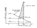
제3도는 제2도의 실시예의 밀폐공간의 압력 변화를 나타내는 지압선도(P-入선도).FIG. 3 is a chiropractic diagram (P-insert diagram) showing a change in pressure in the closed space of the embodiment of FIG. 2. FIG.
제4도는 다른 실시예를 나타낸 스크로울 랩의 맞물림 상태에 대한 횡 단면도.4 is a transverse cross-sectional view of an engaged state of a scowl wrap showing another embodiment.
제5도는 제4도의 실시예의 밀폐공간의 압력 변화를 나타내는 지압선도.FIG. 5 is a diagram of acupressure diagram showing the change in pressure in the closed space of the embodiment of FIG.
제6도는 또 다른 실시예를 나타내는 스크로울랩의 맞물림 상태에 대한 횡 단면도.Fig. 6 is a cross sectional view of an engaged state of a scrawl wrap showing another embodiment.
제7도는 제1도의 압축기를 헬륨 가스 압축용에 사용하는 다른 실시예를 나타내는 종 단면도.FIG. 7 is a longitudinal sectional view showing another embodiment in which the compressor of FIG. 1 is used for compressing helium gas. FIG.
제8도는 또 다른 실시예를 나타낸 것으로 밀폐형의 스크로울 유체기계의 종 단면도.8 is a cross-sectional view of another embodiment of a closed scroll fluid machine.
제9도는 제8도의 유체기계를 이용하는 냉동 장치의 구성도이다.9 is a block diagram of a refrigeration apparatus using the fluid machine of FIG.
* 도면의 주요부분에 대한 부호의 설명* Explanation of symbols for main parts of the drawings
1,51 : 고정스크로울부재 5,55 : 선회스크로울 부재1,51: Fixed scroll member 5,55: Slewing scroll member
6,56 : 프레임 8 : 오울덤(Oldham)기구6,56 Frame 8: Oldham Organization
16 : 전동기 21 : 밀폐공간16: electric motor 21: sealed space
32 : 오일분리기 46 : 전자 밸브32: oil separator 46: solenoid valve
47 : 조리개장치 50 : 밀폐용기47: aperture device 50: hermetically sealed container
58 : 자전 방지 부재 82 : 응축기58: anti-rotation member 82: condenser
85 : 증발기 86 : 오일냉각기85: evaporator 86: oil cooler
본 발명은 냉동, 공조용 등의 냉매 압축기, 극저온분야의 헬륨 냉동 장치 또는 공기 압축기용으로 사용되는 급유식 스크로울 유체기계에 관한 것이다.BACKGROUND OF THE INVENTION 1. Field of the Invention [0001] The present invention relates to a lubricated scroll fluid machine used for refrigerant compressors for refrigeration, air conditioning and the like, helium refrigeration apparatus for cryogenic applications, or air compressors.
스크로울 유체기계는 경판과 이 경판에 직립한 인벌류우트 또는 인벌류우트에 가까운 곡선으로 형성된 랩을 구비하고 있는 선회 스크로울 부재 및 경판의 중심부근에 배출구, 외측에 흡입구를 구비한 구조의 고정 스크로울 부재가 서로 랩을 내측으로 향하여 맞물림 되어 있다.The scrawl fluid machine is a rotating scrawl member having a hard disk and an involute or a wrap formed close to the involute which is upright on the hard disk, and a fixed outlet structure having an outlet port near the center of the hard disk and an inlet port on the outside The scrolling members are engaged with the wraps inward toward each other.
선회 스크로울 부재와 프레임 또는 고정 스크로울 부재와의 사이에 선회 스크로울 부재의 자전을 저지하는 오울덤 기구를 설치하고 선회 스크로울 부재에 회전축의 편심축부를 걸어맞추고 상기 편심축에 의한 선회 스크로울 부재를 자전시키지 않고 선회운동을 시켜 양 스크로울 부재에 의해 형성된 밀폐공간 내의 가스를 압축하여 압축가스를 배출구로 배출시킨다.An Owlham mechanism is provided between the swinging scroll member and the frame or the fixed scroll member to prevent rotation of the swinging scroll member, the eccentric shaft portion of the rotating shaft is engaged with the swinging scroll member, and the swinging scroll is rotated by the eccentric shaft. By rotating the member without rotating the member, the gas in the closed space formed by both scroll members is compressed to discharge the compressed gas to the outlet.
이 종류의 스크로울 유체기계는 예를 들면 미국특허 제3,884,599호의 명세서에 공개되어 있다.A scrawl fluid machine of this kind is disclosed, for example, in the specification of US Pat. No. 3,884,599.
이와 같은 구성의 스크로울 유체장치에서는 고정 스크로울 부재와 선회 스크로울 부재를 분리시키려는 힘이 밀폐공간의 압축과정의 가스의 압력에 의해 양 스크로울 부재에 작용한다. 양 스크로울 부재가 분리되면 압축가스는 저압측의 밀폐공간에 바이패스되며 압축성능은 저하된다. 그 이유는 선회 스크로울 부재의 경판의 배면에 가스압을 작용시켜 선회 스크로울에 축방향으로 억누르는 힘을 부여하며, 선회 스크로울 부재를 고정 스크로울 부재에 억누르고 있다. 일본국 특허공개공보소 제55-148,994호는 상기의 억누르는 힘을 선회 스크로울 부재의 경판의 배면에 흡입압력과 배출압력 사이의 압력을 유도하고, 이 중간압력으로 선회 스크로울 부재를 고정 스크로울 부재에 억누르는 축방향의 밀봉을 행한다.In the scroll fluid apparatus having such a configuration, a force for separating the fixed scroll member and the swinging scroll member is applied to both scroll members by the pressure of the gas during the compression process of the closed space. When the two scowl members are separated, the compressed gas is bypassed to the closed space on the low pressure side, and the compression performance is lowered. The reason for this is that gas pressure is applied to the back surface of the hard plate of the swinging scroll member to impart an axial pressure to the swinging scroll, and the swinging scroll member is pressed against the fixed scroll member. Japanese Laid-Open Patent Publication No. 55-148,994 induces a pressure between the suction pressure and the discharge pressure on the back surface of the hard disk of the swinging scroll member by applying the above-mentioned depressing force, and at this intermediate pressure, the fixed scroll member is fixed. The sealing in the axial direction pressed against the roll member is performed.
상기 구조의 스크로울 유체기계는 압축과정이 작동 가스의 냉각을 목적으로 양 스크로울 부재로 형성된 압축공간에 오일을 주입하고 압축중의 작동 가스의 냉각을 꾀하는 방식을 채용한 것이다.The scroll fluid machine of the above structure employs a method in which oil is injected into a compression space formed by both scroll members for the purpose of cooling the working gas and cooling of the working gas during compression.
상기 방식을 채용한 스크로울 유체기계는 일본국 실용신안공개소 제56-85,087호에 공개되어 있다.A scroll fluid machine employing the above method is disclosed in Japanese Utility Model Publication No. 56-85,087.
그런데 상기 방식으로는 압축기의 기동시 혹은 정지 직전 등에는 주입밀폐 공간에 오일이 충만하고 오일 압축을 일으키며, 스크로울 랩의 파손 사고를 초래할 우려가 있다. 또는 밀폐공간의 내부 압력이 이상하게 높아지므로 선회 스크로울 부재가 고정 스크로울 부재로 부터 분리되고, 압축 작용을 하지 않게 되며, 기종 불량의 현상을 나타내는 등의 문제점을 가진다.However, in the above method, when the compressor is started or just before stopping, the injection sealing space is filled with oil, causing oil compression, and there is a possibility of causing a breakage of the scrawl wrap. Alternatively, since the internal pressure of the closed space is abnormally high, the swinging scroll member is separated from the fixed scroll member, there is no compression action, and there is a problem such as indicating a bad model.
본 발명은 상기에 비추어 발명된 것으로서 오일압축의 방지와, 기동 불량 현상을 제거하는 것을 목적으로 한다.The present invention has been invented in view of the above, and its object is to prevent oil compression and to eliminate poor starting.
상기 목적을 달성하기 위하여 본 발명은 고정 스크로울 부재 또는 선회 스크로울 부재의 경판부에 양 스크로울 부재로 형성 되는 밀폐공간에 개구하는 오일 주입용 가는 구멍을 설치함과 동시에 상기 밀폐공간은 흡입실을 포함한 중간 압력실에 간헐적으로 연동하는 주입 오일이 빠져나갈 통로를 설치한 것을 특징으로 한다.In order to achieve the above object, the present invention provides a thin hole for oil injection opening in a closed space formed by both scroll members at the fixed plate member of the fixed scroll member or the swinging scroll member and at the same time the sealed space is a suction chamber. It characterized in that the passage installed in the intermediate pressure chamber, including the intermittent interlocking injection oil.
작동 가스의 냉각을 위해 밀폐공간에 주입된 오일은 기동시 혹은 정지시 등에는 상기 밀폐공간 사이에 충만 하지만, 상기 구성에 의하여 밀폐공간 내의 오일이 빠져나갈 통로를 거쳐 흡입실을 포함한 중간 압력실로 빠져나가기 쉽게 된다.The oil injected into the confined space for cooling the working gas is filled between the confined spaces at the time of starting or stopping, but is discharged into the intermediate pressure chamber including the suction chamber through the passage through which the oil in the confined spaces escapes. It is easy to leave.
따라서, 주입 오일이 밀폐공간에 충만하여 오일압축에 따른 밀폐 공간 내의 이상한 압력 상승은 방지되고, 오일 압축을 일으키는 일 없이 또 기동시의 동력 저감(기동 토오크의 저감)을 도모할 수 있어서 기동 불량을 일으키는 일도 없다.Therefore, the filling oil is filled in the sealed space and abnormal pressure rise in the sealed space due to the oil compression is prevented, and the starting power can be reduced and the starting torque can be reduced (starting torque reduction) without causing oil compression. It does not cause anything.
이하 본 발명의 실시예를 도면에 의거하여 설명한다.An embodiment of the present invention will be described below with reference to the drawings.
제1도는 크랭크축이 횡방향으로 늘어나는 횡형의 공기압축기를 나타낸다. 1은 고정 스크로울 부재이며, 경판부(1a)에 소용돌이형의 랩(1b)을 곧게 세우고, 그 중심부에 배출구(2), 외주부에 흡입구(3)를 구비하고 있다. 5는 선회 스크로울 부재이며, 경판(5a)에 소용돌이형의 랩(5b)을 곧게 세워져 형성되어 있다. 상기 고정 스크로울 부재(1)와 선회 스크로울 부재(5)는 서로 랩부를 내측을 향해 맞물리고 선회 스크로울 부재(5)는 고정 스크로울 부재(1)와 그 고정 스크로울(1)에 고정된 외부 프렘임(6)과의 사이에 수납되어 있다.1 shows a horizontal air compressor in which the crankshaft extends in the transverse direction. 1 is a fixed scroll member, and the helical wrap 1b is erected upright in the hard plate part 1a, and the
프레임(6)은 중앙부에 원통부(11)를 형성하고, 이 원통부(11)에 축받이(12),(13)가 형성되며, 회전축(7)이 지지되어 있다.The frame 6 forms the cylindrical part 11 in the center part, the
회전축(7)선단에는 편심추(7a)이 형성되고, 그 편심축(7a)에 선회 스크로울 부재(5)가 보스(5c)를 거쳐서 걸어맞추어져 있다. 또 외부 프레임(6)과 선회 스크로울 부재(5)와의 사이에는 오울덤 키이부와 링부 등을 가지는 오울덤 기구(8)를 구비하고, 선회 스크로울 부재(5)는 상기 편심축(7a)의 편심회전에 따라 자전하지 않고, 고정 스크로울 부재(1)에 대하여 선회 운동을 하도록 형성되있다.The eccentric weight 7a is formed in the front-end | tip of the rotating shaft 7, The turning scroll member 5 is engaged with the eccentric shaft 7a via the boss 5c. In addition, the outer frame 6 and the swinging scowl member 5 are provided with an Ouldham mechanism 8 having an Owldom key portion, a ring portion, and the like, and the swinging scowl member 5 has the eccentric shaft 7a. It is formed so that it does not rotate according to the eccentric rotation of and rotates with respect to the fixed scroll member 1.
회전축(7)에는 축받이(13)의 단부에 축봉함 장치(14)가 설치되고, 축단부는 축이은 곳(15)을 거쳐서 전동기(16)가 연결 되어 있다.The rotary shaft 7 is provided with a shaft sealing device 14 at the end of the bearing 13, the shaft end portion is connected to the
선회 스크로울 부재(5)의 상기 선회 운동에 따라, 양 스크로울 부재의 맞물림에 의하여 형성되는 밀폐공간(21)은 점차 중심으로 이동하여 용적이 감소된다. 가스는 흡입구(3)로 부터 흡입실(22)로 들어가고, 상기와 같이 압축되어서 배출구(2)로 부터 배출된다.According to the swinging motion of the swinging scroll member 5, the closed space 21 formed by the engagement of both scrolling members gradually moves to the center and the volume is reduced. The gas enters the
선회 스크로울 부재(5)의 경판(5a)의 배면부에는 그 선회 스크로울 부재(5)와 외부 프레임(6)으로서 배압실(23)이 형성되고, 이 배압실(23)과 압축 과정의 밀폐공간(21)과는 경판(1a)에 뚫어 설치된 가는 구멍(24a),(24b), 배관(25), 개구(26)를 거쳐서, 접속되며, 배압실(23)에는 압축과정에 있는 중간압력(흡입압과 배출압 사이의 압력)이 도입되며, 선회 스크로울 부재(5)를 고정 스크로울 부재(1)에 억누르는 축방향 부여력을 주고 있다.The back pressure chamber 23 is formed in the back part of the hard plate 5a of the turning scroll member 5 as the turning scroll member 5 and the outer frame 6, and the back pressure chamber 23 and the sealing process of the compression process are closed. The space 21 is connected to the space 21 through a thin hole 24a, 24b, a pipe 25, and an opening 26 provided in the plate 1a, and the back pressure chamber 23 has an intermediate pressure in the compression process. (Pressure between suction pressure and discharge pressure) is introduced to give an axial imparting force to hold the swinging scroll member 5 against the fixed scrolling member 1.
스크로울 유체기계의 작동 압축가스로서 공기 혹은 헬륨가스 등을 사용하였을 경우, 그 가스의 압축지수(단열지수)가 높기 때문에 배출구(2)로 부터 배출되는 배출가스 온도는 용이하게 300~500℃로서 고온이 된다.When air or helium gas is used as the operating compressed gas of the scowling fluid machine, since the compression index (insulation index) of the gas is high, the temperature of the exhaust gas discharged from the
따라서 작동가스의 냉각을 위해 오일을 압축과정의 밀폐공간에 주입하고, 작동가스를 냉각하는 방식이 실시되고 있다.Therefore, in order to cool the working gas, oil is injected into the closed space during the compression process, and a method of cooling the working gas is performed.
배축구(2)에 접속된 배출관(31)은 오일 분리기(32)에 접속되며, 그 분리기 내에는 분리판(33)이 설치되고 다른 측 상부에는 송출관(34)이 접소고되어 있다. 또 오일 분리기(32)의 저부에는 오일관(35)이 접속되며, 오일냉각기(36), 유량조절의 조리개장치(37)를 개재하고 오일 주입관(38a), (38b)으로 분기 접속되며, 또한 경판(1a)에 뚫어 설치된 오일 주입용 가는 구멍(39a), (39b)에 접속되고, 압축과정의 밀폐공간에 개구되어 있다.The discharge pipe 31 connected to the
도면중 실선 화살표는 작동가스의 흐름방향, 파선 화살표는 오일의 흐름 방향을 나타낸다.The solid arrows in the figure indicate the flow direction of the working gas, and the dashed arrows indicate the flow direction of the oil.
상기 가스압 도출 가는 구멍(24a), (24b) 및 오일 주입용 가는 구멍(39a), (39b)도 같은 압력관계에 있는 스크로울 랩의 측벽에 따른 대칭 위치에 한쌍씩 설치되어 있다.The gas pressure-derived fine holes 24a, 24b and oil injection
다음에 상기 가스압 도출용 가는구멍(24a), (24b) 및 오일 주입용 가는 구멍(39a), (39b)의 위치에 대하여 설명한다.Next, the positions of the gas pressure derivation fine holes 24a and 24b and the oil injection
제2도는 양쪽 스크로울 부재가 맞물림 상태의 횡 단면을 나타낸다.2 shows a transverse cross section in which both scroll members are engaged.
상기 가스압도출용 가는 구멍(24a), (24b)과, 오일 주입용 가는 구멍(39a), (39b)가 양 스크로울 부재로 형성 되는 밀폐공간(21a), (21b)을 거쳐서 간헐적으로 연결 할 수 있는 위치관계로 상기 가는 구멍이 뚫어 설치되어 있다.The gas pressure extraction thin holes 24a and 24b and the oil injection
즉 오일주입용 가는 구멍(39a), (39b)을 가스압 도출용 가는 구멍(24a), (24b)으로 부터 랩 감김끝을 향해(랩 외단을 향해)한번 감기 이내의 위치에 설치하면, 도시한 바와 같이 상기 가는 구멍(39a), (39b)과 (24a), (24b)는 간헐적으로 즉 선회 스크로울 부재의 1선회 중에는 꼭 한번은 밀폐공간을 거쳐 연통하도록 형성된다. 상기 위치 관계는 다음과 같이 표시된다.That is, when the oil injection
λb<λoin<λb+2π‥‥‥‥‥‥‥‥‥‥‥‥‥‥‥‥‥‥‥‥(1)λb <λoin <λb + 2π ‥‥‥‥‥‥‥‥‥‥‥‥‥‥‥‥‥‥‥‥ (1)
여기서 λoin : 오일 주입용 가는 구멍 위치의 스크로울 랩 감기 각도(rad)Where λoin is the scrawl wrap winding angle (rad) at the thin hole position for oil filling
λb : 가스압 도출용 가는 구멍 위치의 스크로울 랩 감기 각도(1rad)λb: Shroud lap winding angle (1rad) at the position of thin hole for deriving gas pressure
π : 원주율π: circumference
스크로울 랩 감기 각도란 스크로울 랩의 형태가 인벌류트 곡선인 경우, 그 곡선의 늘어나고 열리는 각을 의미한다. 제2도의 실시예에서 고정 스크로울 부재의 경판(1a)에 설치된 오일 주입용 가는 구멍(39a), (39b)의 위치는, λoin≒12.8rad이며, 가스압 도출용 가는 구멍(24a), (24b)의 위치는 λb≒8.8rad이다. 이 양자의 가는 구멍의 위치관계는 상기 (1)식을 만족하고, 오일 주입용 가는 구멍(39a), (39b)과 가스압 도출용 가는 구멍(24a), (24b)은 밀폐공간(21a), (21b)을 거쳐서 간헐적으로 연통된다.The throw wrap lap angle means the elongated and open angle of the curve if the form of the throw wrap is an involute curve. In the embodiment of FIG. 2, the positions of the oil injection
작동 가스의 냉각을 위해 밀폐공간에 주입된 오일은, 기동시 혹은 정지직전 등에는 밀폐공간에 충만하지만 상기 구조에 의해 이 오일이 상기 가스압 도출용 가는 구멍(24a), (24b)을 거쳐서 배압실(23)로 빠져나가기 쉬워진다.The oil injected into the closed space for cooling the working gas is filled in the closed space at the time of starting or just before stopping, but the oil is supplied to the back pressure chamber through the gas holes 24a and 24b for deriving the gas pressure. It becomes easy to escape to (23).
제3도는 스크로울 압축기의 기동초기의 지압선도(P-λ선도)를, 본 실시예의 경우(실선)와 오일이 빠져나가는 통로가 없는 종래의 경우(일점쇄선)을 비교하여 나타낸다. 또한 횡축은 용적(Ⅴ) 대신에 스크로울 랩 감기 각도(λ)로서 표시한다(도면중 λs는 스크로울 랩 감기 끝 각도를 나타낸다). 종래 기계의 경우는 비 압축성 오일을 압축하려고 하기 때문에, 도시한 바와 같이 스크로울 내부의 압력이 배출압력(Pd)을 크게 상회하는 듯한 이상한 오일압력(Pmax)이 작용하지만, 본 실시예의 경우는 가스압 도출용 가는 구멍(24a), (24b)이 밀폐 공간(21a), (21b)과 간헐적으로 연통되어 있기 때문에 상기 유압력(Pmax)보다도 압력 레벨이 낮은 배압실(23) 쪽으로 오일이 이동하고, 밀폐공간(21a), (21b)의 압력은 저하된다. 당연한 것이지만 배압실(23)의 압력(Pb)은 오일압력(Pmax)에 대하여 Pb<<Pmax의 관계로 된다.FIG. 3 shows the acupressure diagram (P-λ diagram) of the initial stage of the start of the scroll compressor in comparison with the case of the present embodiment (solid line) and the conventional case without a passage through which oil escapes (single-dotted line). In addition, the abscissa is represented by the scroll wrap wrap angle (lambda) instead of the volume (V) (lambda s in the drawing represents the scroll wrap wrap end angle). In the case of the conventional machine, since the compressor is trying to compress the non-compressible oil, as shown in the drawing, a strange oil pressure Pmax in which the pressure inside the scroll seems to greatly exceed the discharge pressure Pd works, but in the case of this embodiment, the gas pressure Since the fine holes 24a and 24b for derivation are in intermittent communication with the sealed
지압선도로 포위된 면적은 압축기의 소용동력에 비례하므로 본 실시예의 의하면 오일 압축에 따르는 밀폐 공간 내의 이상한 압력상승이 방지되므로 기동 순간의 동력 저감(기동 토오크의 저감)을 도모할 수가 있다.Since the area surrounded by the acupressure diagram is proportional to the utility power of the compressor, according to the present embodiment, an abnormal pressure rise in the sealed space due to oil compression is prevented, so that power reduction at the instant of starting (reduction of starting torque) can be achieved.
상기 실시예에 있어서 가스압 도출용 가는 구멍(24a), (24b)은 고정 스크로울의 경판(1a)에 설치하였으나, 선회 스크로울의 경판(5a)의 대응위치에 뚫어 설치하여도 전적으로 동등하다.In the above embodiment, the gas holes for deriving the gas pressures 24a and 24b are provided in the rigid plate 1a of the fixed scroll, but they are completely equivalent even if they are drilled in the corresponding positions of the rigid plate 5a of the rotating scroll.
상기 실시예는 가스압 도출용 가는 구멍(24a), (24b)과 오일 주입용 가는 구멍(39a), (39b)을 서로 압력적으로 대칭한 위치로 한쌍씩 설치하고 있으나, 실용적으로는, 가스압도출용 가는 구멍과 오일 주입용 가는 구멍을 각각 1개씩 설치하여도 동일한 작용 효과를 나타낸다.In the above embodiment, the gas pressure deriving fine holes 24a and 24b and the oil injection
또 가스압 도출용 가는 구멍(24a), (24b)의 구멍지름은 실용상 랩(1b), (5b)의 두께보다 작은 값으로 설정하는 것이 바람직하다.In addition, it is preferable to set the hole diameters of the gas holes for deriving the gas pressure 24a and 24b to a value smaller than the thickness of the wraps 1b and 5b for practical use.
제4도는 다른 실시예를 나타내고, 스크로울 랩의 맞물림 상태의 횡단면도를 나타낸다.4 shows another embodiment and shows a cross-sectional view of the engaged state of the scrawl wrap.
이 실시예는 오일 주입용 가는 구멍(41a), (41b)을 스크로울 랩의 감기 종단부로 부터 한번 감기 이내의 고정 스크로울 부재의 경판의 랩측벽에 따른 위치에 뚫어 설치하므로써, 오일을 주입한 밀폐공간이 흡입실에 연통하는 랩 공간과 간헐적으로 연통하도록 형성된 것이다. 즉, 오일 주입용 가는 구멍의 위치는 다음식으로 나타난다.In this embodiment, the oil is injected by drilling the oil holes fine holes 41a and 41b in a position along the lap side wall of the hard plate of the fixed scroll member within one winding from the winding end of the scroll wrap. The sealed space is formed to intermittently communicate with the wrap space communicating with the suction chamber. That is, the position of the thin hole for oil injection is represented by the following equation.
λoin>λe-2π‥‥‥‥‥‥‥‥‥‥‥‥‥‥‥‥‥‥‥‥‥‥‥‥(2)λoin> λe-2π ‥‥‥‥‥‥‥‥‥‥‥‥‥‥‥‥‥‥‥‥‥‥‥‥‥‥‥‥‥‥‥‥
여기서 λei : 스크로울 랩 감기 끝 각도Where λei: scrawl wrap winding end angle
λoin : 오일 주입용 가는 구멍 위치의 스크로울 랩의 감기 각도(red)λoin: winding angle of the scrawl wrap at the fine hole position for oil filling (red)
π : 원주율π: circumference
도면에 있어서 오일 주입용 가는 구멍(41a), (41b)은 고정 스크로울의 경판(1a)의 스크로울 랩(1b)의 감기 종단부(1j), (1j')로 부터 스크로울 랩의 감기 시작(중앙부)을 향해 한번 감기 보다 적은 우치(도면에 있어서는 약 0.9감기)에 살치되어 있다.In the drawing, the thin holes 41a and 41b for oil injection are wound around the wrap wrap from the winding end portions 1j and 1j 'of the scroll wrap 1b of the fixed plate 1a of the fixed scroll. It is pretended to be less cold (about 0.9 cold in the drawing) than a single winding towards the start (center).
상기구조에 의하여 밀폐공간에 주입되는 오일은 간헐적으로 흡입공간에 주입되며, 밀폐공간(21a), (21b)에 주입되는 주입 유량은 감소되고, 밀폐공간(21a), (21b)에서의 오일 압축을 피할 수가 있다.The oil injected into the sealed space by the above structure is intermittently injected into the suction space, and the injection flow rate injected into the sealed
또한 상기 오일 주입용 가는 구멍(41a), (41b)이 개구 되는 흡입공간에 간헐적으로 연통하는 공간은 흡입하여 폐쇄전의 흡입과정의 공간에도 간헐적이 되고, 선회 스크로울의 선회 운동에 따라 물론 압축실로 되는 공간이다.In addition, the space intermittently communicating with the suction space in which the oil injection thin holes 41a and 41b are opened becomes intermittent in the suction process space before closing, and, of course, into the compression chamber according to the swinging movement of the turning scroll. It is a space.
상기(2)식에 있어서, 실용적으로는 오일 주입용 가는 구멍(41a) (41b)은 λoin≒λs-2π+(![]()
![]()
![]()
![]()
의 위치가 바람직하다고 생각된다.The position of is considered to be preferable.
제5도는 흡입 과정시에서의 스크로울의 내부압력 변화를 나타낸 P-λ선도를 나타낸다. 도면중의 λm는 제4도에 나타낸 흡입 과정 완료 위치(1m), (1m')에서의 스크로울 랩 감기 각도를 나타낸다. 따라서 흡입 과정시에 있어서의 오일 주입기간, 환언하면 흡입실과 연통하는 공간과 오일 주입용 가는 구멍(41a), (41b)이 연통하는 기간은 제5도에 의하여, 스크로울 랩 감기 각도로 표현하면, 다음식으로 나타난 접촉구간이 된다.5 shows a P-λ diagram showing the change in the internal pressure of the scowl during the suction process. [Lambda] m in the figure indicates the scroll wrap winding angle at the suction process completion positions 1m and 1m 'shown in FIG. Therefore, the oil injection period during the suction process, in other words, the period in which the space communicating with the suction chamber and the oil holes fine holes 41a and 41b communicate with each other is expressed by a scroll wrap winding angle as shown in FIG. This results in a contact section given by
△λ=λoin-λm‥‥‥‥‥‥‥‥‥‥‥‥‥‥‥‥‥‥‥‥‥‥‥(4)Δλ = λ oin-λm ‥‥‥‥‥‥‥‥‥‥‥‥‥‥‥‥‥‥‥‥‥‥‥
여기서 △λ : 흡입 과정시에서의 오일 주입 구간으로 되는 스크로울 랩 감기 각도 상의 접촉범위(rad)Λλ where the contact range on the claw wrap winding angle to be the oil filling section during the suction process
λoin : 오일 주입용 가는 구멍(55)의 위치에 있어서의 스크로울 랩 감기 각도(rad)λ oin: Scrow lap winding angle (rad) at the position of the
λm : 흡입과정 완료순간의 양 스크로울의 접촉점(1m), (1m')의 위치에서의 스크로울 랩 감기 각도(rad).λm: The throw lap winding angle (rad) at the position of the contact points (1m) and (1m ') of both scrolls at the completion of the suction process.
상기 (3) (4)식과 비교해 보았을 경우, 상기△λ는 △λ=(![]()
![]()
![]()
![]()
실용적으로 가는 구멍(41a), (41b)이 흡입하여 폐쇄전의 흡입 공간에 연통하는 기간은 주축의 1회전 중에 대하여 약 30도에서 45도의 회전 각도의 범위라고 생각된다.The period in which the thinner holes 41a and 41b are practically inhaled and communicate with the suction space before closing is considered to be in the range of a rotation angle of about 30 degrees to 45 degrees with respect to one rotation of the main shaft.
상기와 같이 오일 주입용 가는 구멍(41a), (41b)을 흡입 폐쇄전의 흡입 공간에 간헐적으로 연통하는 위치에 설치 하므로써, 주입 오일에 따라 흡입 과정시의 작동 가스의 냉각 작용을 가져올 수가 있으므로 상술한 오일 압축의 방지 외에 정상 운전시의 성능향상(체적효율의 향상의)작용효과도 가진다.As described above, since the oil holes thin holes 41a and 41b are intermittently connected to the suction space before the suction closing, the cooling oil of the working gas during the suction process can be brought about depending on the injected oil. In addition to the prevention of oil compression, it also has the effect of improving performance (of improving volumetric efficiency) during normal operation.
상기 냉각 작용은 다음 이유에 따른다. 제4도에 있어서 작동 가스의 흡입가스 온도(Ts)는 통상 Ts≒20~30°이며, 흡입실(22)에 이르면 주위의 열적 영향을 받아 작동 가스의 온도는 상승된다. 개방형 스크로울 압축기의 경우에는 상기 내부 과열량은 약 20°~30℃까지 미치므로, 흡입실(22) 내의 작동 가스 온도(흡입실 가스 온도) Tso≒50℃ 정도가 된다. 즉 실제로 양 스크로울에 흡입되기 직전의 가스 온도는 상기의 Tso 값으로 된다.The cooling action is based on the following reason. In FIG. 4, the intake gas temperature Ts of the working gas is usually Ts # 20 to 30 °, and when the
한편 오일 주입용 가는 구멍(41a), (41b)으로 부터 주입되는 오일의 온도(급유온도) Toil는 수냉식의 오일 냉각기(도시없음)를 사용하였을 경우, 상기 급유온도 Toil≒20℃ 전후이며, 공냉식의 오일 냉각기(도시없음)를 사용하였을 경우에는 Toil≒45℃ 정도로 설정된다. 이와 같이 어느 경우라도 흡입실 가스 온도(Tso)보다도 급유온도(Toil)를 낮게 유지할 수가 있으므로 주입 오일에 따라 흡입 가정시의 작동 가스의 가스의 냉각 작용이 행하여 진다.On the other hand, the oil temperature (lubrication temperature) of the oil injected from the oil holes (41a) and (41b) for oil injection, when a water-cooled oil cooler (not shown) is used, the oil supply temperature is about 20 ° C, and is air-cooled. When oil cooler (not shown) is used, Toil is set at about 45 ° C. In this case, since the oil supply temperature Toil can be kept lower than the intake chamber gas temperature Tso, the cooling operation of the gas of the working gas at the time of intake household is performed depending on the injected oil.
제6도는 또 다른 실시예를 나타내며, 오일 주입용 가는 구멍과, 가스압도출용 가는 구멍의 위치 관계를 상술의 제2도와 제4도의 실시예를 조합시킨 위치에 설정한 실시예에 상당하는 것이다.FIG. 6 shows another embodiment, which corresponds to an embodiment in which the positional relationship between the oil hole fine hole and the gas pressure extraction fine hole is set at a position where the above-described embodiment of FIG. 2 and FIG. 4 are combined.
고정 스크로울 혹은 스크로울의 경판(1a), (5a)에 뚫어 설치하는 오일 주입용 가는 구멍(42a), (42b)과 가스압 도출용 가는 구멍(43a), (43b)을 다음의 위치 관계에 설치한다.The oil injection fine holes 42a, 42b and the gas pressure derivation
λb+2π>λoin>λe-2π‥‥‥‥‥‥‥‥‥‥‥‥‥‥‥‥‥‥‥‥‥(5)λb + 2π> λoin> λe-2π ‥‥‥‥‥‥‥‥‥‥‥‥‥‥‥‥‥‥‥‥‥ 5
여기서 λb : 가스압 도출용 가는 구멍(43a), (43b) 위치에서의 스크로울 랩 감기 각도(rad)Where λb is the scroll wrap winding angle (rad) at the
λoin : 오일 주입용 가는 구멍(42a), (42b)의 위치에서의 스크로울 랩 감기 각도(rad)λ oin: Scrow lap winding angle (rad) at the positions of fine holes 42a and 42b for oil injection
λe : 스크로울 랩 감기 종 단에서의 스크로울 랩 감기 각도(rad)λe: Shroud wrap winding angle (rad) at the end of the scrawl wrap winding
즉, 오일 주입용 가는 구멍(42a), (42b)을 스크로울 랩의 감기 종단으로 부터 한번 감기 이내의 랩의 따른 위치에 뚫어 설치함과 동시에 가스압 도출용 가는 구멍(43a), (43b)을 오일 주입용 가는 구멍(42a), (42b)의 위치에서 랩의 감기 시작(내측)을 향해 한번 감기 이내의 랩에 따른 위치에 뚫어 설치한다.That is, the oil injection fine holes 42a and 42b are drilled and installed at the position along the wrap within one winding from the winding end of the scrawl wrap, and the
가는 구멍을 상기 위치관계에 구성하므로서 밀폐공간에 오일을 주입하는 오일 주입용 가는 구멍(42a), (42b)은 흡입 폐쇄전의 작동 공간에 간헐적으로 연통함과 동시에 그 가는 구멍(42a), (42b)은 밀폐공간을 거쳐 가스압도출용 가는 구멍(43a), (43b)과 간헐적으로 연통할 수가 있다.The oil injection fine holes 42a and 42b for injecting oil into the sealed space by configuring the fine holes in the positional relationship intermittently communicate with the working space before the suction closing and at the same time, the fine holes 42a and 42b. ) Can intermittently communicate with the
상기와 같이 주입 오일이 흡입 폐쇄전의 작동 공간에 간헐적으로 주입되므로서 흡입 과정시의 작동 가스의 냉각 작용을 행함과 동시에 기동시 혹은 정지 직전 등에는 밀폐공간에 충만되는 주입 오일이 간헐적으로 배압실로 빠짐으로 오일 압축은 방지된다.As described above, the injection oil is intermittently injected into the working space before the intake closing, thereby cooling the working gas during the intake process and at the same time, the filling oil filled in the closed space intermittently falls into the back pressure chamber during starting or just before stopping. Oil compression is prevented.
도시한 바에 의거하여 상기 가는 구멍(42a), (42b), (43a), (43b)의 위치 관계의 구체적인 수치는Based on the illustration, the specific numerical value of the positional relationship of the said
λe : 24.50 radλe: 24.50 rad
λoin : 18.55 rad‥‥‥‥‥‥‥‥‥‥‥‥‥‥‥‥‥‥‥‥‥‥(6)λoin: 18.55 rad ‥‥‥‥‥‥‥‥‥‥‥‥‥‥‥‥‥‥‥‥‥‥‥ 6
λb : 14.00 radλb: 14.00 rad
로 되며 상기(5)식을 만족하고 있다.It satisfies the above formula (5).
제7도는 스크로울 유체기계를 헬륨 가스 압축용에 사용하는 실시예를 나타낸다.7 shows an embodiment using a scowl fluid machine for helium gas compression.
압축기의 구조 및 오일 주입용 가는 구멍(44a), (44b) 및 가스압 도출용 가는 구멍(48a), (48b) 등은 상기 각 실시예와 전적으로 동일하게 형성된다.The structure of the compressor, the fine holes 44a and 44b for oil injection, the fine holes 48a and 48b for deriving gas pressure, and the like are formed in the same manner as in the above embodiments.
이 종류의 압축기의 기동직후는 헬륨 및 압축기 전체의 온도가 낮으므로, 주입 하는 오일량은 압축기의 정상 상태에 비하여 적은량으로 된다.Since the temperature of the helium and the whole compressor is low immediately after the start of this kind of compressor, the amount of oil to be injected becomes smaller than the normal state of the compressor.
이 때문에 본 실시예는 오일 주입용 가는 구멍(44a), (44b)에 접속되는 외부 오일 배관(45)에는 전자 밸브(46)를 설치하고, 전자 밸브(46)를 여는 타이밍을 압축기의 기동시 보다도 늦축게 하는 조작회로(도시안됨)로 한다. 이에 따라서 기동초기의 양 스크로울 내부에 고이는 주입 오일량을 최대한 적게할 수가 있다. 도면중 47은 조리개 장치를 나타낸다. 도면중 실선 화살표는 작동 가스의 흐름방향, 파선 화살표는 오일의 흐름 방향을 나타낸다.For this reason, in this embodiment, the solenoid valve 46 is provided in the external oil piping 45 connected to the oil holes fine holes 44a and 44b, and the timing which opens the solenoid valve 46 is made when the compressor starts. A slower operation circuit (not shown) is used. Accordingly, the amount of injected oil accumulated in both scrolls of the initial start can be minimized. 47 shows an aperture device. The solid arrow in the figure indicates the flow direction of the working gas, and the broken arrow indicates the flow direction of the oil.
상기 각 실시예의 오일 주입용 가는 구멍 및 가스압도출용 가는 구멍은 고정 스크로울의 경판 또는 스크로울의 경판의 어느 곳에 뚫어 설치하여도 동등한 효과가 있으나, 특히 가스압도출용 가는 구멍을 고정 스크로울의 경판에 설치한 실시예에서는 그 가는 구멍의 가공성을 향상시키는 효과가 있다.The oil injection fine hole and the gas pressure extraction fine hole of each embodiment have the same effect even if it is installed in any of the hard plate of the fixed scowl or the hard plate of the scowl, in particular, the thin plate for gas pressure extraction thin plate of the fixed scowl In the embodiment provided in the present invention, there is an effect of improving the workability of the thin hole.
즉 선회 스크로울의 경판 배면에는 선회 보스(제1도의 5C 참조)가 설치되어 있고, 가스압도출용 가는 구멍을 선회 스크로울 측에 설치할 경우는 상기 보스의 존재에 따라 그 보스를 피하여 가스압도출용 가는 구멍을 비스듬히 뚫어 설치하여야 할 경우가 있어 가공성이 나쁘지만, 고정 스크로울의 경판에서는 경판에 직교하여 구멍을 뚫을 수 있기 때문에 가공성은 향상된다.That is, the turning boss (refer to 5C of FIG. 1) is provided on the back surface of the turning scowl. The workability is poor because it may be necessary to install the hole at an angle, but the workability is improved in the hardboard of the fixed scroll because the hole can be drilled perpendicular to the hardboard.
제8도는 또 다른 실시예를 나타내고, 스크로울 유체기례를 밀폐용기에 수납한 냉동, 공조용의 밀폐형 스크로울 유체기계의 종 단면도를 나타낸다.8 shows another embodiment, and shows a longitudinal cross-sectional view of a hermetic scull fluid machine for refrigeration and air conditioning in which a scowl fluid example is housed in a hermetically sealed container.
밀폐용기(50)는 케이싱부(50a), 상부실(50b), 하부실(50c)로서 형성되며, 그 용기 내에는 윗쪽에 스크로울 압축기부를, 그 아랫쪽에 전동기부를 일체로 연설한 장치가 수납되어 있다. 그 압축기부는 압축요소부인 고정 스크로울 부재(51)와 선회 스크로울 부재(55)의 양 스크로울 부재와 선회 스크로울(55)의 자전을 저지하는 자전 방지 부재(58) 및 주축(57)을 지지하는 3개의 축받이부, 즉 선회 축받이 (61)와 주축받이(62) 및 보조 축받이(63)와 주추(57)의 하부에 배설 되어 있는 정동기(59), 고정 스크로울(51)을 고정하는 프레임(56)등으로서 형성된다.The
상기 고정 스크로울 부재(51) 및 선회 스크로울 부재(55)는 제1도의 실시예의 양 부재와 동일하게 형성되며, 스크로울 랩의 외주부의 흡입실에는 흡입관(64)이 고정 스크로울 부재에 축방향으로 세워 설치되고, 흡입관(64)에는 역지(逆止) 밸브(65)가 배설되어 있다. 고정 스크로울 부재의 중앙부의 배출구(66)는 밀폐용기(50) 내에 개구하고, 밀폐용기(50) 내에는 배출압력의 분위기로 유지되어 있다.The fixed scroll member 51 and the swinging
선회 스크로울 부재(55)의 경판의 배면부에는 프레임(56)에 배압실(67)이 형성되어 있다. 이 배합실(67)에 중간적 가스압을 도입하기 위해 선회 스크로울의 경판에 뚫어 설치되는 가스압 도출용 가는 구멍(68a), (68b) 및 압축실에 오일을 주입하기 위해 고정 스크로울 부재의 경판에 뚫어 설치되는 오일 주입용 가는 구멍(69a), (69b)은 제2도와 동일한 위치관계로 설치된다. 저온저압의 냉매 가스는 흡입관(64)으로 부터 역지 밸브(65)를 거쳐서 흡입구(70)에 유입되고, 선회 스크로울 부재의 선회 운동에 따라 흡입 폐쇄후, 그 밀폐공간은 점차 중심으로 이동하고, 용적을 감소하고 그 밀폐공간 내의 작동가스는 압축되어서 배출구(66)에서 밀폐용기 내의 상부 배출실(71)로 배출된다.The
이 배출 가스는 통로(72a), (72b)를 거쳐 전동기(59) 주위의 전동기실(73)로 도입되고, 이어서 배출관(74)으로 부터 기외(機外)로 도출된다.The discharge gas is introduced into the electric motor chamber 73 around the
상기의 배출가스 중에는 오일이 포함되어 있고, 전동기실(73)로 유입된 오일을 포함한 배출 가스는 넓은 용적의 전도기실에서 유속이 감소되어 오일 입자의 자중에 따른 오일 분리 작용이 행하여지며, 그 전동기실(73)에서 냉매가스와 오일로 분리된다. 가스중에서 분리된 오일은 밀폐용기 저부에 고이게 된다. 이 고인 오일은 양유관(揚油管)(75) 및 주축내의 급유구멍(76)을 거쳐 압력차로서 각 축받이로 급유되고, 각 축받이를 윤활한 오일은 배압실(67)로 누설된다. 도면중 실선 화살표는 작동가스의 유통방향, 파선 화살표는 오일의 흐름방향을 나타낸다.The exhaust gas includes oil, and the exhaust gas including the oil introduced into the electric motor chamber 73 reduces the flow rate in a large volume of the electric conduction chamber so that an oil separation action is performed according to the self-weight of the oil particles. In the chamber 73, refrigerant gas and oil are separated. Oil separated in the gas accumulates at the bottom of the sealed container. This accumulated oil is lubricated to each bearing as a pressure difference through the
또 상기 저유 오일의 일부는 오일 송출관(77)을 거쳐 압력차로서 기외로 송출되고, 후술하는 오일 주입에 공급된다.A part of the low oil oil is sent out of the air as a pressure difference via the
배압실(67)에는 가스압 도출용 가는 구멍(68a), (68b)을 거쳐 압축과정의 밀폐 공간내의 중간 가스압이 도입되고, 그 가스압으로서 선회 스크로울 부재를 고정 스크로울 부재를 고정 스크로울 부재에 억누르는 축방향 부여력을 얻고있다.The intermediate gas pressure in the closed space of the compression process is introduced into the
오일 주입용 가는 구멍(69a), (69b)에는 배관(78a), (78b)이 접속되고, 배관(78a), (78b)을 거쳐 공급된 오일은, 상기 가는 구멍(69a), (69b)를 거쳐서 밀폐공간으로 주입되며, 압축과정의 냉매 가스의 냉각을 한다.
제2도의 실시예로서 상세히 설명한 바와 같이 밀폐공간을 거쳐서 가스압도출용 가는 구멍(68a), (68b)과 간헐적으로 연통하므로, 주입 오일의 일부는 배압실(67)에 간헐적으로 유입되고, 배압실(67)의 냉각 기능도 가진다.As described in detail as the embodiment of FIG. 2, since the gas intermittently communicates with the
또 기동시 혹은 정지 직전등에 압축실에 충만한 오일은 가스압 도출용 가는 구멍(68a), (68b)을 거쳐서 간헐적으로 배압실(67)로 빠져나가기 때문에 오일 압축현상은 저감 제거된다.In addition, the oil filling phenomenon in the compression chamber at the time of starting or just before stopping is intermittently exited into the
제9도는 제8도의 압축기를 조입한 냉매회로를 나타낸다. 압축기(81)의 배출관(74)은 응축기(82)로 접속되고, 이어서 배관(83)에서 팽창 밸브(84)를 개재하여 증발기(85)에 접속되며, 이어서 오일 냉각기(86)를 거쳐 흡입관(64)으로 접속된다.9 shows a refrigerant circuit in which the compressor of FIG. 8 is incorporated. The discharge pipe 74 of the
압축기 저부의 오일 송출관(77)은 유량 조절 밸브(87)를 거쳐 상기 오일 냉각기(86)에 접속되고, 오일 냉각(86)의 다른 축으로 부터는 오일 배관(78)을 거쳐 오일 주입용 배관(78a), (78b)에 접속된다. 오일 송출관(77)의 오일은 고온, 고압상태이며, 유량 조절밸브(87)로서 감압됨과 동시에 유량이 조절된다. 감압된 오일은 오일 냉각기(86)에서 흡입냉매 가스로서 냉각되며, 오일 배관(78), 오일 주입용 배관(78a), (78b)을 거쳐 압축실로 주입된다. 이 오일의 흐름은 밀폐용기 내의 고압 압력과 오일 주입 밀폐공간의 압력과의 차압에 의하여 행하여진다. 또한 유량 조절밸브(87)를 오일 냉각기(86)의 상류측에 배치하므로서 오일 냉각기(86)는 하류측인 압력, 즉 오일 주입용 압력의 분위기로 된다. 따라서 오일 냉각(86)의 내부 압력은 저압측으로 되기 때문에 소형 경량화를 도모할 수가 있다.The
Claims (7)
Applications Claiming Priority (2)
| Application Number | Priority Date | Filing Date | Title |
|---|---|---|---|
| JP59104514A JPH0631625B2 (en) | 1984-05-25 | 1984-05-25 | Scroll fluid machinery |
| JP59-104514 | 1984-05-25 |
Publications (2)
| Publication Number | Publication Date |
|---|---|
| KR850008707A KR850008707A (en) | 1985-12-21 |
| KR880000550B1 true KR880000550B1 (en) | 1988-04-13 |
Family
ID=14382599
Family Applications (1)
| Application Number | Title | Priority Date | Filing Date |
|---|---|---|---|
| KR1019850003498A KR880000550B1 (en) | 1984-05-25 | 1985-05-22 | Scroll compressor |
Country Status (4)
| Country | Link |
|---|---|
| US (1) | US4648814A (en) |
| JP (1) | JPH0631625B2 (en) |
| KR (1) | KR880000550B1 (en) |
| DE (1) | DE3518639A1 (en) |
Families Citing this family (35)
| Publication number | Priority date | Publication date | Assignee | Title |
|---|---|---|---|---|
| JPS61169686A (en) * | 1985-01-23 | 1986-07-31 | Hitachi Ltd | Scroll compressor |
| JPH0617676B2 (en) * | 1985-02-15 | 1994-03-09 | 株式会社日立製作所 | Helium scroll compressor |
| JPH0455274Y2 (en) * | 1986-02-17 | 1992-12-25 | ||
| JPS62253993A (en) * | 1986-03-24 | 1987-11-05 | Daikin Ind Ltd | Scroll type fluid machine |
| US5649816A (en) * | 1986-08-22 | 1997-07-22 | Copeland Corporation | Hermetic compressor with heat shield |
| US4877382A (en) * | 1986-08-22 | 1989-10-31 | Copeland Corporation | Scroll-type machine with axially compliant mounting |
| US5219281A (en) * | 1986-08-22 | 1993-06-15 | Copeland Corporation | Fluid compressor with liquid separating baffle overlying the inlet port |
| JPH06100185B2 (en) * | 1987-07-10 | 1994-12-12 | 株式会社日立製作所 | Scroll compressor |
| KR950008694B1 (en) * | 1987-12-28 | 1995-08-04 | 마쯔시다덴기산교 가부시기가이샤 | Scroll type compressor |
| JP2696791B2 (en) * | 1989-02-10 | 1998-01-14 | 三菱電機株式会社 | Scroll compressor |
| JP2618501B2 (en) * | 1989-10-30 | 1997-06-11 | 株式会社日立製作所 | Low-temperature scroll type refrigerator |
| DE69202399T2 (en) * | 1991-06-13 | 1995-10-19 | Daikin Ind Ltd | Flow machine in spiral construction. |
| US5224357A (en) * | 1991-07-05 | 1993-07-06 | United States Power Corporation | Modular tube bundle heat exchanger and geothermal heat pump system |
| JPH09196478A (en) * | 1996-01-23 | 1997-07-31 | Nippon Soken Inc | Refrigerating cycle |
| US6129531A (en) * | 1997-12-22 | 2000-10-10 | Copeland Corporation | Open drive scroll machine |
| JP2000352377A (en) * | 1999-06-08 | 2000-12-19 | Mitsubishi Heavy Ind Ltd | Open type compressor |
| US6505475B1 (en) | 1999-08-20 | 2003-01-14 | Hudson Technologies Inc. | Method and apparatus for measuring and improving efficiency in refrigeration systems |
| US6315536B1 (en) | 1999-11-18 | 2001-11-13 | Copeland Corporation | Suction inlet screen and funnel for a compressor |
| US7047753B2 (en) * | 2000-03-14 | 2006-05-23 | Hussmann Corporation | Refrigeration system and method of operating the same |
| US7000422B2 (en) * | 2000-03-14 | 2006-02-21 | Hussmann Corporation | Refrigeration system and method of configuring the same |
| US6332327B1 (en) * | 2000-03-14 | 2001-12-25 | Hussmann Corporation | Distributed intelligence control for commercial refrigeration |
| US6647735B2 (en) * | 2000-03-14 | 2003-11-18 | Hussmann Corporation | Distributed intelligence control for commercial refrigeration |
| US6999996B2 (en) * | 2000-03-14 | 2006-02-14 | Hussmann Corporation | Communication network and method of communicating data on the same |
| US20040016253A1 (en) * | 2000-03-14 | 2004-01-29 | Hussmann Corporation | Refrigeration system and method of operating the same |
| US6973794B2 (en) | 2000-03-14 | 2005-12-13 | Hussmann Corporation | Refrigeration system and method of operating the same |
| JP2002106484A (en) * | 2000-09-29 | 2002-04-10 | Toyota Industries Corp | Motor type scroll compressor |
| JP4376554B2 (en) * | 2003-06-12 | 2009-12-02 | パナソニック株式会社 | Scroll compressor |
| JP4192158B2 (en) * | 2005-03-24 | 2008-12-03 | 日立アプライアンス株式会社 | Hermetic scroll compressor and refrigeration air conditioner |
| US7841845B2 (en) * | 2005-05-16 | 2010-11-30 | Emerson Climate Technologies, Inc. | Open drive scroll machine |
| WO2008096445A1 (en) * | 2007-02-09 | 2008-08-14 | Mitsubishi Heavy Industries, Ltd. | Scroll compressor and air conditioner |
| JP6035111B2 (en) * | 2012-10-31 | 2016-11-30 | ジョンソンコントロールズ ヒタチ エア コンディショニング テクノロジー(ホンコン)リミテッド | Helium hermetic scroll compressor |
| JP6416559B2 (en) * | 2014-09-11 | 2018-10-31 | 日立ジョンソンコントロールズ空調株式会社 | Scroll compressor and air conditioner |
| US9850903B2 (en) * | 2014-12-09 | 2017-12-26 | Emerson Climate Technologies, Inc. | Capacity modulated scroll compressor |
| JP1574165S (en) * | 2016-08-31 | 2020-04-06 | ||
| JP1574166S (en) | 2016-08-31 | 2020-04-06 |
Family Cites Families (8)
| Publication number | Priority date | Publication date | Assignee | Title |
|---|---|---|---|---|
| US3884599A (en) * | 1973-06-11 | 1975-05-20 | Little Inc A | Scroll-type positive fluid displacement apparatus |
| JPS53119412A (en) * | 1977-03-28 | 1978-10-18 | Hitachi Ltd | Scroll compressor |
| US4314796A (en) * | 1978-09-04 | 1982-02-09 | Sankyo Electric Company Limited | Scroll-type compressor with thrust bearing lubricating and bypass means |
| JPS55148994A (en) * | 1979-05-09 | 1980-11-19 | Hitachi Ltd | Closed scroll fluid device |
| JPS5685087U (en) * | 1979-12-05 | 1981-07-08 | ||
| JPS578386A (en) * | 1980-06-16 | 1982-01-16 | Hitachi Ltd | Hermetic scroll compressor |
| JPS58170876A (en) * | 1982-03-31 | 1983-10-07 | Toshiba Corp | Scroll compressor |
| JPS5993987A (en) * | 1982-11-19 | 1984-05-30 | Hitachi Ltd | Scroll fluid machine |
-
1984
- 1984-05-25 JP JP59104514A patent/JPH0631625B2/en not_active Expired - Lifetime
-
1985
- 1985-05-08 US US06/731,913 patent/US4648814A/en not_active Expired - Lifetime
- 1985-05-22 KR KR1019850003498A patent/KR880000550B1/en not_active IP Right Cessation
- 1985-05-23 DE DE19853518639 patent/DE3518639A1/en active Granted
Also Published As
| Publication number | Publication date |
|---|---|
| JPS60249683A (en) | 1985-12-10 |
| DE3518639C2 (en) | 1989-08-17 |
| KR850008707A (en) | 1985-12-21 |
| JPH0631625B2 (en) | 1994-04-27 |
| DE3518639A1 (en) | 1985-11-28 |
| US4648814A (en) | 1987-03-10 |
Similar Documents
| Publication | Publication Date | Title |
|---|---|---|
| KR880000550B1 (en) | Scroll compressor | |
| KR880002907Y1 (en) | Scroll-type compressor | |
| KR100274612B1 (en) | Scroll Gas Compressor | |
| US4560330A (en) | Scroll device with suction chamber pressure relief | |
| US4216661A (en) | Scroll compressor with means for end plate bias and cooled gas return to sealed compressor spaces | |
| KR930008349B1 (en) | Scroll compressor | |
| KR20030062208A (en) | Scroll compressor with vapor injection | |
| JPH0617676B2 (en) | Helium scroll compressor | |
| JP2008101559A (en) | Scroll compressor and refrigeration cycle using the same | |
| JP3028054B2 (en) | Scroll gas compressor | |
| JPH0772548B2 (en) | Hermetic scroll compressor | |
| JP3774964B2 (en) | Scroll compressor | |
| KR100517929B1 (en) | Apparatus preventing high temperature for scroll compressor | |
| JP2533732B2 (en) | Refrigeration equipment using scroll fluid machinery | |
| JP4529118B2 (en) | Scroll compressor for helium | |
| JPH0526035B2 (en) | ||
| JP4222857B2 (en) | Refrigeration equipment | |
| JP2956555B2 (en) | Scroll gas compressor | |
| JP3252495B2 (en) | Scroll compressor | |
| JP3255441B2 (en) | Control device of heat pump air conditioner using scroll compressor | |
| JPH06294388A (en) | Scroll compressing device | |
| JPH08210288A (en) | Scroll fluid machine | |
| JP3635826B2 (en) | Scroll compressor | |
| JPH0742952B2 (en) | Lubrication type hermetic scroll compressor | |
| JP3096531B2 (en) | Scroll compressor |
Legal Events
| Date | Code | Title | Description |
|---|---|---|---|
| A201 | Request for examination | ||
| G160 | Decision to publish patent application | ||
| E701 | Decision to grant or registration of patent right | ||
| GRNT | Written decision to grant | ||
| FPAY | Annual fee payment |
Payment date: 20050404 Year of fee payment: 18 |
|
| EXPY | Expiration of term |