KR880000396B1 - Tracking control system - Google Patents
Tracking control system Download PDFInfo
- Publication number
- KR880000396B1 KR880000396B1 KR8200660A KR820000660A KR880000396B1 KR 880000396 B1 KR880000396 B1 KR 880000396B1 KR 8200660 A KR8200660 A KR 8200660A KR 820000660 A KR820000660 A KR 820000660A KR 880000396 B1 KR880000396 B1 KR 880000396B1
- Authority
- KR
- South Korea
- Prior art keywords
- track
- head
- tracking control
- rotating
- signal
- Prior art date
Links
Images


Classifications
-
- G—PHYSICS
- G11—INFORMATION STORAGE
- G11B—INFORMATION STORAGE BASED ON RELATIVE MOVEMENT BETWEEN RECORD CARRIER AND TRANSDUCER
- G11B5/00—Recording by magnetisation or demagnetisation of a record carrier; Reproducing by magnetic means; Record carriers therefor
- G11B5/48—Disposition or mounting of heads or head supports relative to record carriers ; arrangements of heads, e.g. for scanning the record carrier to increase the relative speed
- G11B5/58—Disposition or mounting of heads or head supports relative to record carriers ; arrangements of heads, e.g. for scanning the record carrier to increase the relative speed with provision for moving the head for the purpose of maintaining alignment of the head relative to the record carrier during transducing operation, e.g. to compensate for surface irregularities of the latter or for track following
- G11B5/584—Disposition or mounting of heads or head supports relative to record carriers ; arrangements of heads, e.g. for scanning the record carrier to increase the relative speed with provision for moving the head for the purpose of maintaining alignment of the head relative to the record carrier during transducing operation, e.g. to compensate for surface irregularities of the latter or for track following for track following on tapes
- G11B5/588—Disposition or mounting of heads or head supports relative to record carriers ; arrangements of heads, e.g. for scanning the record carrier to increase the relative speed with provision for moving the head for the purpose of maintaining alignment of the head relative to the record carrier during transducing operation, e.g. to compensate for surface irregularities of the latter or for track following for track following on tapes by controlling the position of the rotating heads
Abstract
Description
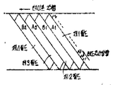
제1도는 종래 방식의 헤드주사 궤적의 일예를 도시한 도면.1 is a diagram showing an example of a conventional head scan trajectory.
제2도는 본 발명 방식의 일실시예가 적용된 트래킹 제어시스템을 적용한 블록 계통도.2 is a block diagram of a tracking control system to which an embodiment of the present invention is applied.
제3도는 방위각(azimuth) 기록방식에 의한 자기테이프 상의 트랙패턴의 일예를 도시한 도면.3 is a diagram showing an example of a track pattern on a magnetic tape by an azimuth recording method.
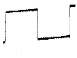
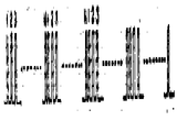
제4도는 제4a도 내지 제4c도는 제각기 제2도의 작동 설명을 위한 신호 파형도.4 is a signal waveform diagram for explaining the operation of FIG. 4A to FIG. 4C, respectively, FIG.
제5도는 본 발명 방식의 샘플점의 위치 일예를 도시한 드럼 평면도.5 is a drum plan view showing an example of the position of the sample point of the present invention scheme.
제6(a)도 내지 제6(c)도는 제각기 본 발명 방식에 의한 헤드주사 궤적의 제각기 예를 도시한 도면.6 (a) to 6 (c) each show an example of a head scan trajectory according to the present invention.
제7도는 영상 트랙과 재생궤적을 도시한 도면.7 is a view showing an image track and a playback trajectory.
제8도는 헤드 이동기구를 도시한 도면.8 shows a head moving mechanism.
* 도면의 주요부분에 대한 부호의 설명* Explanation of symbols for main parts of the drawings
1 : 기록 트랙 3 : 재생 FM 영상신호 입력단자1: Record track 3: Playback FM video signal input terminal
4 : 드럼 펄스 입력단자 5 : 포락선 검출기4 drum
6 : 샘플회로 7 : 펄스 선택기6: Sample Circuit 7: Pulse Selector
8 : 시스템 콘트롤 9, 11 : 메모리8: System control 9, 11: Memory
12 : 트래킹 신호 발생회로 13 : 가산기12: tracking signal generating circuit 13: adder
14 : 헤드 기구 앰프 15 : 헤드 이동기구14: head mechanism amplifier 15: head moving mechanism
16 : 회전드럼 17, 18 : 회전헤드16: rotating drum 17, 18: rotating head
본 발명은 트래킹 제어 방식에 관한 것이고 재생시의 회전헤드의 주사해야할 트랙에 대한 트랙 어긋나기를 정확하게 검출하여 트래킹 제어하는 방식을 제공하는 것을 목적으로 한다.The present invention relates to a tracking control method, and an object of the present invention is to provide a method for accurately detecting and tracking a track deviation of a track to be scanned by a rotating head during reproduction.
나선 주사형 회전헤드 자기 기록재생장치(이하 VTR라함)에서는 드럼으로 형성되어 있는 테이프 안내용홈의 산란, 테이프 주행계의 풀의 경사나 높이의 산란, 또는 고정드럼의 부착장소나 각도의 산란 등 테이프 주행계의 기구의 산란에 의하여 비디오 트랙의 만곡이 필연적으로 생긴다. 이 때문에 기록시의 VTR과는 다른 VTR로 재생하는 경우의 호환 재생시에 있어서는 최량의 트래킹 상태가 얻어지지 않는다. 특히 저비용화 때문에 테이프 주행계가 간략화되어 있는 가정용 VTR에서는 기록재생밀도의 고밀도화와 더불어 소요가 높은 트래킹 정밀도를 확보하면서 재생하는 것은 극히 곤란하다. 또 기록을 하였을때 VTR와 재생을 하는 VTR와의 사이에서 회전헤드가 자기테이프에 닿기 시작하는 위치부터 제어헤드까지의 거리가 상위하는 경우도 있고 이 경우에는 최량의 트래킹 상태가 얻어지지 않고 재생신호의 SN비가 나쁘게 된다.In a spiral scanning rotary head magnetic recording and reproducing apparatus (hereinafter referred to as a VTR), scattering of tape guide grooves formed by drums, inclination or height of the pool of the tape traveling system, scattering of fixed places and angles, etc. Scattering of the video track inevitably occurs due to scattering of the mechanism of the tape running system. For this reason, the best tracking state is not obtained at the time of compatible playback when playing back a VTR different from the VTR at the time of recording. In particular, in the home VTR, which has a simplified tape traveling system due to the low cost, it is extremely difficult to reproduce while ensuring high density of recording and reproduction density and high tracking accuracy. In addition, the distance between the control head and the position where the rotating head starts to reach the magnetic tape may be different between the VTR and the reproducing VTR when recording. In this case, the best tracking state is not obtained and SN ratio becomes bad.
그래서 종래 트래킹 노부를 조정하여 재생제어신호를 소요시간 지연시켜서 정상의 트래킹을 해하고 있었지만 이것은 1개의 트랙의 길이 방향에 대하여 평행으로 헤드주사 기적을 움직이게 하는 제어를 하는 것 뿐이고 1개의 트랙의 만곡에 정확히 주종 주사시키게 제어하는 것은 불가능하였다.Therefore, the conventional tracking furnace was adjusted to delay the regeneration control signal by the required time to perform normal tracking. However, this is only a control for moving the head scanning miracle in parallel with respect to the length direction of one track. It was not possible to control exactly the injection of the master.
이 때문에 보다 정밀도의 높은 트래킹 제어를 하기 위해서는 기록트랙의 길이 방향에 대하여 직각의 방향(트랙폭의 방향)상으로 헤드 이동기구에 의하여 회전헤드를 변위시켜서 트랙어긋나기를 보정하는 필요가 있다.For this reason, for more accurate tracking control, it is necessary to correct the track shift by displacing the rotating head by the head moving mechanism in the direction perpendicular to the longitudinal direction of the recording track (track width direction).
종래 이 트래킹 제어에 있어서의 트랙 어긋나기의 검출방법에는 서로 주파수가 다른 파이롯 신호를 주요정보 신호에 중첩하여 기록하고 재생시에 주사하여야할 트랙의 양측의 트랙부터 각각 밸브별 재생한 2종류의 파이롯 신호의 상대적 레벨차부터 트랙어긋나기 방향 및 트랙어긋나기량을 검출하는 방식이 있었지만 이것은 바이트 방해가 생기든지 또 기록재생되어야 할 주용정보 신호의 대역을 제한하는 것으로서 바람직하지 못하였다.Conventionally, in the tracking control method of tracking control, two types of pies reproduced by valves starting from tracks on both sides of the track to be scanned are superimposed on the main information signal by superimposing pilot signals having different frequencies. There has been a method of detecting the track shift direction and the track shift amount from the relative level difference of the lot signal, but this is not preferable as it restricts the band of the main information signal to be recorded and reproduced or the byte disturbance occurs.
한편 기록 트랙이 파이롯 신호를 기록하지 않고 트랙 어긋나기의 검출을 하는 방식으로서 종래 데이저(워브링) 방식이 있었다. 이 방식은 회전드럼에 동기한 주기가 짧은 주파수의 정현파로 회전헤드를 트랙폭 방향상 변위시켜서 제1도에 표시한 바와같이 기록트랙 1에 대하여 회전헤드의 상단이 2a, 하단이 2b로 각각 표시하는 정현파상의 주사궤적을 그리게 하여 이 주사궤적 중의 상린하는 정의 피이크점과 부의 피이크점과에 있어서의 FM 재생신호 레벨의차를 검출하는 것에 의하여 트랙어긋나기를 검출하는 것이었다.On the other hand, there has been a conventional data ring method in which the recording track detects the track shift without recording the pilot signal. In this method, the sine wave with a short frequency synchronized with the rotating drum is displaced in the track width direction so that the top of the rotating head is 2a and the bottom is 2b for the
그런데 이 종래의 데이저 방식은 하나의 트랙어긋나기 검출을 위해서는 회전헤드가 위에 어긋난 점과 아래로 어긋난 점이 필요하였다. 그러나 이 상하의 검출점이 정현파형 주사궤적 2a, 2b의 상과 하의 피이크점이므로 장소적으로 다른것에 의한 트랙어긋나기 검출에 오차가 생기다는 결점이 있었다. 또 자기 테이프가 아지마스 기록 방식으로 기록되어 있던 경우에는 회전헤드를 트랙폭 방향상으로 요동시키면 재생신호중에 시간축 변동이 생겨 이것이 재생화면에 만곡이나 반점으로 되어 나타난다는 결점이 있었다. 또 데이저 주파수를 높이 할수록 이 어긋나기 정보량이 증가하지만 동시에 상기 시간축 변동이 더욱 증가한다는 결점이 있었다.By the way, this conventional data system requires the point where the rotation head is shifted up and the point is shifted down in order to detect one track shift. However, since the upper and lower detection points are the peak points of the upper and lower
본 발명은 상기의 결점을 제거하는 것으로서 제2도 이하와 같이 그 일 실시예에 대하여 설명한다. 본 발명은 그 헤드 나선 주사 방식에 대한 것이다. 제2도는 본 발명 방식의 일 실시예가 적용된 트래킹 제어계의 블록계통도를 표시한다.The present invention removes the above-mentioned drawbacks and the second embodiment will be described as follows. The present invention relates to a head spiral scanning method. 2 shows a block diagram of a tracking control system to which an embodiment of the present invention is applied.
동도중 3은 입력단자로 주파수 변조된 영상신호가 예를들면 서로 아지마스각이 다른 2개의 회전헤드에 의하여 교대로 제3도중 A, B, A2, B2…로 표시하는 트랙을 순자형성하여 기록된 자기테이프를 기록시와 같이 아지마스각의 회전헤드에 의하여 재생하여 얻은 재생 FM 영상 신호가 들어온다. 여기서 제3도중 1개의 트랙은 1필드의 FM 영상 신호가 기록되어 있다. 4는 입력단자로 회전헤드의 회전에 동기한 예를들면 회전드럼 1회전당 1주기의 제4(a)도에서와 같이 대칭구형파와 같은 드럼펄스가 입력된다. 이런 드럼펄스는 펄스선택기 7에 입력되며, 펄스 선택기 7은 이러한 드럼펄스에 의하여 제4(c)도에 되시한 바와같은 셈플링 펄스는 생성하여, 셈플회로 6에 공급된다. 이러한 셈플링펄스는 제5도에 도시된바와 같이 회전드럼 16위로 180°대향관위치에 설치된 회전드럼 17 및 18이 자기 테이프와 접하는 기간중에서 1 내지 N으로서 제각기 도시된 위치를 과하여, 제각기 펄스셀렉터 7에서 출력된다.In the figure, 3 denotes a video signal frequency-modulated by the input terminal, for example, by two rotating heads having different azimas angles, respectively, A, B, A 2 , B 2 . A reproduction FM video signal obtained by reproducing the magnetic tape recorded by net-shaping the track indicated by the " In one track of FIG. 3, an FM video signal of one field is recorded. 4 denotes an input terminal in which drum pulses such as symmetrical square waves are input, for example, as shown in FIG. 4 (a) of one cycle per rotation of a rotating drum. This drum pulse is input to the pulse selector 7, and the pulse selector 7 generates a sampling pulse as shown in FIG. 4 (c) by this drum pulse, and is supplied to the
한편, 입력단자 3에 입력되는 재생 FM 영상신호는 포락선 검출기 5에 공급되며, 여기서 포락선 검파된 후에 셈플회로 6에 공급된다.On the other hand, the reproduction FM video signal input to the input terminal 3 is supplied to the
셈플회로 6은 펄스선택기 7에서의 셈플링펄스에 의해 1개의 기록 트랙의 N개소의 재생 FM 영상신호레벨을 셈플하고, 순차 취출되어 메모리 9에 인가된다. 메모리 9는 이러한 레벨을 기억한다. 한편 펄스선택기 7은 상기 드럼펄스는 1/2하향계수하여, 제4(b)도에 도시된 바와 같이 2필드(1프레임) 주기의 헤드 요동신호를 발생하며, 이것을 가산회로 13, 구동앰프 14를 제각기 통하혀 헤드 이동기구 15에 공급한다. 제4(b)도에 도시된 헤드 요동신호가 하이레벨의 주기(1프레임)는 회전 헤드 17, 18은 헤드 이동기구 15에 의하여, 기준의 높은 위치보다 높은 제1의 높은 위치로 재생되며, 헤드 요동신호가 로우레벨의 기간(1프레임), 회전헤드 17, 18은 헤드 이동기구 15에 의해 기준의 높은 위치보다 낮은 제2의 높은 위치에서 재생된다.The
따라서, 예를들어 회전헤드 17, 18이 제각기 정규의 위치에 있을 때에(즉 트랙은 0)는 회전헤드 17은 제1필드 재생시에 제6(a)도의 17a, 에 의하여, 기록트랙 1보다 약간 상방을 주사하면, 다음에 제2필드 재생시에도 동일하게 18a2로서 도시된 바와같이 회전헤드 18이 트랙 1보다 약간 위를 주사한다. 그래서 다음의 제3필드 재생시에는 회전헤드 17이 동일도면 (A)의 17a3로서 표시된 바와같이, 기록 트랙 1보다도 약간 하방을 주사하며, 따라서 제4필드 재생시에도 동일하게 18a4로서 도시된 것보다 조금 아래를 주사한다.Thus, for example, when the rotating heads 17 and 18 are in their respective normal positions (ie, the track is 0), the rotating head 17 is slightly smaller than the
이하에서 상기 동작이 반복된다. 또한, 도시의 편의상 트랙은 1개로서 도시되었으나, 제각기 프레임은 다른 트랙에 기록되어질 수 있음은 제3도의 설명을 통하여 알 수 있다.The above operation is repeated below. In addition, although the track is shown as one for convenience of illustration, it can be seen from the description of FIG. 3 that each frame can be recorded on another track.
한편, 회전헤드 17, 18이 상방으로 되어 있을 때에는 제6(b)도에 도시된 주사 궤적을 나타내며, 또한 하방에 있는 경우에는 동도(C)에 도시된 주사궤적을 나타낸다.On the other hand, when the rotary heads 17 and 18 are upward, the scanning trajectory shown in FIG. 6 (b) is shown, and when the rotary heads 17 and 18 are below, the scanning trajectory shown in the same diagram C is shown.
또한, 제6(b)도, 제6(c)도중에, 17b1, 17c1은 회전헤드 17의 제1피일드 재생위치, 17b3, 17c3는 회전헤드 17의 제3피일드 재생위치, 18b4, 18c4는 회전헤드 18의 제4피일드 재생위치를 도시한다.In addition, in Fig. 6 (b) and Fig. 6 (c), 17b 1 and 17c 1 are the first feed regeneration positions of the rotary head 17, 17b 3 and 17c 3 are the third feed regeneration positions of the rotary head 17, 18b 4 , 18c 4 show the fourth feed regeneration position of the rotating head 18.
그런데, VTR에서는 동시에 정규 트랙에 대하여 상하 2개의 주사궤적을 얻을 수 없다. 또 2헤드 VTR의 경우에는, 동일 채널의 헤드가 재생하는 트랙에 관하여서는 최저 10개는 전혀 동일한 트랙으로 하여도 불편이 없다. 따라서 상기와 같은 1프레임 단위로서 회전 헤드 17, 18을 트랙폭방향 상하로 이동하므로서 4필드 구간에서 2개의 헤드의 1트랙 사이에서는 트래킹정보를 얻고, 이때의 FM 영상신호 레벨을 비교하므로서 트랙오차의 방향을 검출하여도 문제가 없다.In the VTR, however, two scanning trajectories cannot be obtained at the same time for the normal track. In the case of the two-head VTR, at least ten tracks of the same tracks reproduced by the head of the same channel may be the same tracks. Therefore, by moving the rotating heads 17 and 18 up and down in the track width direction in one frame unit as described above, tracking information is obtained between one track of two heads in four field sections, and the level of the track error is compared by comparing the FM video signal levels. There is no problem even if the direction is detected.
여기에서의 검출결과를 기본으로한 제어에서는 즉, 제2도에 도시된 메모리 9에 예를들어 상항방향으로 어긋나게 회전헤드 17, 18에 의한 제1, 제2필드의 재생 FM 영상신호의 제각기 N개의 샘플링 데이타가 기록된다. 그 다음의 제3필드, 제4필드의 재생시에는 회전헤드 17, 18은 하향방향으로 어긋나게되어, 상기 동일모양으로 메모리 9에 제각기 N개의 샘프링데이타가 기억된다.In the control based on the detection result here, i.e., each of the reproduction FM video signals of the first and second fields of the first and second fields by the rotation heads 17 and 18, for example, shifted upward in the memory 9 shown in FIG. Sampling data is recorded. In the subsequent regeneration of the third and fourth fields, the rotating heads 17 and 18 are shifted in the downward direction, and N sampling data are stored in the memory 9 in the same shape.
다음에, 전압비교기 10에 있어서는, 제3필드의 샘플링 데이타와 제1피일드의 샘플링 데이타가 비교되며 제4필드의 샘플링 데이타와 제2필드의 샘플링 데이타가 비교된다. 전압비교기 10의 출력신호는 메모리 11에 트랙마다 검출신호로서 되고 메모리 11에 기옥되어진후 트래킹 신호 발생회로 12에 공급되며, 회전헤드 17, 18의 제각기 주사위치에 대응하는 트랙오차 보정용 트래킹신호로 변환되어진 후에, 가산회로13에 공급되며, 상기 펄스분리기 7에서의 제4(b)도에 도시된 헤드 요동신호가 가산된다. 가산회로 13의 출력가산회로는 구동램프 14를 통하여 헤드 이동기구 15에 인가되며, 헤드 주사궤적이 제6(a)도에 1점점선 또는 점선으로 도시된 바와같이 제어된다. 이상의 동작은 시스템콘트롤 8의 제어하에 작동된다.Next, in the voltage comparator 10, the sampling data of the third field and the sampling data of the first feed are compared, and the sampling data of the fourth field and the sampling data of the second field are compared. The output signal of the voltage comparator 10 is used as a detection signal for each track in the memory 11, and is stored in the memory 11 and supplied to the tracking signal generation circuit 12, and converted into a tracking error correction signal corresponding to the respective dice of the rotary heads 17 and 18. After that, it is supplied to the
이것에 의하여 본 실시예에서는 1프레임 단위로서 회전헤드를 트랙폭방향위에서 상하이동(요동)하고, 상방향에서 어긋나게 주사될 때에 주사신호를 1개의 기록 트랙상의 N개의 샘플점으로서 샘플링하여 얻어지는 데이타를 메모리하고, 이러한 데이타와 하향방향으로 헤드를 어긋나게 주사하여 얻은 재생신호의 N개의 샘플링 데이타를 비교하여 트랙오차를 검출하게 되므로, 종래의 디져(dizzer) 방식에 의하여 방위각 기록된 자기테이프 재생시에 생기는 재생화면의 만곡이나 색수차를 해소할 수 있게된다. 또한 샘플점은 헤드를 상하로 어긋나게 하는 경우, 동일한 장소에서는 트랙오차의 검출에 오차가 없게된다.As a result, in the present embodiment, data obtained by sampling the scan signal as N sample points on one recording track when the rotating head is moved (swinged) in the track width direction in one frame unit and shifted in the upward direction is scanned. Reproducing the memory tape when the azimuth-recorded magnetic tape is reproduced by a conventional dizzer method because the memory is detected and the track error is detected by comparing the data with the N sampling data of the reproduction signal obtained by scanning the head in a downward direction. The curvature and chromatic aberration of the screen can be eliminated. In addition, when the sample point shifts the head up and down, there is no error in the detection of the track error at the same place.
다음에 프레임마다에 재생패턴이 다른 경우의 제어를 생각하자. 제7도는 영상트랙과 재생궤적을 도시한 것으로서, 이러한 구동에 의하여, 정지, 보통, 2배속도, 3배속도 재생에 있어서 프레임마다의 재생궤적은 동등하다. 더우기 1/2속도 재생시에는 2프레임 즉, 4트랙에 있어서도 1필드분의 주사를 행한다. 따라서, 1/2속도 재생패턴에 있어서, 본 방식의 자동트레킹 제어를 행하는 경우, 8트랙마다, 회전헤드의 상하조작이 행하여져 트랙오차를 검출한다. 동일하게 1/3속도 재생패턴은 6트랙에 걸쳐서 보통 재생시의 1필드분의 조작을 하므로서, 12트랙으로서 회전헤드의 상하 반복을 행한다. 일반적으로 N프레임(2N트랙)에 걸쳐서 1필드분의 주사를 행한다. 경우에는 4N 트랙마다 회전헤드의 상하 반복을 행하여 트랙오차를 검출한다.Next, consider the control when the playback pattern is different for each frame. Fig. 7 shows the image track and the reproduction trajectory, and by this driving, the reproduction trajectories for each frame are equal in still, normal, double speed and triple speed reproduction. In addition, during 1 / 2-speed reproduction, one field is scanned even for two frames, that is, four tracks. Therefore, in the 1 / 2-speed reproducing pattern, when the automatic tracking control of this system is performed, the up and down operation of the rotating head is performed every eight tracks to detect the track error. Similarly, the 1 / 3-speed reproducing pattern repeats the rotation head up and down as 12 tracks while operating one field for normal reproduction over 6 tracks. In general, one field is scanned over N frames (2 N tracks). In this case, the track error is detected by repeating the rotation head up and down every 4N tracks.
헤드 이동기구 15로서는 제8도에 보인바와 같이 서로 굴곡방향을 달리하는 압전 세라믹스의 판이 도전성 가요판(可僥板)을 거쳐서 접착하여 되는 주지의 굴곡형 바이몰프를 써서 그 일단을 고정하여 타단의 자유단부에 회전헤드를 취부하고 그 인가전압의 극성 및 전압치에 의해서 압전 새라믹스의 판의 일방이 신장되고 타방이 축소하는 것에 의해 트랙 장축방향에 대하여 직각의 방향으로 회전헤드를 변위시키도록한 것을 사용할 수 있다. 또, 회전드람과 일체적으로 회전 시킬 수 있는 회종기체의 서로 대향하는 각 선단부에 회전 헤드를 각각 합계 2개를 취부하여, 회동기체(回動基體)를 그 중심부를 지지하는 지점부재를 지점으로 하여 트랙킹 제어전력에 응해서 회동드럼의 회전면과 격교하는 평면상에 시이소오 동작시키는 방식이라도 좋다.As the head moving mechanism 15, as shown in FIG. 8, one end of the other end is fixed by using a well-known bent bimorph, in which the plates of piezoelectric ceramics having different bending directions are bonded through a conductive flexible plate. The rotating head is mounted at the free end, and one side of the plate of the piezoelectric ceramic is extended and the other side is reduced by the polarity and voltage value of the applied voltage so as to displace the rotating head in a direction perpendicular to the track long axis direction. Can be used. In addition, a total of two rotating heads are attached to each of the front end portions of the rotating gas which can be rotated integrally with the rotating drum, and the point member for supporting the center of the rotating gas is used as the point. Thus, the system may be operated on a plane intersecting with the rotating surface of the rotating drum in response to the tracking control power.
상술과 같이 본 발명으로 되는 트랙킹 제어방식은 2헤드 헤리칼스캔형 자기 재생장치로서 헤드 이동기구에 의해 자기테이프상의 기록트랙의 장축방향에 대하여 직각 방향상으로 회전헤드를 변위시켜서 변위되는 회전헤드의 재생신호 레벨에 의해 트랙차이를 검출하고 그 검출출력에 의해 트랙킹제어를 하는 트랙킹제어 방식에 있어서 상기 회전헤드가 N후 레임분의 트랙에 따라서 주사하고 1후레임분의 신호로서 재생할때에 2N 후레임분의 트랙주사를 단위로하여 트랙킹제어 하도록한 때문에 종래의 디셔 방식에서 보여지는 아지마스 기록된 자기테프의 재생시의 시간축 변동에 의한 화면굴곡이나 색얼룩을 제거할 수 있으며 또 파이롯트 신호를 기록하고 있지 않으므로 기록재생신호 대역에 제한을 부여하거나 또 비드방해를 가지게 하는 염려가 없고 또 1개의 트랙의 샘플수 N은 헤드 요동신호의 주파수에 의하지 않기 때문에 정보량을 소망의 양만큼 증가할 수 있으며 또 이 샘플점은 각 트랙에 있어서 같은 장소이기 때문에 트랙벗어남 검출에 생기는 에러의 발생을 제거할 수가 있으며 또 테프 속도가 가변속이라해도 통상속도와 다르지 않는 상기의 효과가 얻어지는 등의 특징을 가지는 것이다.As described above, the tracking control method according to the present invention is a two-head helical scan type magnetic reproducing apparatus which reproduces a rotating head displaced by displacing the rotating head in a direction perpendicular to the major axis direction of a recording track on a magnetic tape by a head moving mechanism. In a tracking control method that detects a track difference by signal level and performs tracking control by its detection output, when the rotating head scans the track after N frames and reproduces it as a signal for one frame, Tracking control by track scan unit eliminates screen distortion and color spots caused by time-base fluctuations during playback of azimas recorded magnetic tapes, which are seen in conventional dishers. There is no fear of limiting the reproduction signal band or causing bead obstruction. Since the number of samples N of one track does not depend on the frequency of the head rocking signal, the amount of information can be increased by a desired amount, and since this sample point is the same place in each track, the occurrence of an error in track off detection can be avoided. Even if the tape speed is a variable speed, the above-mentioned effect which is not different from the normal speed can be obtained.
Claims (1)
Applications Claiming Priority (3)
| Application Number | Priority Date | Filing Date | Title |
|---|---|---|---|
| JP19689 | 1981-02-13 | ||
| JP56019689A JPS57135425A (en) | 1981-02-13 | 1981-02-13 | Tracking control system |
| JP56-19689 | 1981-02-13 |
Publications (2)
| Publication Number | Publication Date |
|---|---|
| KR830009563A KR830009563A (en) | 1983-12-22 |
| KR880000396B1 true KR880000396B1 (en) | 1988-03-21 |
Family
ID=12006205
Family Applications (1)
| Application Number | Title | Priority Date | Filing Date |
|---|---|---|---|
| KR8200660A KR880000396B1 (en) | 1981-02-13 | 1982-02-13 | Tracking control system |
Country Status (2)
| Country | Link |
|---|---|
| JP (1) | JPS57135425A (en) |
| KR (1) | KR880000396B1 (en) |
Families Citing this family (1)
| Publication number | Priority date | Publication date | Assignee | Title |
|---|---|---|---|---|
| JPS6242681A (en) * | 1985-08-20 | 1987-02-24 | Matsushita Electric Ind Co Ltd | Tracking control method for magnetic recording and reproducing device |
-
1981
- 1981-02-13 JP JP56019689A patent/JPS57135425A/en active Granted
-
1982
- 1982-02-13 KR KR8200660A patent/KR880000396B1/en active
Also Published As
| Publication number | Publication date |
|---|---|
| JPS57135425A (en) | 1982-08-21 |
| KR830009563A (en) | 1983-12-22 |
| JPS6321966B2 (en) | 1988-05-10 |
Similar Documents
| Publication | Publication Date | Title |
|---|---|---|
| US4897739A (en) | Multi-channel recording apparatus using a plurality of heads in turn | |
| CA1094681A (en) | Tracking control apparatus | |
| US4148083A (en) | Reproducing system having scanning transducer means which are selectively deflectable to avoid tracking errors | |
| KR0169712B1 (en) | Dynamic head position tracking control for a magnetic tape playback system | |
| US4402022A (en) | Tracking control system in a magnetic reproducing apparatus | |
| US4426666A (en) | Video signal recording/reproducing apparatus | |
| KR0159499B1 (en) | Automatic head position tracking system for video signals recorded in a segmented format | |
| US4482928A (en) | Tracking control system for magnetic recording and reproducing system | |
| US4246616A (en) | System for reproducing a video signal in a slow motion or still picture reproduction | |
| US4433350A (en) | Tracking error detection system in a magnetic reproducing apparatus | |
| US4268876A (en) | Magnetic reproducing device | |
| US4438465A (en) | Tracking control system for an information signal recording and reproducing apparatus | |
| US4418366A (en) | Head control and signal selector for playback at high-speed of helical scan video tape | |
| US4470079A (en) | Tracking control system in a magnetic recording and reproducing apparatus | |
| KR880000396B1 (en) | Tracking control system | |
| EP0030469B1 (en) | Video tape recorder including tracking apparatus | |
| US4432026A (en) | Apparatus and method for determining read head position | |
| KR880000323B1 (en) | Tracking system at magnetic reproducing apparatus | |
| ATE18312T1 (en) | DEVICE FOR PLAYING VIDEO SIGNALS. | |
| JPS613302A (en) | Automatic tracking device | |
| JP3271248B2 (en) | Tracking control device for signal recording / reproducing device | |
| JPS6321970B2 (en) | ||
| JPS6321972B2 (en) | ||
| JPS6321978B2 (en) | ||
| JPS6321968B2 (en) |