KR870000801B1 - Remotely installed,operated and removed manipulator for steam generator - Google Patents
Remotely installed,operated and removed manipulator for steam generator Download PDFInfo
- Publication number
- KR870000801B1 KR870000801B1 KR1019840006279A KR840006279A KR870000801B1 KR 870000801 B1 KR870000801 B1 KR 870000801B1 KR 1019840006279 A KR1019840006279 A KR 1019840006279A KR 840006279 A KR840006279 A KR 840006279A KR 870000801 B1 KR870000801 B1 KR 870000801B1
- Authority
- KR
- South Korea
- Prior art keywords
- steam generator
- master
- arm
- head
- mast
- Prior art date
Links
Images


Classifications
-
- F—MECHANICAL ENGINEERING; LIGHTING; HEATING; WEAPONS; BLASTING
- F22—STEAM GENERATION
- F22B—METHODS OF STEAM GENERATION; STEAM BOILERS
- F22B37/00—Component parts or details of steam boilers
- F22B37/002—Component parts or details of steam boilers specially adapted for nuclear steam generators, e.g. maintenance, repairing or inspecting equipment not otherwise provided for
- F22B37/003—Maintenance, repairing or inspecting equipment positioned in or via the headers
- F22B37/005—Positioning apparatus specially adapted therefor
-
- B—PERFORMING OPERATIONS; TRANSPORTING
- B25—HAND TOOLS; PORTABLE POWER-DRIVEN TOOLS; MANIPULATORS
- B25J—MANIPULATORS; CHAMBERS PROVIDED WITH MANIPULATION DEVICES
- B25J9/00—Programme-controlled manipulators
Abstract
Description
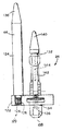
제1도는 본 발명장치가 재순환증기발생기에 설치된 상태의 부분단면도.1 is a partial cross-sectional view of the apparatus of the present invention installed in the recycle steam generator.
제2도는 재순환증기발생기에 설치된 본 발명장치의 마스트를 나타내는 도면.2 shows a mast of a device of the invention installed in a recycle steam generator.
제3도는 재순환증기발생기 내에 마스트를 설치함에 따라 관절아암의 설치상태를 설명하는 도면.3 is a view for explaining the installation state of the articulated arm as the mast is installed in the recycle steam generator.
제4도는 본 발명에 따른 장치가 완전 조립되어 관류증기발생기의 상부 헤드에 설치된 상태를 나타내는 도면.4 is a view showing a state in which the device according to the invention is fully assembled and installed in the upper head of the perfusion steam generator.
제5도는 관류증기발생기의 상부 헤드에 지지폴과 블록 및 도구의 장치를 통하여 스터브(stub) 마스트를 설치하는 상태를 설명하는 도면.5 is a view for explaining a state in which a stub mast is installed in the upper head of the perfusion steam generator through a support pole, a block, and a device of a tool.
제6도는 관류증기발생기의 상부 헤드에 이미 설치된 마스트와 동일한 수단을 사용하는 본 발명에 따른 관절아암의 설치상태를 나타내는 도면.6 shows the installation of the articulated arm according to the invention using the same means as the mast already installed on the upper head of the perfusion steam generator.
제7도는 위치고정핀과 고정핑거의 조립상태를 부분절결한 측면도.7 is a side view partially cut the assembled state of the positioning pin and the fixing finger.
제8도는 관벽에서 증기발생기의 튜브에 설치된 고정핑거의 부분절결 측면도이다.8 is a partially cutaway side view of the fixing finger installed on the tube of the steam generator at the tube wall.
* 도면의 주요부분에 대한 부호의 설명* Explanation of symbols for main parts of the drawings
10 : 재순환증기발생기 12 : 관벽10: recycle steam generator 12: pipe wall
14 : 격벽 16 : 증기기발생기헤드14 bulkhead 16: steam generator head
20 : 자동원격조종장치 22 : 마스트20: automatic remote control device 22: mast
24 : 고정핑거 26 : 튜브24: fixed finger 26: tube
28 : 발판 30 : 도구운반기28: scaffolding 30: tool carrier
32 : 나사 34 : 트롤리판32: screw 34: trolley plate
36 : 관절아암 38 : 이중 V블록연결기36: articulated arm 38: double V block connector
43 : 걸쇠핀 44, 45 : 트롤리43: latch pin 44, 45: trolley
46 : 내부아암 47 : 트롤리로울러46: inner arm 47: trolley roller
48 : 트롤리설치판 49 : 접합박스48: trolley mounting plate 49: junction box
50 : 외부아암 55 : 스텝모우터50: outer arm 55: step motor
57 : 서어보모우터 60 : 고정핀57: servo motor 60: fixed pin
62 : 케이블 64 :통로62: cable 64: passage
본 발명은 원자력발전소의 원자로 중 증기발생기의 관이나 관벽을 원격보수하는데 사용되는 보수장비에 관한 것으로서, 특히 각종 작업도구와 같은 보조장치를 증기발생기 내에다 장착하거나 제거하고 또 그들을 재빨리 교환할 수 있도록 하기 위한 원격조종보수장비에 관한 것이다.The present invention relates to a repair equipment used to remotely repair a pipe or a pipe wall of a steam generator in a nuclear power plant. In particular, an auxiliary device such as various work tools can be installed in or removed from the steam generator and quickly replaced. The present invention relates to a remote control repair equipment.
다양한 환경적 조건하에서 각종 작업을 하기 위해서는 원격조종될 수 있는 운반대나 작업대가 절실히 요구되고 또 그 작업이 이루어지는 작업면이나 부재에 대해 작업위치를 상대적으로 이동시켜 주는 것도 필요하게 되는데, 이 경우 작업이 이루어지는 곳이 공간적으로 제한되거나 또는 생물학적인 고려에서 작업위치를 원격적으로 조종해 주는 것이 요청되는 것이다. 특히 이러한 요청은 원자력발전소에서 나타나게 되는 바, 그곳에서 증기발생기 내부에서 튜브를 점검하고 보수해 주어야만 하기 때문이다.In order to perform various works under various environmental conditions, a remotely controlled carrier or work table is urgently required, and it is also necessary to move the work position relatively to the work surface or member on which the work is performed. Where it takes place is either spatially limited or it is required to remotely control the working location for biological considerations. In particular, such a request would appear at a nuclear power plant, where the tubes would have to be inspected and repaired inside the steam generator.
그런데 이러한 보수는 흔히 증기발생기가 작동되고 난 다음에 이루어지기 때문에 자연히 증기발생기에 방사능이 함유되게 된다. 이 증기발생기내의 방사능 때문에 사람이 그 환경속에서 작업할 수 있는 작업시간을 제한하게 되고, 더구나 그러한 환경속에서 작업하는 사람은 반드시 부피가 크고 무거운 보호장구를 착용하여야 하기 때문에 거동과 전망 및 작업력에 심한 제한을 받게 된다. 따라서 때로는 요구되는 작업을 수행하기 위해서는 멀리 떨어져서 작동시키고 조종할 수 있는 보수장비가 요구되거나 어떤 경우에는 반드시 필요하게 되는 것이다.However, such repair is often performed after the steam generator is operated, so that the steam generator naturally contains radioactivity. Radiation in the steam generator limits the working hours that a person can work in the environment, and furthermore, because the person working in such an environment must wear bulky and heavy protective equipment, Will be severely restricted. As a result, sometimes the required work requires, or in some cases, maintenance equipment that can be operated and controlled from a distance.
한편 종래에는 특별한 기능을 수행하기 위한 장비로서 예컨대 관을 통해 와류탐사침의 방향을 바꾸는 작업을 하는 것과 같은 장비들이 여러가지가 제안되어져 있는 바, 1975. 10. 21일 워드 등에게 특허된 미국 특허 제 3, 913, 752호도 그중의 하나로서 이것이 업계에서 흔히“핑거워커”로 불리어지는 것이다.On the other hand, conventionally, as a device for performing a special function, for example, a device for changing the direction of the vortex probe through the pipe has been proposed a number of US Patent No. Patent No. 21, October 21, 1975 3, 913, 752 is one of them, commonly referred to as the "finger walker" in the industry.
그러나 그러한 장비들은 속도가 느리고 취급하기가 까다로울 뿐만 아니라 정확하게 위치하도록 조종하기도 어렵고, 또 관벽 위에 확실하게 붙어있지를 못하기 때문에 무거운 짐을 운반할 수가 없었다. 더구나 그러한 장비는 증기발전설비의 상부 헤드내에서 동작시킬 수가 없을 뿐만 아니라 사람이 위험한 증기발생기 내에 들어가서 장착하거나 철거하여야만 하도록 되어 있다.However, such equipment was slow, difficult to handle, difficult to maneuver precisely, and could not carry heavy loads because it was not securely attached to the wall of the pipe. Furthermore, such equipment is not only capable of operating within the upper head of the steam power plant, but also requires that a person enter and mount or dismantle the dangerous steam generator.
이러한 장비들 중의 다른 것으로는 1982. 8. 12일 갈트도네에게 특허된 미국특허 제 4, 216, 832호가 있는바, 이 또한 재순환증기발생기의 하부 헤드내에서만 동작시킬 수 있고, 또 이러한 종류의 장비들은 원자로의 증기발생기로부터 멀리 떨어져서 원격적으로 장착하거나 철거할 수가 없어서, 반드시 사람이 증기발전설비의 헤드 내부에 들어가 이를 장착하고 철거하여야만 하도록 되어 있다.Another of these devices is U.S. Patent No. 4,216,832, which was patented by Galdone on August 12, 1982, which can also be operated only within the lower head of the recirculating steam generator, and this type of equipment They cannot be remotely mounted or dismantled away from the steam generator of the reactor, so that a person must enter the head of the steam power plant and mount and dismantle it.
한편 비록 장비를 장착하거나 철거하는데 걸리는 시간이 사람이 증기발전설비 속에 들어가 필요한 작업을 하는 시간보다 적게 걸린다 할지라도, 사람이 증기발생기 내부에 들어가 작업을 하게 되면 장비를 장착하고 철거하는 작업도 그에 수반되는 시간동안 계속 방사선에 노출되어 작업을 하여야 하기 때문에 여러가지 문제점을 갖게 된다. 왜냐하면 원자로 증기발생기내의 방사능 수준은 외부측정치에다 통로를 통하여 방출되는 양을 합한 외부방사능 수준보다 2배 내지 3배애 달하기 때문이다. 따라서 원격적으로 장착하거나 철거하는 장비는 작업자가 방사선에 노출되는 양을(시간을)줄이고 작업에 소요되는 비용과 인력을 크게 줄일 수가 있게 된다.On the other hand, although the time required to install or dismantle the equipment is less than the time required for the person to enter the steam generator and perform the necessary work, the installation and dismantling of the equipment is also accompanied by the person entering and working inside the steam generator. There are various problems because the work must be continued while being exposed to radiation for a long time. This is because the level of radiation in the reactor steam generator is two to three times greater than the external radioactivity, which is the sum of the amount released through the passage and the external measurement. Thus, remotely mounted or dismantled equipment can reduce the amount of time workers are exposed to radiation and significantly reduce the cost and manpower required for their work.
상기와 같은 문제를 해결하기 위한 노력으로서 베르마르트에 의해 발명되어 1982. 12. 15일 공고된 유렵 특허출원 제 0066791호와 같은 장비가 제안되어져 있으나, 이는 지주상단이 통로로 쓰여지기도 하는 증기발생기의 주입구 바깥으로 연장되어져 있는 설치간에 착탈될 수 있도록 연결되어 있어, 사람이 이를 붙잡고서 관벽 내부를 집어넣어 고정핀으로 고정시켜 주도록 되어 있다. 그런 다음 주아암을 채널레일 위에 있는 통로를 통하여 안내하여 지주의 하부에 부착하게 되는 바, 이 위치에서 상기 주아암이 지주를 타고 작업위치로 올라오게 된다.In an effort to solve the above problems, equipment such as European Patent Application No. 0066791, which was invented by Vermart and published on December 15, 1982, has been proposed. It is connected so that it can be detached between installations extending outside the inlet, so that a person grabs it and inserts the inside of the pipe wall to fix it with a fixing pin. The main arm is then guided through a passageway on the channel rail and attached to the bottom of the support, where the main arm is brought up to the working position on the support.
한편 제 2 실시예로서는 상기 장비가 미리 지주에 부착시켜져 있는 주아암을 사전에 결합시켜 놓고 있는 경우인데, 이 경우에는 주아암이 채널레일 위에 있는 증기발생기 속으로 들어갈 필요가 없게 된다. 그러나 아직도 사람이 그 장비를 증기발전설비의 상부 헤드로 밀어올려 위치튜브를 위치시키고 튜브속의 적당한 곳에 고정핀으로 고정시켜야만 한다.On the other hand, the second embodiment is a case where the main arm, which is previously attached to the support, is pre-coupled, in which case the main arm does not need to enter the steam generator on the channel rail. However, humans still have to push the equipment up to the upper head of the steam power plant to position the positioning tube and secure it with the retaining pin in the appropriate place in the tube.
일반적으로 원자로 증기발생기의 튜브 직경은 대개 1.6㎝ 정도로 되어 긴밀하게 포장되어 있으므로 고정핀이 적절한 튜브 속에 위치하고 있어야 한다. 만약 그렇지 않다면 이 장비에서 작업도구를 어디에다 설치해 놓아야 할지 알 수 없게 되는 것이다.In general, the reactor steam generator tube diameter is usually about 1.6 cm and is tightly packed, so the fixing pin should be placed in a suitable tube. If not, you won't know where to put the tools on this machine.
450㎏ 이상이나 되는 장치를 상기 장치로부터 약 90-120㎝ 측방으로 떨어져 있는 작업자가 약 150㎝ 가량 들어올려야 하고, 게다가 상기 작업자는 통로를 통하여 나오는 방사선으로부터 차단보호하기 위하여 보호갑옷을 착용하여야 하므로, 상기한 각 실시예에 있어서의 장치를 설치하는 데는 상당한 솜씨와 강인한 힘을 가진 숙련된 자가 하여야 할 뿐 아니라, 이러한 장치는 재순환증기발생기의 헤드 내에서만 작동할 수 있는 것이다.A device weighing more than 450 kg should be lifted about 150 cm by a worker about 90-120 cm to the side. In addition, the worker should wear protective armor to block and protect against radiation emitted through the aisle. The installation of the devices in each of the above embodiments is not only a skilled person with considerable workmanship and strength, but can also operate only within the head of the recycle steam generator.
그러므로, 증기발생기로부터 원격적으로 장착하고 철거할 수 있고, 순환증기발생기 내에서나 순환증기발생기의 상부 또는 하부 헤드 및 관류증기발생기 내에서 작동될 수 있으며, 재순환증기발생기 또는 관류증기발생기의 한 위치에서부터 모든 튜브까지 도달할 수 있을 뿐만 아니라 한번의 위치변경으로도 상기 증기발생기의 모든 튜브에 도달할 수 있는 한편, 임의의 작업도구를 임의의 튜브에 적응시키는 능력이 있을 뿐만 아니라 여러가지의 작업도구들을 재빨리 교환해 주면서 다양한 작업을 수행할 수 있게 하고, 편향(기울어짐)이 없이 큰 하중과 힘을 지지할 수 있는 장비가 필요하게 되는 것이다.Therefore, it can be mounted and dismantled remotely from the steam generator, can be operated in the circulating steam generator or in the upper or lower head of the circulating steam generator and in the perfusion steam generator, and from one position of the recirculating steam generator or the perfusion steam generator. Not only can you reach all the tubes, but you can reach all the tubes of the steam generator with a single change of position, while you have the ability to adapt any tool to any tube as well as quickly You will need equipment that will allow you to perform a variety of tasks while changing and support large loads and forces without deflection.
이에 본 발명에 있어서는 사람이 증기발생기 내에 들어가지 않고, 즉 증기발생기로부터 원격적으로 임의의 장치를 장착하거나 철거할 수 있게 하고, 관류증기발생기 또는 재순환증기발생기 내에서 작업할 수 있을 뿐 아니라 관류증기발생기의 상부 헤드에서도 작업할 수 있고, 또 한번의 위치변경으로도 관류증기발생기의 상부 또는 하부 헤드에 있는 모든 튜브에 도달할 수가 있어서, 증기발생기 내에서 여러가지의 도구로써 여러가지의 작업을 수행할 수 있을 뿐만 아니라, 증기발생기 내에서 행하여지는 관의 보수작업시에 가해지는 하중을 지탱하면서 정확하게 위치되어 세밀한 작업을 할 수 있도록 된 원격조종보수장비를 제공함에 그 목적이 있다.Thus, in the present invention, it is possible for a person not to enter the steam generator, that is, to remotely mount or remove any device from the steam generator, and to work in the perfusion steam generator or the recirculation steam generator as well as the perfusion steam. It can also work on the upper head of the generator, and another position change can reach all the tubes in the upper or lower head of the perfusion steam generator, allowing various operations within the steam generator to be performed with different tools. In addition, it is an object of the present invention to provide a remote control and repair equipment that can be precisely positioned to perform the detailed work while supporting the load applied during the repair work of the pipes performed in the steam generator.
상기와 같은 목적을 달성하기 위한 본 발명에 따른 장비는 통로의 바깥에서 작업을 수행할 수 있도록 하기 위해 재순환증기발생기의 관벽 내나 관류증기발생기의 하부 헤드에 있는 지정된 고정핀에 케이블이 부착되고, 마스트(mast)라 불리우는 수직지지빔이 이 케이블을 따라 임의 위치로 끌어올려지도록 되어 있다. 마스트를 안내하기 위하여 사용되어지는 로드(rod)는 마스트에 부착되지 않고 위치고정핀에 의해 관벽에 안착되어 있고, 또한 마스트의 상부에는 튜브에 해를 입히지 않고 적절한 튜브내에 확실하게 고정될 수 있도록 하는 고정핑거가 설치되어 있어서, 이 고정핑거가 증기발생기 헤드의 바닥을 확실하게 붙잡을때까지 진공적으로 작동하는 발판이 조정되어 아래로 내려와 마스트를 확실하게 고정하고 지지하도록 되어 있다.Equipment according to the present invention for achieving the above object is a cable is attached to the designated fixing pin in the tube wall of the recirculation steam generator or in the lower head of the perfusion steam generator in order to be able to work outside the passage, A vertical support beam called a mast is drawn up along this cable to an arbitrary position. Rods used for guiding the mast are not attached to the mast but are seated on the pipe wall by means of positioning pins, and the upper part of the mast can be securely fixed in the appropriate tube without harming the tube. A fixed finger is provided so that the vacuum-operated scaffold is adjusted until the fixed finger firmly catches the bottom of the steam generator head so that it comes down to securely hold and support the mast.
또한 본 발명은 튜브를 적당한 곳에 배치하고 여러가지 여러가지 작업도구들을 적절한 장소에 위치시키도록 하는 관절아암을 갖추고 있는데, 이 아암은 마스트에 부착된 케이블에 의해 마스트상의 임의의 위치로 끌려 올라가게 되고, 통로의 바깥에 있는 사람에 의해 조종되는 지주와 함께 적정위치로 안내되어지게 된다. 이렇게 적정위치로 안내된 관절아암은 이중 V -블록연결기 또는 다른 적당한 연결장치에 의해 적정위치에 체결되는데, 이들 연결기 또는 연결장치는 그들의 암, 수부재에 있는 키홈속으로 진공적으로 작동되는 핀을 삽입시켜 더욱 더 확고하게 체결되게 된다.The present invention also has articulated arms that allow the tube to be placed in place and various other work tools in place, which are pulled up to an arbitrary position on the mast by a cable attached to the mast. It is guided to the proper position with the props being controlled by a person outside. The articulated arms thus guided to the proper position are fastened in place by a double V-block connector or other suitable connection device, which connects the pins which are vacuum operated into the keyways in their arms and male members. By inserting it becomes even more firmly tightened.
그 다음 컴퓨터로 조정되는 위치조정시스템이 증기발생기내에서 관절아암의 연장이송기를 일정방향으로 향하게 하여 이를 임의의 지정된 튜브로 이동시킨 다음 튜브의 세척, 튜브의 조임, 맴돌이전류 탐침, 튜브의 용접, 튜브의 삽입 및 튜브의 종단면측정등과 같은 튜브의 점검이나 보수작업을 할 수 있도록 한다.A computer controlled positioning system then moves the articulated arm of the articulated arm in the steam generator in a direction and moves it to any designated tube, followed by cleaning the tube, tightening the tube, eddy current probe, and welding the tube. Check and repair the tube, such as inserting the tube and measuring the end face of the tube.
관류증기발생기의 하부 헤드에 사용하는 본 발명에 따른 장치는, 상기와 같이 마스트가 설치되는 것과 동일한 방법으로 위치고정핀에 부착된 케이블을 따라 증기발생기내로 주입되는 턴테이블이 갖추어져 있으며, 상기 턴테이블을 설치해 주기 위한 잭과 비슷한 장치가 증기발생기의 헤드 바닥에 위치하고 있어서 턴테이블을 관벽쪽으로 들어올린 다음 적당한 튜브와 고정시킨다. 이 경우 마스트나 턴테이블에 부착된 케이블을 따라 증기발생기 속으로 주입되어 턴테이블에 고정시켜 주게 되는데, 다음부터는 관절아암이 순환증기발생기에 설치되는 것과 동일한 방법으로 설치하게 된다.The apparatus according to the invention for use in the lower head of the perfusion steam generator is equipped with a turntable which is injected into the steam generator along the cable attached to the positioning pin in the same way as the mast is installed, A device similar to a jack is located at the bottom of the head of the steam generator so that the turntable is lifted against the pipe wall and secured with a suitable tube. In this case, it is injected into the steam generator along the cable attached to the mast or turntable and fixed to the turntable. From then on, the articulated arm is installed in the same way as the circulating steam generator.
이러한 상기의 턴테이블은 마스트의 이중-블록연결기가 관절아암과 연장을 설치하기 위한 통로에 면하는 위치에 체결되어 최초의 위치로부터 양쪽방향으로 90°씩 회전할 수 있도록 하므로써 서로 180° 떨어진 두 작업지점에서 작업할 수 있도록 함과 더불어 관류증기발생기 내에서는 360°로 회전하도록 된다.These turntables are two working points 180 ° apart from each other by allowing the mast's double-block connectors to engage in positions facing the passageways for installing articulated arms and extensions, allowing them to rotate 90 ° in both directions from their original positions. In addition to being able to work in the system, it also rotates 360 ° in the perfusion steam generator.
관류증기발생기의 상부 헤드에서 작동하도록 된 본 발명에 따른 다른 실시예에 있어서는 상부 헤드 속으로 주입시켜 주기 위한 턴테이블에 스터브마스트가 부착 고정되어 있는 것으로서, 이 경우에는 하나의 케이블을 갖는 지주가 증기발생기 헤드에 있는 주입파이프 반대편으로 기울어져 있고, 그 반대편 선단은 통로의 플랜지에 분리가능하게 연결되어져 있다. 상기 케이블은 스터브마스트의 상부에 연결되어 있고, 스터브마스트는 블록 및 도르래장치에 의해 부착되어져 있는 위치로부터 지주를 따라 올라가게 된다. 스터브마스트가 적당한 위치에 이르렀을 때 블록 및 도르래장치에 의해 관벽으로 내려와 고정핀이 상기 마스트를 관벽에 고정시켜 주게 되는데, 이때 마스트의 상부는 지지되지 않게 된다. 상기 관절아암은 설치지지포올에 부착된 블록 및 도르래장치에 의해 증기발생기의 헤드속으로 주입되어 스터브마스트에 근접할때까지 설치지지포올을 따라 올라간 다음 블록 및 도르래장치에 의해 내려와 스터브마스트와 체결되어지게 된다. 이러한 두 부재는 바닥헤드로 된 실시예의 경우에 있어서는 이중 V블록연결기에 의해 연결되게 되는데, 블록 및 도르래장치의 하부가 관절아암으로부터 제거되고, 장비는 본 장치에 의해 실행되는 작업이 계속되는 동안 증기발생기 내부에 두거나 제거할 수가 있으며, 어떻게 하던지간 문제가 없다.In another embodiment according to the invention adapted to operate in the upper head of a once-through steam generator, a stub mast is attached and fixed to a turntable for injection into the upper head, in which case the strut with one cable is a steam generator. It is inclined opposite the injection pipe in the head, and the opposite end thereof is detachably connected to the flange of the passage. The cable is connected to the top of the stub mast, and the stub mast is raised along the post from the position where it is attached by the block and the pulley device. When the stub mast reaches the proper position, it is lowered to the tube wall by the block and the pulley device, and a fixing pin secures the mast to the tube wall, wherein the upper part of the mast is not supported. The articulated arm is injected into the head of the steam generator by a block and a pulley device attached to the mounting support pole, climbs along the mounting support pole until it is close to the stub mast, and then descends by a block and pulley device and is engaged with the stub mast. You lose. In the case of a bottom head embodiment, these two members are connected by a double V-block connector where the lower part of the block and pulley device is removed from the articulated arm and the equipment continues to run while the work being performed by the device continues. You can put it inside or remove it, no matter what you do.
이러한 두 실시예에 있어서, 관절아암은 간극이 아주 좁고 높은 강도를 가지는 V형 채널트랙내에서 이동되면서 조절되어지고, 하부만을 지지하도록 된 관류증기발생기의 상부 헤드내에서 사용하도록 된 실시예에 있어서는 약간 넓은 기저와 더 딱딱한 마스트가 요구되게 된다.In these two embodiments, the articulated arm is adjusted to move in a V-shaped channel track with very narrow and high intensity, and is used in the upper head of the perfusion steam generator to support only the lower part. A slightly wider base and a harder mast are required.
본 발명 장비를 관류증기보일러의 상부에 사용하게 되는 경우에는 마스트가 튜브에 해를 입히지 않고 증기발생기 내에서 튜브의 내벽에 확고하게 지지되도록 하는 고정핑거에 의해 고정되고, 이 고정핑거는 원추형으로 된 돌출부 및 테이퍼진 몸체를 갖는 중앙축으로 구성되면서 상기 테이퍼진 몸체는 원추형의 돌출부보다 마스트의 설치판 가까운 곳의 직경이 더 작고, 돌출부의 면쪽 선단에는 나선이 형성되어 있다. 이러한 중앙축부재는 쉽게 늘어날 수 있도록 하기 위해 주변을 따라 다수개의 스롯이 형성되어 있는 신축가능한 슬리이브내에 위치하고, 있으며, 고정핑거를 적당한 튜브속에 위치시킨 후 너트 런너(nut runner)가 나사산이 형성되어져 있는 중앙축부재를 마스트쪽으로 끌어당기게 됨과 동시에 신축가능 슬리이브를 신장시켜 튜브 내벽에 확고하게 지지되게 하며, 마스트를 관벽쪽으로 당겨 마스트가 관벽에 확고하게 부착되게 한다.When the equipment of the present invention is to be used on top of a perfusion steam boiler, the mast is fixed by a fixing finger which is firmly supported on the inner wall of the tube in the steam generator without harming the tube, and the fixing finger is conical. The tapered body has a smaller diameter near the mounting plate of the mast than the conical protrusion, and has a spiral formed at the front end of the protrusion. The central shaft member is located in a flexible sleeve with a plurality of slots formed along the periphery to allow for easy stretching, and after the fixing finger is placed in a suitable tube, the nut runner is threaded. The central shaft member is pulled toward the mast and at the same time the stretchable sleeve is extended to be firmly supported on the inner wall of the tube, and the mast is pulled toward the tube wall to ensure that the mast is firmly attached to the tube wall.
본 발명에 따른 장비를 사용할 때는 증기발생기에 직접 들어갈 필요가 없이 작업도구를 재빠르게 교환 또는 조절하기 위한 도구운반기를 통로에 설치할 수가 있으며, 상기의 도구는 이중 V블록연결기 또는 다른 적당한 연결기에 의해 관절아암의 도구운반기에다 부착해 주면 된다.When using the equipment according to the invention it is possible to install a tool carrier in the passage for quickly changing or adjusting the work tool without having to enter the steam generator directly, the tool being articulated by a double V block connector or other suitable connector. Just attach it to the tool carrier on the arm.
상기와 같은 장비의 모든 기능은 증기발생기의 외부에서 조절되며, 관절아암과 작업도구의 모든 이동은 압축공기에 의해 작동되는 에어모우터와 에어실린더 및 이와 유사한 것에 의해 조절되고, 중앙진공콘트롤박스 또는 전기모우터 및 센서에 의해 통제된다.All functions of such equipment are controlled outside the steam generator, and all movements of articulated arms and work tools are controlled by air motors and air cylinders and the like operated by compressed air, or by a central vacuum control box or Controlled by electric motors and sensors.
작동기를 귀환시키기 위하여서 비데오 카메라와 전등이 설치되며, 연장운반기의 위치를 조절하는 컴퓨터는 일반적인 것을 이용한다.In order to return the actuator, a video camera and a light are installed, and a computer for adjusting the position of the extension carrier is generally used.
또 본 발명 장비는 45㎏의 측방 하중에서 0.254㎝ 이내로 정확하게 자동위치시킬 수 있고, 수동으로는 0.0127㎝ 이내로 위치시킬 수 있다. 또한 증기발생기의 하부 헤드에 있어서는 본 장치가 관벽쪽으로 최소한 450㎏ 이상 들어올릴 수 있으며, 충분히 신장된 관절아암의 선단에 900㎏의 하중을 지지하여도 1.9㎝ 정도의 편향만이 일어나게 된다. 또한 본 발명에 따른 장치는 135㎏의 측력이 가해지고 1rpm의 속도에서 450㎏ 이상의 무게가 나가는 연장을 정확하게 위치시킬 수가 있는 반면, 장치로부터 150m 이상 떨어져서 원격적으로 조정 및 작동이 가능한 것이다.In addition, the equipment of the present invention can be accurately positioned within 0.254 cm automatically at a lateral load of 45 kg, and manually within 0.0127 cm. In addition, in the lower head of the steam generator, the device can lift at least 450 kg toward the wall of the pipe, and only 1.9 cm of deflection occurs even if a 900 kg load is supported on the tip of a fully extended articulated arm. The device according to the invention is also capable of precisely positioning an extension which weighs more than 450 kg at a speed of 1 kg and a 135 kg side force, while being remotely controlled and operated at least 150 m away from the device.
원자로의 증기발생기는 방사능을 띠고 있기 때문에 당연히 상기 장비도 사용한 후에는 방사능을 띄게된다. 그러므로 관절아암을 간단하게 분리시키고 재결합시켜 손쉽게 작동시켜 줄 수 있도록 설계시에 세심한 주의를 하여야 하며, 다수개의 유지기능, 예를들면 에어모우더나 위치고정기의 교체는 반시간 또는 이 이내에 구형박스 내에서 행하여질 수 있어야 한다.Since the steam generator of the reactor is radioactive, it is naturally radioactive after the equipment is used. Therefore, care must be taken when designing the articulated arm to be easily detached and recombined for ease of operation, and replacement of multiple holding functions, such as air moders or positioners, may take place within half an hour or less. It should be possible to
이하 본 발명을 첨부한 예시도면에 의거 상세히 설명한다.Hereinafter, the present invention will be described in detail with reference to the accompanying drawings.
제1도에는 관벽(12) 및 증기발생기헤드(16)를 냉각구역과 고온구역으로 나누기 위한 격벽(14)을 갖추고 있는 재순환증기발생기(10)가 도시되어져 있는 바, 본 발명에 따른 자동원격조정장치(20)는 상기 재순환증기발생기(10)의 증기발생기헤드(16) 내에 설치되어지는 것으로서, 이 장치(20)는 튜브(26)내에 결속된 다수개의 고정핑거 (24) 의해 관벽(12)에 수직으로 연결되는 마스트(22)로 이루어지고, 상기 튜브 (26)는 다시 관벽(12)에 고정되어 있다. 마스트(22)의 반대편 선단에는 마스트(22)의 하부를 증기발생기헤드(26)의 바닥에 결속시키기 위한 조절가능한 발판(28)이 갖추어져 있는데, 이는 공기작용에 의해 작동되는 것으로서, 이 발판(28)을 조절해주므로써 마스트( 22)의 높이를 변화시키게 되는 바, 이렇게 하므로서 증기발생기의 규모가 다른 것에도 사용할 수 있게 된다. 한편 마스트(22)는 일반적으로 격벽(14)과 평행하도록 근접설치되어 격벽(14)의 수직중심선을 따라 도구운반기(30)로서 가능한 많은 숫자의 튜브를 수용시킬 수 있도록 되어 있다. 또한 마스트(22)에는 이중 V블록연결기(38) 의해 마스트(22)에 부착되어져 있는 관절아암(36)의 수직운동을 조절하기 위해 이동트롤리판 (34)을 상하 이동시키도록 된 스크류(32)가 갖추어져 있는데, 여기서 상기 관절아암 (36)은 채널(45)에 에 작동가능하게 설치되어 있고, 이 채널은 다시 상기 마스트(22)에 부착되어 있어서 관절아암(36)의 수직이동이 직류스텝모우터(55)에 의해 조절구동되는 스크류(32)의 회전에 따라 조절되게 된다.1 shows a
상기 트롤리판(34)에는 6개의 트롤리로우러(47)가 부착되어 채널(45)을 따라 정확하고도 용이하게 수직이동을 하도록 한다.Six
관절아암(36)은 트롤리설치판(48)에 축선회하도록 부착된 내부아암(46)과 마스트(22)로부터 먼쪽의 상기 내부아암(46)의 선단에 축선회하도록 부착되고, 선단에는 작업도구운반기(30)가 갖추어져 있는 외부아암(50)으로 구성되어 있으며, 상기 작업도구운반기(30)는 진공결합핀(43)으로서 상기 외부아암(50)에 결합되어 있다.Articulated arm (36) is pivotally attached to the tip of the inner arm (46) attached to the trolley mounting plate (48) and pivoted away from the mast (22), and the work tool at the tip. Consists of an
제1도는 관절아암(36)이 기본적으로 이완되어 벌려진 위치로 있는 것을 나타낸 것으로서, 아암에 있는 두개의 축선회연결부가 임의의 위치에서 각 축선회연결부가 양쪽방향으로 축선회하므로서 평면상에서 180°의 범위로 회전할 수 있도록 이차원적으로 운동이 조절된다.FIG. 1 shows that the articulated
상기 내부아암(46)을 축회전시키고 조절하기 위하여 내부아암의 선단에 있는 접합박스(49)에는 회전각을 검출하기 위한 리졸버(resolver)를 갖춘 전기적 서어보모우터(57)가 내장되어 있고, 상기 내부아암(46)과 연결되어 있는 외부아암(50)의 연결부에는 내부아암(46)에서와 마찬가지로 리졸버를 가지는 서어보모우터(57)가 설치되어 외부아암(50)의 회전을 조절하도록 되어 있다.In order to axially rotate and adjust the
이러한 기본적인 구성으로된 자동원격조종장치(20)는 재순환증기발생기(10)의 하부 반쪽내에 또는 관류증기발생기의 하부 헤드내에서 사용되어질 수 있는 것으로서 이의 다른 바람직한 실시예로서, 자동원격조종장치(20)를 360°로 작동될 수 있도록 하고 재순환증기발생기의 반대편에 있는 다리에 튜브를 도달시키기 위해 자동원격조종장치(20)를 이동시킬 필요가 없도록 된 것과, 또 다른 실시예로서 상기의 기본적인 자동원격조종장치가 관류증기발생기의 상부 헤드 내에서 작동할 수 있게 하고 또한 360°의 회전평면 내에서 작동할 수 있도록 구성된 것 등은 다음에 자세히 설명될 것이다.The automatic
제2도에 있어서는 케이블(62)이 부착되어 있는 고정핀(60)이 통로(64)의 외부로부터 관벽(12)에 있는 미리 정해진 튜브 내부에 결속되어 있고, 상기 케이블(62)은 통로(64) 바깥으로 연장되어 상기 케이블(62)을 따라 올라가게 되는 마스트(22)에 부착되어 있다.In FIG. 2, the fixing
미리 설정된 튜브에는 고정핑거(24)가 일치되게 배열되어 있고 관벽에 있는 위치고정핀에 설치하기 위한 튜브는 산업공장에서 일반적으로 사용하는 방법과 같이 증기발생기의 여러가지 좋지 아니한 환경에 저항할 수 있도록 흰페인트를 칠해 둔다. 마스트(22)의 수직하방에 매달려 있는 발판(28)은 공기작동에 의해 길게 신장되어 마스트 (22)를 헤드(16)의 바닥에 확실하게 고정되도록 하고, 길게 신장된 발판(28)에 의해 헤드의 상부와 하부 양면에서 압축력에 의해 확실하게 고정된 마스트(22)는 관절아암 (36)과 여기에 부착된 각종 작업도구 및 작업도중에 가해지는 힘을(하중을) 충분하고 확실하게 지지하게 된다. 통로의 바깥에 있는 사람에 의해 수동으로 고정되어 조작되는 위치고정포올(도시안됨)이 마스트(22)에 대해 밀려져 관벽(12) 마스트(22)를 설치하는 도중에는 비록 이것이 엄밀하게 필요한 것은 아니지만 고정핑거(24)를 배열시키는데 도움을 주게 된다.The pre-set tubes are arranged so that the fixing
제3도는 한쪽 선단이 통로(64)의 바깥으로 나와 있고, 다른쪽 선단에 케이블 파스너(72)가 부착되어 있는 마스트(22)에 폴리케이블(62)이 연결되어져 있는 마스트의 설치상태를 나타내는 것으로서, 관절아암(36)의 무게중심 가까이에 있는 케이블 파스너(72)에서 상기 관절아암 위에 있는 윈치속으로 풀리케이블(62)이 주입되어져 있어, 통로(64)의 측방에 분리가능하도록 부착되어 있는 핸드윈치(74)에 의해 상기 관절아암( 36)이 필요한 위치로 끌려올라간 다음 마스트(22)에 체결되게 된다. 이러한 설치를 하는 도중에는 사람이 통로(64) 속으로 팔을 넣어 관절아암(36)을 적절한 위치로 안내할 수 있다.3 shows an installation state of a mast in which one end thereof extends out of the
이하 제2도 및 제3도와 관련된 작동을 설명하자면, 먼저 외부아암(50)이 내부아암(46)으로부터 먼쪽으로 회전하여 관절아암(36)이 완전히 신장되도록 하는데 이렇게 하므로서 상기 관절아암(36)은 제1도에서 설명한 바와 같은 작동위치로 된다. 관절아암(36)의 작동이 시작되기 전에 먼저 제1도에서와 같이 작업도구를 도구운반기(30)에 에 부착시킨 다음, 관절아암(36)의 두 관절부를 작동시키고 아암의 높이를 조절하도록 하므로서 도구운반기(30)가 통로(64)의 선단까지 또는 이 선단을 넘어서까지 신장되더라도 다른 작업을 수행하기 위해 다른 작업도구를 설치하거나 작업도구의 제거를 용이하게 할 수 있으며, 또한 상기한 바와 같이 신장된 위치에서 관절아암(36)의 일부분을 수리 및 보수하기 위해 용이하게 접근할 수가 있다.2 and 3, the
재순환증기발생기로부터 제1도에서 설명한 바와 같은 자동원격조종장치(20)를 제거하는 것은 위에서 설명한 설치 순서를 역으로 하면 된다.Removing the automatic
제4도는 관류증기발생기의 상부 헤드에 사용하는 본 발명에 따른 장치의 또 다른 하나의 바람직한 실시예를 설명하는 것으로서, 상기 장치에 있어서는 스터브마스트( 80)가 고정핑거(24)에 의해 관벽(12)에 부착되어 있고, 상기 스터브마스트(80)의 상부는 상기 증기발생기의 하부 헤드와 관련된 실시예와는 달리 어디에도 지지부착되어 있지 않으며, 자동원격조종장치(20)의 베이스(82)가 시스템의 전체를 완전하게 지지하도록 되어 있다. 관절아암(36)은 상기한 실시예에서와 동일한 방법으로 스터브마스트(80)에 부착되어 있으나 외부아암(50)이 내부아암(46) 밑에 위치되어 위에서 설명한 실시예에서와는 꺼꾸로 되어 있다. 이러한 배열로 하므로서 상기 외부아암(50)이 상기 관벽(104)에 근접하여 위치할 수 있기 때문에 도구운반기(30)를 관벽(104)에 더욱 근접시켜 줄 수가 있게 된다.4 illustrates yet another preferred embodiment of the device according to the invention for use in the upper head of a perfusion steam generator, in which the
스터브마스트(80)의 내부 부분을 구성하는 턴테이블(84)은 베이스(82) 위에 회전가능하도록 놓고 있고, 스터브마스트(80)는 상기 턴테이블(84)에 고정부착되어 있다.The
이러한 턴테이블(84)의 회전은 압축공기에 의해 조절되고, 상기 턴테이블은 임의의 세긋에서 즉, 스터브마스트(80)에 있는 이중 블록연결기(도시안됨)가 통로(64)에 가까이 접하여 관절아암(36)의 설치가 가능하도록 하는 제 1 위치와, 자동원격조종장치(20)가 상기 제1위치의 양쪽으로 90°로 회전하여 180°의 원호상으로 떨어져 있는 두 작업위치로 회동가능하게 하며 상기 관절아암(36)이 360°로 회전하게 하는 2개의 위치에서 체결되게 한다. 그러므로서 상기 도구운반기(30)는 관류증기발생기의 상부 헤드내의 한 위치에서부터 베이스(82)에 비교적 가까이 위치한 튜브들을 제외한 나머지의 모든 튜브들에까지 도달할 수 있게 되고, 자동원격조종장치(20)의 위치를 1번만 변화시켜 주므로써 모든 튜브에 다달을 수가 있게 되는 것이다.This rotation of the
또한 이 실시예에 있어서 외부아암(50)의 작동선단에 있는 도구운반기(30)는 도구의 교환 및 관절아암(36)을 저절하게 유지하도록 하기 위하여 통로(64)에 위치시킬 수 있다. 제4도에서 나타낸 바와 같이 자동원격조종장치(20)를 설치하기 위해 설치지지포올(86)이 이용되는 데 상기 설치지지포올(86)은 자동원격조종장치(20)를 사용되는 동안은 제거시킬 수도 있다.Also in this embodiment, the
이미 설명한 실시예에서와 같이 이 실시예도 역시 사람이 증기발생기내로 들어가지 않고 증기발생기에 설치시키거나 증기발생기로부터 제서시킬 수가 있으나, 단지 이 실시예의 장치는 관류증기발생기의 상부헤드에 대한 자동원격조종장치에만 해당된다.As in the previously described embodiment, this embodiment can also be installed in the steam generator or removed from the steam generator without entering into the steam generator, but the apparatus of this embodiment is only used for remote control of the upper head of the perfusion steam generator. Applies only to devices.
제5도는 스터블마스트(80)의 설치상태를 나타낸 것으로서, 설치지지포올(86)을 통로(64)에 바깥에서 수동으로 관류증기발생기(88)의 상부 헤드(90) 속으로 삽입하여 설치지지포올(86)의 먼쪽 선단을 상부 헤드(90)의 주입구(94)에 기대어 놓고 설치지지포올(86)의 가까운쪽 선단을 통로(64)에 상부에 인접한 상부헤드(90)의 내면에 분리가 가능하도록 부착시킨다. 블록과 도르래장치(96)는 미리 설치지지포올(86)에 부착되어 케이블(100)에 의해 설치지지포올(86)의 적당한 지점에 위치되게 되고, 상기 블록과 도르래장치(96)의 하부 선단은 스터브마스트(80)의 상단에 분리가능하게 부착시켜서 통로(64)의 바깥쪽에 있는 플랜지에 분리가능하게 보울트로 결합되어 있는 핸드윈치(74)를 회전시키므로케 케이블(100)을 이동시켜 스터브마스트(80)가 부착되어 있는 블록 및 도르래장치(96)가 설치지지포올(86)을 따라 상방으로 이동되도록 한다. 이때 필요하다면 가이드포올(102)을 베이스(82) 가까운 지점에 분리가능하도록 연결시켜 통로 바깥에 있는 작동자의 작동에 의해 장치의 설치중에 스터브마스트(80)가 지나치게 흔들리는 것을 방지하고 미리 설정된 튜브와 고정핑거(24)가 정확하게 일치되도록 하는 보조기구를 사용할 수도 있다.Figure 5 shows the installation state of the stubble mast (80), the
이러한 과정은 반드시 필요한 것은 아니나 스터브마스트(80)가 정확하게 수직적으로 유지시킬 수 있게 한다.This process is not necessary but allows the
스터브마스트(80)가 관벽(104)의 중간부분 가까이의 적당한 지점에 도달하였을 때 도르래케이블(106)을 원격적으로 조종하여 블록 및 도르래장치(96)에 의해 관벽(104) 위로 내려서 상기한 바의 설명대로 미리 설정된 튜브속으로 고정핑거(24)를 삽입시켜 너트런너를 조여준다.When the
제6도는 스터브마스트(80)에 관절아암(36)을 설치하는 상태를 나타내는 것으로서 블록 및 도르래장치(96)가 수동으로 작동되는 후크선단케이블 자동조종장치(도시안됨)에 의해 스터브마스트(80)의 상단으로부터 분리되어 통로(64)에 인접한 시작점으로 되돌아와서 다시 접혀진 관절아암(36)의 무게중심 가까운 지점에 부착시켜 이를 설치하는 도중에 수평을 유지하도록 한다. 블록 및 도르래장치(96)와 핸드윈치(74)를 이용하여 스터브마스트(80)의 경우와 마찬가지로 관절아암(36)이 설치지지포올(86)을 따라 올라가도록 하여 관절아암(36)이 적절한 위치에 오면 블록 및 도르래케이블( 106)을 블록 및 케이블(96)이 관절아암(36)을 아래로 내리도록 한다.6 shows a state in which the articulated
이때 통로(64) 바깥으로 나와있는 케이블(106)의 한쪽 선단을 손으로 잡고 팔을 통로(64) 속으로 집어넣어 관절아암(36)이 정확한 위치에 오도록 한다. 이렇게 아래로 내려간 관절아암(36)은 이중 V 블록연결기로서 스터브마스트(80)에 연결시킨다. 그 다음 블록 및 도로래장치(96)를 관절아암(36)으로부터 분리시켜 제4도에 나타낸 바와 같이 자동원격조종장치를 방해하지 않는 곳으로 이동시킨다. 이와같이 설치된 관절아암(36)을 통로(64)쪽으로 이동시켜 제4도에 나타낸 바와 같이 도구운반기(30)에 도구를 설치시키면 일반적인 방법에서와 같이 컴퓨터로서 자동원격조종장치(20)를 조정하기 위한 준비가 완료되게 되는 것이다.At this time, by holding the one end of the
관절아암(36)은 앞서의 실시예에 관련하여 설명한 바와 같이 스터브마스트(8 0)를 따라 상하로 오르내릴 수 있는 한편, 상부헤드(90)로부터 자동원격조종장치 (20)를 제거하기 위하여서는 위에서 설명한 일련의 작동을 단순히 역으로 하기만 하면 된다.The articulated
상기 관절아암(36)은 강철판을 용접하여 형성시킨 사각형의 관부재로 되어 있으나, 이의 바람직한 실시예로서는 무게를 줄이기 위하여 마스트(22)와 스터브마스트( 80) 및 관절아암(36)의 산화를 막기 위하여 전기분해로서 산화피막을 입힌 경화알루미늄으로 하는 것이 바람직하고, 기타 다른 부재는 강도를 높이고 부식이 되지 않도록 하기 위해 강철로 만드는 것이 바람직하다. 관절아암(36)의 설치블록(48)과 내부아암( 46) 사이의 관절부 및 내부아암(46)과 외부아암(50) 사이의 관절부의 축선회는 통상적인 직류스텝모우터 및 기타 다른 전동모우터 또는 에어모우터와 같은 서어보모우터로 이루어지도록 하고, 관절아암(36)이 마스트(22) 또는 스터브마스트(80)를 따라 수직이동하는 것 역시 상기한 바와 같이 이루어지도록 한다.The
설치지지포올(86)은 알루미늄, 강철 또는 기타 충분한 강도를 갖는 적당한 재질로 만들어지고, 자동원격조종장치(20)를 조절하는 압축공기식 작동기들을 구동시키기 위한 압축공기 이송수단으로는 일반적인 약 0.6㎝ 직경의 보강튜브를 사용하며, 이러한 튜브는 도구운반기(30)에 부착되는 도구를 조절 및 작동시키기 위하여서도 이용된다.The
물론 관절아암(36)은 마스트(22)에 영구히 연결될 수 있으며, 관류증기발생기의 상부 헤드에 설치되는 자동원격조정장치의 경우에 있어서는 관절아암(36)이 스터브마스트(80)에 영구히 연결시킬 수 있도록 하므로서 상기한 바의 설명에서와 같이 두 조각으로 된 자동조종장치를 하나의 과정으로 완전한 자동원격조종장치를 설치할 수 있게 한다.Of course, the articulated
단일조립체로서 설치시킬 수 있도록 된 자동조종장치를 제공하므로써 설치에 요구되는 작업단가와 시간을 충분히 줄일 수 있고, 분리가능한 커플링을 마스트(22) 또는 스터브마스트(80)와 관절아암(36)을 정확하게 배열시킬 수 있도록 설계해야 할 필요는 없다. 이러한 단일조립체는 자동원격조종장치를 가볍게 해야 하고 적당한 하중을 받아야 할때 특히 유용하며, 또한 구조적 강도의 요구를 줄이고 자동조종장치 자체의 무게를 줄일 수 있는 잇점이 있다By providing the autopilot which can be installed as a single assembly, the operation cost and time required for the installation can be sufficiently reduced, and the detachable coupling can be used to connect the
제7도는 스터브마스트(80)의 설치판을 관벽(104)(제4도)에 고정시키는데 사용되는 위치고정핀(66)과 고정핑거(24)의 조립체를 나타내는 것으로서, 상기 위치고정핀(66)과 고정핑거(24)의 조립체(120)는 두개의 길이방향의 부재를 고정시키기 위한 설치블록(122)을 가지고, 상기 설치블록(122)은 당연히 스터브마스트(80)의 베이스를 이루는 것과 같이 설치판의 부분을 이루게 된다. 상기의 위치고정핀(66)은 원통체 (124)로 이루어지고, 설치블록(122)의 구멍에 억지맞춤, 용접 또는 기타 다른 적당한 수단에 의해 고정되는 소직경의 고정단(126)을 갖추고 있으며, 이의 반대쪽 선단에는 원추형의 돌기부(130)가 갖추어져 있다.FIG. 7 shows the assembly of the
상기의 고정핑거(24)는 설치블록(122)의 구멍에 안착되고 설치블록(122)을 관통하여 너트(138)와 결합되게 되는 나사선단(136)을 가지는 맨드렐(132)을 갖추고 있으며, 제7도의 도면에서 나타낸 바와 같이 상기 맨드렐(132)은 윗쪽으로 올라갈수록 직경이 커지고 너트(138)가 체결되는 반대편의 선단에는 원추형의 돌기부(140)가 갖추어져 있다. 상기 양쪽 두개의 돌기부(130, 140)는 튜브의 중심과 정확하게 맞추지 않고 또한 튜브에 어떠한 손상을 입히지 않고도 쉽게 튜브를 관통하여 결합되도록 설계되어 있고, 슬리이브(142)는 설치블록(122) 위의 맨드렐(132)의 테이퍼진 몸체 부분 주위에는 슬리이브(142)가 결합되어 있으며, 이 슬리이브(142)의 상부에는 슬리이브( 142)에 경우에 따른 유연성을 주기 위해 다수개의 길이방향의 스롯(144)이 형성되어 있다.The fixing
위치고정핀(66)은 고정핑거(24)보다 길이가 길고 위치고정핀(66)이 삽입될 튜브에 형성되어 있는 내경보다 약간 작은 직경을 가진다. 제7도에 나타낸 바에서 위치고정핀(66)과 고정핑거(24)의 조립체는 제2도 및 상기한 바의 설명에서와 같이 마스트( 22)를 재순환공기발생기의 헤드내에 설치하고 관류증기발생기의 하부 헤드내에 턴테이블과 베이스를 설치하기 위하여서 사용되어지는 것이다.The
상기 조립체의 작동에 있어서는 위치고정핀(66) 및 설치블록(122)을 통하여 이에 연결되는 장치는 돌기부(130)의 직경이 작은쪽 선단이 튜브의 내측벽 안에 위치하도록 설치하면 설치블록이 제7도에 설명한 바와 같이 위로 올라가 위치고정핀(66)이 적절한 튜브속으로 삽입되어 설치블록(122)의 상면이 관벽에 인접하게 된다.In the operation of the assembly, the device connected to it through the
따라서 고정핑거(24)는 거의 대부분이 튜브속에 삽입되게 되고 너트(138)가 맨드렐(132)을 아래로 끌어 당기면서 긴밀하게 조이게 되면 슬리이브(142)와 스롯( 144)이 벌어지면서 부풀게 되어 상기 슬리이브(142)가 튜브의 내측벽을 밀어 지지하게 된다. 따라서 너트(138)가 타이트하게 죄어지면 죄어질수록 튜브의 내측벽에 가해지는 힘은 더욱 더 커지게 된다. 이와 동시에 설치블록(122)이 관벽의 반대쪽으로 당겨지게 되어 고정핑거(24)가 보울트 및 너트와 같이 작동하는 파스너의 역할을 하게 되며, 이와같이 튜브의 내측면과 고정핑거가 금속대 금속의 접촉이 되게 하므로서 종래에 사용하던 고무 등과 같은 부드러운 재료를 변형시키지 않고 튜브의 내측면에 대해 실질적인 힘을 가할 수 있게 되는 한편, 고정핑거(24)는 튜브에 해를 입히지 않게 된다.Therefore, the fixing
제8도는 관벽에 이웃한 튜브 속에 설치되는 고정핑거(24)를 나타낸 것으로서 제8도에 나타낸 실시예에 있어서는 고정핑거(24)가 설치블록(122)을 지나 하방으로 뻗어있고 튜브의 직경보다 큰 직경을 갖는 걸림턱(146)을 가지고, 이 걸림턱(146)은 제 4도에 나타낸 관벽(104)에 안착되며 설치블록(122)은 관벽(104)으로부터 약간 떨어져 있게 된다. 상기 실시예의 고정핑거(24)는 튜브 플러그 또는 관벽(104)에서 돌출된 다른 방해물들을 제거하기 위해 스터브마스트(80)를 고정시키는데 이용되는데, 이러한 제거작업은 제2도에서 사용한 바와 같은 위치고정핀(66) 및 고정핑거(24)의 결합체의 경우에는 필요없다. 왜냐하면 설치블록(122)이 스터브마스트(80)의 베이스보다 훨씬 더 작은 표면적을 점유하기 때문이다.FIG. 8 shows the fixing
Claims (7)
Applications Claiming Priority (3)
| Application Number | Priority Date | Filing Date | Title |
|---|---|---|---|
| US54022183A | 1983-10-11 | 1983-10-11 | |
| US540,211 | 1983-10-11 | ||
| US540221 | 2000-03-31 |
Publications (2)
| Publication Number | Publication Date |
|---|---|
| KR850003700A KR850003700A (en) | 1985-06-26 |
| KR870000801B1 true KR870000801B1 (en) | 1987-04-20 |
Family
ID=24154520
Family Applications (1)
| Application Number | Title | Priority Date | Filing Date |
|---|---|---|---|
| KR1019840006279A KR870000801B1 (en) | 1983-10-11 | 1984-10-11 | Remotely installed,operated and removed manipulator for steam generator |
Country Status (7)
| Country | Link |
|---|---|
| EP (1) | EP0138583B1 (en) |
| JP (1) | JPS60108604A (en) |
| KR (1) | KR870000801B1 (en) |
| BE (1) | BE900811A (en) |
| CA (1) | CA1256145A (en) |
| DE (1) | DE3480775D1 (en) |
| ES (2) | ES8703321A1 (en) |
Families Citing this family (4)
| Publication number | Priority date | Publication date | Assignee | Title |
|---|---|---|---|---|
| EP0434868B1 (en) * | 1989-12-27 | 1994-01-19 | Vermaat Technics B.V. | Apparatus for inspecting and repairing tubes of a nuclear power plant |
| US5355063A (en) * | 1990-11-01 | 1994-10-11 | Westinghouse Electric Corp. | Robotic system for servicing the heat exchanger tubes of a nuclear steam generator |
| FR2685240B1 (en) * | 1991-12-19 | 1996-01-26 | Expertises Sa Cie Maritime | HANDLING DEVICE WITH REMOVABLE STRUCTURE MOUNTING MANUALLY BETWEEN TWO WALLS. |
| KR200453164Y1 (en) * | 2009-07-31 | 2011-04-15 | (주)일진에너지 | Translating Device for Cooling Water Tank |
Family Cites Families (10)
| Publication number | Priority date | Publication date | Assignee | Title |
|---|---|---|---|---|
| US3913752A (en) * | 1973-08-01 | 1975-10-21 | Combustion Eng | Remotely movable platform |
| FR2394374A2 (en) * | 1977-06-15 | 1979-01-12 | Framatome Sa | DEVICE FOR SELECTIVE POSITIONING OF AN ORGAN ON A TUBULAR PLATE |
| JPS53110120A (en) * | 1977-03-08 | 1978-09-26 | Westinghouse Electric Corp | Remotely repairing device for pipe in steam generator |
| JPS5440634A (en) * | 1977-09-05 | 1979-03-30 | Minolta Camera Co Ltd | Reflecting mirror of pentagonal roof type |
| US4172492A (en) * | 1977-10-13 | 1979-10-30 | The Babcock & Wilcox Company | Apparatus for the in situ inspection of tubes while submerged in a liquid |
| US4302146A (en) * | 1978-08-23 | 1981-11-24 | Westinghouse Electric Corp. | Probe positioner |
| US4287655A (en) * | 1979-04-30 | 1981-09-08 | Westinghouse Electric Corp. | End effector position and identification system for steam generator servicing machine |
| JPS5633288A (en) * | 1979-08-25 | 1981-04-03 | Mitsubishi Heavy Ind Ltd | Manipulator for work of heat exchanger |
| FR2503920B1 (en) * | 1981-04-08 | 1987-08-21 | Intercontrole Sa | DEVICE FOR POSITIONING A MEMBER OPPOSING THE PERFORATIONS OF A PLATE |
| DE3122660C2 (en) * | 1981-06-06 | 1986-06-19 | Brown Boveri Reaktor GmbH, 6800 Mannheim | Device for inspecting and / or repairing the pipes of a steam generator in a nuclear power plant |
-
1984
- 1984-10-10 ES ES536662A patent/ES8703321A1/en not_active Expired
- 1984-10-10 CA CA000465070A patent/CA1256145A/en not_active Expired
- 1984-10-11 EP EP84306954A patent/EP0138583B1/en not_active Expired
- 1984-10-11 DE DE8484306954T patent/DE3480775D1/en not_active Expired - Fee Related
- 1984-10-11 JP JP59211577A patent/JPS60108604A/en active Granted
- 1984-10-11 BE BE213823A patent/BE900811A/en not_active IP Right Cessation
- 1984-10-11 KR KR1019840006279A patent/KR870000801B1/en not_active IP Right Cessation
-
1985
- 1985-11-15 ES ES548929A patent/ES8802551A1/en not_active Expired
Also Published As
| Publication number | Publication date |
|---|---|
| EP0138583A3 (en) | 1985-06-19 |
| ES548929A0 (en) | 1988-06-16 |
| JPH0418203B2 (en) | 1992-03-27 |
| KR850003700A (en) | 1985-06-26 |
| DE3480775D1 (en) | 1990-01-25 |
| BE900811A (en) | 1985-02-01 |
| EP0138583A2 (en) | 1985-04-24 |
| ES8703321A1 (en) | 1987-02-16 |
| CA1256145A (en) | 1989-06-20 |
| ES536662A0 (en) | 1987-02-16 |
| EP0138583B1 (en) | 1989-12-20 |
| JPS60108604A (en) | 1985-06-14 |
| ES8802551A1 (en) | 1988-06-16 |
Similar Documents
| Publication | Publication Date | Title |
|---|---|---|
| US5787137A (en) | Methods and apparatus for performing repairs and inspections in a reactor pressure vessel of a nuclear reactor | |
| US6990714B2 (en) | Modular submersible repairing system and repairing method | |
| JPH0262761B2 (en) | ||
| US4804038A (en) | Remotely installed, operated and removed manipulator for steam generator | |
| US5164151A (en) | Manipulator system for an enclosure with a limited access point | |
| JP2010078433A (en) | Remotely-operated device | |
| JPH0630855B2 (en) | How to place a tool holding robot that works in an environment harmful to the human body | |
| US5178820A (en) | Tool positioning assembly | |
| KR870000801B1 (en) | Remotely installed,operated and removed manipulator for steam generator | |
| JPH0414320B2 (en) | ||
| KR920011059B1 (en) | Remotely installed steam generator nozzle dam system | |
| US7511292B2 (en) | Radiation protection shield | |
| US4865513A (en) | Portable manway cover handling apparatus | |
| KR940007174B1 (en) | Process and device for locating the ideal screwing position bolts large dimensions | |
| JP2856997B2 (en) | Remote in-furnace operation device and operation method thereof | |
| US5017329A (en) | Apparatus for inspecting and repairing the tubes of a nuclear power plant | |
| EP2492918A1 (en) | In-reactor piping work device and in-reactor piping work method | |
| US5695003A (en) | System for sealing the nozzle of a steam generator | |
| KR0152157B1 (en) | Robot operation unit | |
| KR880001408B1 (en) | Telemanipulator for operation in a waterbox of steam generator | |
| US5754610A (en) | In-mast sipping modular mast modification | |
| US7533715B1 (en) | Tube walker for examination and repair of steam generators | |
| JP3746160B2 (en) | Control rod drive mechanism handling device | |
| US5421369A (en) | Mechanically actuated plug | |
| JPH0735891A (en) | Working unit in reactor core |
Legal Events
| Date | Code | Title | Description |
|---|---|---|---|
| A201 | Request for examination | ||
| E902 | Notification of reason for refusal | ||
| G160 | Decision to publish patent application | ||
| E701 | Decision to grant or registration of patent right | ||
| GRNT | Written decision to grant | ||
| FPAY | Annual fee payment |
Payment date: 20000418 Year of fee payment: 14 |
|
| LAPS | Lapse due to unpaid annual fee |