EP0138583A2 - Remote manipulators for steam generators - Google Patents
Remote manipulators for steam generators Download PDFInfo
- Publication number
- EP0138583A2 EP0138583A2 EP84306954A EP84306954A EP0138583A2 EP 0138583 A2 EP0138583 A2 EP 0138583A2 EP 84306954 A EP84306954 A EP 84306954A EP 84306954 A EP84306954 A EP 84306954A EP 0138583 A2 EP0138583 A2 EP 0138583A2
- Authority
- EP
- European Patent Office
- Prior art keywords
- mast
- articulating arm
- steam generator
- once
- tubesheet
- Prior art date
- Legal status (The legal status is an assumption and is not a legal conclusion. Google has not performed a legal analysis and makes no representation as to the accuracy of the status listed.)
- Granted
Links
Images


Classifications
-
- B—PERFORMING OPERATIONS; TRANSPORTING
- B25—HAND TOOLS; PORTABLE POWER-DRIVEN TOOLS; MANIPULATORS
- B25J—MANIPULATORS; CHAMBERS PROVIDED WITH MANIPULATION DEVICES
- B25J9/00—Programme-controlled manipulators
-
- F—MECHANICAL ENGINEERING; LIGHTING; HEATING; WEAPONS; BLASTING
- F22—STEAM GENERATION
- F22B—METHODS OF STEAM GENERATION; STEAM BOILERS
- F22B37/00—Component parts or details of steam boilers
- F22B37/002—Component parts or details of steam boilers specially adapted for nuclear steam generators, e.g. maintenance, repairing or inspecting equipment not otherwise provided for
- F22B37/003—Maintenance, repairing or inspecting equipment positioned in or via the headers
- F22B37/005—Positioning apparatus specially adapted therefor
Definitions
- This invention relates to remote manipulators for steam generators.
- EP-A-0 066 791 (Vermaat) published on 15 December 1982.
- the top of the supporting pole is detachably connected to a mounting rod which extends outside the access port of the steam generator, commonly referred to as a manway, and is held by a man who guides an anchor pin into the tubesheet.
- the main arm is then guided through the manway on a channel rail and attached to the bottom of the supporting pole. From this position, the main arm is moved up the supporting pole to the work position.
- the apparatus is previously assembled with the main arm being already attached to the supporting pole.
- the apparatus weighs in excess of 45kg (1001b) and must be raised approximately 1.5(5ft) by a man who is laterally removed from the apparatus by 0.9 to 1.2m (3 to 4ft). In addition, the man must wear protective clothing to shield him from the radiation emanating from the manway.
- installation of this apparatus in either embodiment is a skilled operation requiring great strength combined with considerable dexterity.
- the apparatus is capable of operation only in the head of a recirculating steam generator.
- an apparatus which includes one or more of the following features. It can be remotely installed and removed from a steam generator. It can be operated in a recirculating steam generator, or in the top or bottom head of a recirculating steam generator or a once through steam generator. It is capable of reaching nearly all the tubes of a recirculating steam generator or a once through steam generator from one location. It can reach all tubes of a once through steam generator with one change of position. It is capable of performing a variety of operations with a variety of tools that can be quickly changed while maintaining the ability to locate any individual tube with any individual tool and accordingly is capable of sustaining high loads and forces without substantial deflection.
- the preferred apparatus described below can be installed and removed from a steam generator without having a man enter the steam generator, that is, remotely. Also, the apparatus is capable of working in either a once through steam generator or a recirculating steam generator. Further, the apparatus can operate in the top head of a once through steam generator. The apparatus is capable also of reaching all tubes in either the top or bottom head of a once through steam generator with one change of position, and capable of reaching the overwhelming majority of tubes without changing position. Yet further, the apparatus is capable of performing a variety of operations with a variety of tools within a steam generator, and will withstand the loads required for virtually any tube work performed in a steam generator while being able to locate itself with sufficient precision to carry out detailed work.
- a cable is attached to a designated anchor pin in the tubesheet of a recirculating steam generator, or in the bottom head of a once through steam generator, and a vertical support beam, called a mast, is hoisted into position along the cable.
- a rod which is not attached to the mast, may be used to help guide the mast, which is seated in the tubesheet by locator pins.
- the top of the mast may be equipped with anchoring fingers that expand to provide a firm grip within the appropriate tubes without damaging the tubes.
- a pneumatically actuated foot is then adjusted downwardly until it firmly grips the floor of the steam generator head, thereby providing a firmly anchored and supported mast.
- the preferred apparatus includes an articulating arm for locating appropriate tubes and positioning tools.
- the articulating arm is hoisted into position on the mast by means of a cable attached to the mast and may be guided into position with a pole manipulated by a man outside the manway.
- the articulating arm then locks into position by means of a double V-block coupler or other suitable coupling device, which is reinforced and further locked into coupling position by a pneumatically actuated pin driven into aligned keyways in male and female members of the coupler, or other suitable coupling means.
- a computer-controlled locating system then orients a tool carrier of the articulating arm within the steam generator and directs movement of the tool carrier to any designated tube for inspection or repair, such as tube cleaning, tube sleeving, eddy current probing, tube welding, tube plugging, tube profilometry measuring or other tasks.
- An embodiment of the preferred apparatus designed to operate in the lower head of a once through steam generator comprises a turntable which is introduced into the steam generator along a cable attached to a locator pin in the same fashion as the mast is installed.
- the turntable installing apparatus (see Figure 16 of the accompanying drawings), resembling a jack, is likewise installed and is located on the floor of the head of the steam generator. This apparatus lifts the turntable to the tubesheet, where the turntable is anchored into appropriate tubes.
- the mast is subsequently introduced into the steam generator along a cable attached to the turntable and is then anchored against the turntable.
- the articulating arm is then installed in the same way it is installed in the recirculating steam generator.
- the turntable locks into a position in which the double V-block coupler of the mast will face the manway for installation of the articulating arm and tools, and then can be rotated 90 degrees of arc in either direction from the initial position thereby providing two working positions 180 degrees apart, thereby permitting access to the 360 degrees of available tubes in the once through steam generator.
- the apparatus in another embodiment of the preferred apparatus designed to operate in the top head of a once through steam generator, includes a stub-mast affixed to a turntable for introduction into the top head.
- an installation support pole carrying a cable leans against the inlet piping in the head of the steam generator and has its opposite end detachably connected to the flange of the manway.
- the cable is attached to the top of the stub-mast and the stub-mast is hoisted along the installation support pole, from which it hangs attached by a block and tackle.
- the stub-mast is lowered to the tubesheet by means of the block and tackle and anchoring pins anchor the stub-mast to the tubesheet.
- the top of the stub-mast is not supported.
- the articulating arm is introduced into the head of the steam generator by means of a block and tackle attached to the installation support pole. It is hoisted along the installation support pole until it is in position adjacent to the stub-mast and then it is lowered by means of the block and tackle into locking engagement with the stub-mast.
- the two members are coupled by the double V-block coupler, in the case of the bottom head embodiment.
- the lower portion of the block and tackle is removed from the articulating arm.
- the installation apparatus can remain inside the steam generator throughout maintenance work performed by the apparatus, or can be removed, whichever is more convenient.
- the vertical position of the articulating arm is controlled and the articulating arm moves within a V-shaped channel track, which provides close tolerances and high strength.
- having only bottom support requires a somewhat broader base and stiffer mast.
- the mast is anchored by anchoring fingers which provide a very firm grip on the inner wall of tubes within the steam generator without damaging the tubes.
- the anchoring fingers comprise a central shaft having a cone-shaped locating nose and a tapered body, the taper providing a smaller diameter near the mounting plate of the mast than near the cone-shaped locating nose, and a threaded end remote from the nose.
- This central member is encased in an expandable sleeve which illustratively may include a plurality of slots about its circumference to permit easy expansion.
- a nut runner pulls the threaded central member toward the mast, simultaneously expanding the expandable sleeves to ensure a firm grip on the inside tube wall and pulling the mast toward the tubesheet, thereby securely fastening the mast to the tubesheet.
- Embodiments of the preferred apparatus can present the tool carrier to the manway for quickly changing or adjusting tools without the necessity for entering the steam generator.
- Tools are attached to the tool carrier of the articulating arm by a double V-block coupler or other suitable fastener.
- All functions are controlled from outside the steam generator. All movement of the articulating arm and tools is controlled by compressed air operating through air motors, air cylinders, and the like, all controlled by a central pneumatic control box or by electrical motors and sensors. To provide operator feedback, a video camera and light are mounted on the apparatus. The computer control which locates the position of the tool carrier is conventional.
- the preferred apparatus is capable of automatic location to within less than 0.25 mm (0.01 in) at a number 10 side load and can be manually positioned to within less than 0.13 mm (0.005 in). Furthermore, in the bottom head of a steam generator, the apparatus can lift a minimum of 45 kg (100 lb) to the tubesheet and sustain a load of 90 kg (200 lb) applied at the end of the fully extended articulating arm with less than 13 mm (0.5 in) deflection. In addition, the apparatus can operate in an environment of at least 65°C (150°F).
- the apparatus can position tools weighing more than 45 kg (100 lb) at a speed of 10 rpm with a minimum lateral force of 13.6 kgf (30 Ibf) and can traverse steam generator extremes in a maximum of 30 seconds.
- the apparatus can be remotely controlled and operated by an operator who is at least 150 m (500 ft) away from the apparatus.
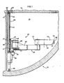
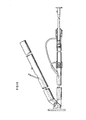
- FIG. 1 depicts a typical recirculating steam generator 10 having a tubesheet 12 and a partition 14 for separating the steam generator head 16 into hotleg and coldleg portions.
- Apparatus embodying the present invention namely a remote manipulator 20, is installed within the head 16 of the recirculating steam generator 10.
- the remote manipulator 20 comprises a mast 22 fastened at one end to the tubesheet 12 by a plurality of anchoring fingers 24 secured within tubes 26, which in turn are fixed in the tubesheet 12.
- the opposite end of the mast 22 includes an adjustable foot 28 which is for securing the bottom of the mast 22 to the bottom of the head 16 and may be pneumatically actuated. Adjustment of the adjustable foot 28 changes the height of the mast 22, permitting its use in steam generators of different dimensions.
- the mast 22 is typically located adjacent and substantially parallel to the partition 14 and substantially along the vertical centre-line of the partition 14 to permit access to the maximum number of tubes by. a tool carrier 30.
- the mast 22 includes a lengthwise screw 32 which carries a movable mounting or trolley plate 34 for providing controlled vertical movement of an articulating arm 36 attached to the mast 22 by a double V-block coupler 38 which, as can better be seen from Figure 12, comprises a male portion 40 attached to the articulating arm 36 and a female portion 42 attached to the mounting plate 34 of the mast 22.
- a male channel trolley 44 attached to the articulating arm 36 mates with a female channel trolley 45, integrally attached to the mast 22, for guiding vertical travel of the articulating arm 36 controlled by rotating the lengthwise screw 32 having the mounting plate 34 attached thereto and controllably driven by a direct current stepper motor 55.
- Six trolley rollers 47 which act like cam followers, and are attached to the movable trolley plate 34, ride in the male channel trolley 44 to provide precise but easy vertical movement.
- the articulating arm 36 comprise an inner or first arm 46 pivotally attached to a trolley mounting plate 48 of the articulating arm 36 and including therein the male portion 40 for attachment to the female portion 42 of the mast 22, and an outer or probe arm 50 pivotally attached to the end of the inner arm 46 remote from the mast 22 and terminating in the tool carrier 30, having a second double V-block coupler 38 and a pneumatic latching pin 43 for attachment of tools.
- Figure 1 shows the articulating arm 36 in a basically extended position, but the two pivoting joints in the arm permit its controlled movement in two dimensions in such a manner that it can locate itself at any position in a plane in a range of 180 degrees of arc by pivoting either or both pivotal joints independently and in either direction.
- Inside an inner junction box 49 is an electrical servo motor 57, having a resolver, for pivoting and controlling the inner arm 46.
- a second servo motor 57 and associated resolver similarly control rotation of the outer arm 50 relative to the inner arm 46.
- the remote manipulator 20 can be used in the bottom half of a recirculating steam generator 10 or in the bottom head of a once through steam generator.
- Certain modifications comprising another embodiment, which will be discussed in detail below, enable the remote manipulator 20 to operate on a 360 degree surface, making it unnecessary to move the remote manipulator 20 in order to reach the tubes that would be in the opposite leg of a recirculating steam generator.
- Yet another modification leads to another embodiment discussed in detail below which permits operation of the basic remote manipulator 20 in the top head of a once through steam generator and also permits operation in a 360 degree plane of rotation.
- an anchor pin 60 having a cable 62 fixedly attached thereto, is fastened inside a previously identified tube in the tubesheet 12 from outside a manway 64.
- the cable 62 extends outside the manway 64 where it is attached to the mast 22 which is hoisted into position by means of a pulley attached to the cable 62.
- Locator pins 66 are aligned with previously identified tubes.
- the appropriate tubes for seating the locator pins 66 are typically marked in advance with a white paint which resists the harsh environment of a steam generator, as is conventional in the industry.
- the adjustable foot 28 of the now vertical downwardly hanging remote manipulator 20 is pneumatically actuated to extend or lengthen, thereby providing a firm base against the bottom of the head 16.
- the mast 22 provides a strong, stiff support for the articulating arm 36, any tools that may be attached thereto and any forces generated during working operations.
- a locator pole 68 ( Figure 3) manually held and manipulated by a man outside the manway 64 may be pushed against the mast 22 to help align the locator pins 66 during installation of the mast 22 in the tubesheet 12, although this is not strictly necessary.
- the locator pole 68 can be detachably connected to the mast 22 to permit multi-directional movement and control of the mast 22 during the seating of the mast locator pins 66.
- the locator pole 68 is not load bearing and its manipulation does not require significant strength; rather, the weight of the mast 22 is borne by the cable 62.
- a pulley cable 70 runs over a pulley attached to the mast 22 and is attached at one end to the mounting block 48 of the articulating arm 36, outside of the manway 64, at a cable fastener 72 near the centre of gravity of the articulating arm 36.
- the pulley cable 70 is introduced into an air motor with winch 59 connected to an articulating arm 36.
- the articulating arm 36 is then hoisted along the pulley cable 70 into position by the air motor with winch 59 and is locked to the mast 22 by the double V-block coupler 38.
- the articulating arm 36 may be guided by the locator pole 68.
- the air motor with winch 59 permits the articulating arm 36 to hoist itself into position and permits the installer to stop the articulating arm 36 at any convenient point along the pulley cable 70 without imposing a load on the installer.
- the outer arm 50 is rotated away from the inner arm 46 to extend the entire articulating arm 36, which is now in the operating position illustrated in Figure 1.
- a tool is attached to the tool carrier 30.
- the tool carrier 30 may be extended to or beyond the edge of the manway 64 to permit ready installation and removal of different tools for performing different tasks. Furthermore, in this position, portions of the articulating arm 36 are accessible for maintenance and repair.
- the remote manipulator 20 is removed from the recirculating steam generator 10 by reversing the installation steps described above.
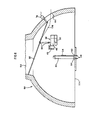
- FIG 4 illustrates another preferred embodiment of the apparatus according to the present invention (the remote manipulator 20) for use in the top or upper head of a once through steam generator 88.
- the remote manipulator 20 in this embodiment comprises a stub-mast 80 fastened to the tubesheet 12 by anchoring fingers 24.
- the top of the stub-mast 80 is not attached to any support, so that, unlike the embodiment described above in connection with the lower head of a steam generator, a base 82 of the remote manipulator 20 provides the entire support for the system.
- the articulating arm 36 is attached to the stub-mast 80 in a fashion similar to that discussed above, although its position is inverted, that is, the outer arm 50 is lower than inner arm 46, the opposite of that relationship in the embodiment discussed above.
- this arrangement permits the tool carrier 30 to be moved closer to the tubesheet 12 since the outer arm 50 can be positioned adjacent to the tubesheet 12 in either embodiment.
- a turntable 84 comprising an integral portion of the stub-mast 80, rests on the base 82 for rotation thereon and the stub-mast 80 is fixedly attached to the turntable 84.
- Rotation of the turntable 84 is controlled pneumatically and the turntable 84 can be locked into any of three positions, namely an initial position wherein the double V-block coupler 38. on the stub-mast 80 faces the manway 64 to permit installation of the articulating arm 36, and two working positions located 90 degrees on either side of the initial position, permitting the remote manipulator 20 to be rotated into either of two working positions 180 degrees of arc apart, permitting the articulating arm 36 to operate with 360 degrees of rotation.
- the tool carrier 30 can thereby reach all tubes within the top head of the once through steam generator, except those tubes located relatively close to the base 82, from one position, and can reach all tubes with one change of position of the remote manipulator 20.
- the tool carrier 30 on the working end of the outer arm 50 can be presented at the manway 64 for changing tools and performing some maintenance on the articulating arm 36.
- an installation support pole 86 used to install the remote manipulator 20, and which may be left in position while the remote manipulator 20 is being used.
- this embodiment can be installed in and removed from the steam generator without having anyone enter the steam generator, although this embodiment is directed only to a remote manipulator for the top head of a once through steam generator.
- the installation support pole 86 is manually inserted into the top head 90 of the once through steam generator 88 by an operator standing outside of the manway 64, who props the remote end of the installation support pole 86 against an inlet neck 94 of the top head 90 and detachably affixes the proximate end of the installation support pole 86 to the inside surface of the top head 90 adjacent the top of the manway 64.
- Previously attached to the installation support pole 86 is a block and tackle 96, suspended from a pulley 98. The lower end of the block and tackle 96 is detachably attached to the top of the stub-mast 80 by a cable hook 81.
- a ratcheting winch 74 By turning a ratcheting winch 74, detachably bolted to the outer flange of the manway 64, an operator outside of the manway 64 actuates a cable 100 causing the block and tackle 96 with the attached stub-mast 80 to travel upwardly along the installation support pole 86.
- a guiding pole 102 may be detachably connected to the sub-mast 80, desirably at a point on or near the base 82, and manipulated by an operator outside the manway 64 to prevent excess swinging of the stub-mast 80 during installation and to help align the anchoring fingers 24 with previously marked tubes. This procedure is not strictly necessary, however, since the stub-mast 80 tends to hang vertically true.
- the stub-mast 80 When the stub-mast 80 has reached the appropriate point near the midpoint of the tubesheet 104 ( Figure 4), it is lowered to the tubesheet 104 by means of the block and tackle 96, remotely operated from outside the manway 64 by a B&T cable 106. Nut runners tighten the anchoring fingers 24 into previously identified tubes as described above. The anchoring pins or fingers 24 are described in more detail below.
- the block and tackle 96 is detached from the top of the stub-mast 80 by a manually operated hooked end cable manipulator 108 ( Figure 9) and returned to its starting position adjacent the manway 64, where the cable hook 81 is attached to the articulating arm 36 at a point near the centre of gravity of the folded articulating arm 36, so as to maintain the articulating arm 36 in a basically horizontal position during installation.
- the articulating arm 36 is moved up the installation support pole 86, just as the stub-mast 80 was.
- the articulating arm 36 when in the appropriate position, is lowered remotely by the block and tackle 96 by the B&T cable 106, whose remote end is outside of the manway 64 and may be positioned with the guiding pole 102 manipulated by an operator outside of the manway 64 during installation.
- an air motor with winch 59 can be employed to remotely lower and position the articulating arm 36, as described above with reference to Figure 3.
- the male portion 40 and female portion 42 of the double V-block coupler 38 are then aligned and mated by simply permitting the articulating arm 36 carrying the male portion 40 to seat in the female portion 42, as described above.
- a pneumatically actuated locking pin is then inserted into aligned openings in the male and female portions of the coupling.
- the block and tackle 96 is then detached from the articulating arm 36 by the hooked end cable manipulator 108 and moved to a position where it will not interfere with the remote manipulator 20.
- the articulating arm 36 is then moved to the manway 64 for attachment of tools to the tool carrier 30.
- the remote manipulator 20 is then ready to perform its computer-controlled conventional locating operations.
- the articulating arm 36 can be moved up and down the stub-mast 80 in the manner described above regarding the preceding embodiment. To remove the remote manipulator 20 from the top head 90, the sequence described above is merely reversed.
- the articulating arm 36 may comprise substantially rectangular tubular members constructed by welding steel plates along their seams.
- the mast 22, stub-mast 80 and articulating arm 36 are constructed primarily of hardened aluminium, which is anodised to resist environmental degradation.
- Other members, fasteners, couplers and the like are desirably made of stainless steel to increase strength and reduce corrosion.
- Pivoting of the joint between the mounting block 48 of the articulating arm 36 and the first or inner arm 46, and between the first arm 46 and the outer or probe arm 50 may be accomplished by conventional direct current electric stepper motors and other types of electric or air motors, such as servo motors, and vertical movement of the articulating arm 36 along the mast 22 or stub-mast 80 may be achieved similarly.
- the installation support pole 86 may be of aluminium, steel, or other suitable material which provides sufficient strength and rigidity.
- Conventional 6 mm (0.25 in) diameter reinforced tubing provides suitable air delivery means for driving the pneumatic actuators that control the remote manipulator 20. Similar tubing is used to control and operate tools that may be attached to the tool carrier 30.
- the articulating arm 36 may be permanently connected to the mast 22, or in the case of a remote manipulator for the upper head of the once through steam generator, the articulating arm 36 may be permanently attached to the stub-mast 80, permitting installation of the entire remote manipulator in a single procedure, such as those discussed above in connection with the mast of a two-piece manipulator.
- Providing a manipulator which can be installed as a single assembly obviously reduces the labour cost and time associated with installation and obviates the necessity for designing a detachable coupling which provides very precise alignment of the articulating arm 36 with the mast 22, or stub-mast 80.
- Such a single assembly is particularly attractive when the remote manipulator will be subjected to light or moderate loads, which naturally reduce the required structural strength and permit substantial reductions in manipulator weight.
- FIG 7 illustrates a locator pin 66 and anchoring finger 24 assembly 120 used to secure the mounting plate of the stub-mast 80 to the tubesheet 12 ( Figure 4).
- the locator pin and anchoring finger assembly 120 has a mounting block 122 for securing two longitudinal members, which may naturally form a portion of a larger mounting plate, such as that which forms the base of the stub-mast 80.
- the locator pin 66 includes a substantially cylindrical body 124 having a reduced diameter fitting end 126 secured in an aperture 128 of the mounting block 122 by press-fitting, welding, or other suitable means.
- a locating end of the locator pin 66 comprises a cone-shaped nose portion 130.
- the anchoring finger 24 includes a mandrel 132 seated in an aperture 134 of the mounting block 122 and having a threaded end 136 which penetrates the mounting block 122 for mating with a nut 138.
- the diameter of the mandrel 132 increases as the shaft goes upwardly.
- the end of the anchoring finger or pin 24 remote from the nut 138 terminates in a cone-shaped nose portion 140. Both nose portions or noses 130, 140 are designed to permit easy penetration of tubes without being precisely aligned with the centre of the tubes and without causing damage to the tubes.
- a sleeve 142 is seated around the tapered body portion of the mandrel 132 above the mounting block 122 and includes a plurality of longitudinal slots 144 in the upper portion of the sleeve 142, providing the sleeve 142 with circumferential flexibility.
- the locator pin 66 is longer than the anchoring finger 24.
- the locator pin 66 may have a diameter somewhat smaller than the inside diameter of the tubes into which it will be inserted.
- the assembly is used for installing the mast 22 into the head of a recirculating steam generator, as illustrated in Figure 2 and described above; and for installing the turntable in the bottom head of a once through steam generator.
- a device similar to that illustrated in Figure 16 is used to align the locator pin 66 with a previously selected tube and to insert and seat the assembly into the tubesheet.
- the locator pin 66 and thereby any apparatus connected to it by the mounting block 122, is positioned so that the small end of the nose portion 130 is within the side wall of the inside of a tube, and the mounting block 122 is then moved upwardly, as illustrated in Figure 7, so that the locator pin 66 is inserted into the appropriate tube until the top surface of the mounting block 122 is adjacent the tube sheet.
- the anchoring finger 24 will naturally also be seated almost entirely within a tube. Tightening the nut 138 draws the mandrel 132 downwardly, causing the circumference of the sleeve 142 to swell thereby pushing the sleeve 142 against the inside side wall of the tube.
- the anchoring finger 24 provides a fastener which acts much like a bolt and nut.
- the metal-to-metal contact permits application of substantial force against the inside of the tube without destruction of soft materials, for example, rubber, which have been used in the past to prevent damage to the tubes.
- the anchoring finger 24 will not damage the tube.
- the anchoring finger 24 includes a shoulder portion 146 extending downwardly beyond the mounting block 122 and having a diameter larger than the diameter of the tube.
- the shoulder portion 146 seats against the tubesheet 104 and the mounting block 122 is spaced away from the tubesheet 104.
- This embodiment of the anchoring finger 24 is used to secure the stub-mast 80 to clear tube plugs or other obstructions protruding from the tubesheet 104. This clearance is not necessary in the case of the locator pin 66 and anchoring finger 24 assembly as used in Figure 7, because the mounting block 122 occupies a much smaller surface area than the base of stub-mast 80.
Landscapes
- Engineering & Computer Science (AREA)
- Mechanical Engineering (AREA)
- Physics & Mathematics (AREA)
- Robotics (AREA)
- High Energy & Nuclear Physics (AREA)
- Thermal Sciences (AREA)
- General Engineering & Computer Science (AREA)
- Manipulator (AREA)
- Monitoring And Testing Of Nuclear Reactors (AREA)
Abstract
Description
- This invention relates to remote manipulators for steam generators.
- In a variety of environments it may be highly desirable to provide a platform or carriage from which various types of work can be conducted remotely. Furthermore, it may be necessary to move the work station relative to the surface or member on which the work is being conducted. Space limitations or biological considerations may make it desirable to control such movement remotely. A prime example of this need is presented by a nuclear steam generator, where it may be necessary to inspect or repair some of the tubes inside the steam generator. Normally, these repairs are only required after the steam generator has been operated, which naturally renders the steam generator radioactive. The level of radioactivity within the steam generator may seriously limit the amount of time a man can spend in the environment. In addition, to work in this environment at all a man must wear bulky and heavy protective gear which severely restricts his mobility, vision and stamina. Therefore, it is desirable and sometimes perhaps necessary to provide remotely operable and controllable means for performing the required work.
- Numerous prior art devices for performing specialised functions, for example directing an eddy current probe through the tubes, have been developed. One such effort is disclosed in US Patent No. US-A-3 913 752, issued to Ward et al on 21 October 1975, which is commonly referred to within the industry as a "finger walker". Such devices are slow, cumbersome, difficult to control and locate precisely and do not retain a firm hold on the tubesheet. Therefore, they are not capable of carrying heavy loads. In addition, such a manipulator is not capable of operating in the top head of a once through steam generator. Furthermore, such devices must be installed and removed by a person who is inside the hazardous steam generator.
- Another such device is disclosed in US Patent No. US-A-4 216 832, issued 12 August 1982 to Galthorne. This device also is capable of operating only in the bottom head of a recirculating steam generator. Furthermore, this device and others of its kind are not capable of remote installation in and removal from a nuclear steam generator. A man must go inside the head of the steam generator to install the device and to remove it.
- Although the time required for installation and removal of the device is less than would be required for a man to enter the steam generator and actually perform the required work, many of the disadvantages of having a man work inside the steam generator still arise because he must be available to install and later remove the device, with the consequent exposure to radiation this entails. Radiation levels inside a nuclear steam generator are two to three times higher than those outside it, even when emissions from the manway (an access port to the steam generator) are included in outside radiation measurement. Thus, a remotely installed and removed apparatus would substantially reduce radiation burn out of jumpers, lowering labour costs and reducing personnel needs.
- One effort to overcome this difficulty is disclosed in general terms in European Patent Application Publication No. EP-A-0 066 791 (Vermaat) published on 15 December 1982. In EP-A-0 066 791, the top of the supporting pole is detachably connected to a mounting rod which extends outside the access port of the steam generator, commonly referred to as a manway, and is held by a man who guides an anchor pin into the tubesheet. The main arm is then guided through the manway on a channel rail and attached to the bottom of the supporting pole. From this position, the main arm is moved up the supporting pole to the work position. In a second embodiment, the apparatus is previously assembled with the main arm being already attached to the supporting pole. In this case, it is not necessary that the main arm be run into the steam generator on the channel rail. Still, however, a man must lift the apparatus to the top of the head of the steam generator, locate the locator tubes and install the anchor pins in the appropriate tubes. The tubes of a nuclear steam generator are typically 15.8 mm (5/8 in) in diameter and are closely packed. It is essential that the anchor pins be located in the correct tubes; otherwise the device will not know where its tool is located. The apparatus weighs in excess of 45kg (1001b) and must be raised approximately 1.5(5ft) by a man who is laterally removed from the apparatus by 0.9 to 1.2m (3 to 4ft). In addition, the man must wear protective clothing to shield him from the radiation emanating from the manway. Thus, installation of this apparatus in either embodiment is a skilled operation requiring great strength combined with considerable dexterity. In addition, the apparatus is capable of operation only in the head of a recirculating steam generator.
- Therefore, a need exists for an apparatus which includes one or more of the following features. It can be remotely installed and removed from a steam generator. It can be operated in a recirculating steam generator, or in the top or bottom head of a recirculating steam generator or a once through steam generator. It is capable of reaching nearly all the tubes of a recirculating steam generator or a once through steam generator from one location. It can reach all tubes of a once through steam generator with one change of position. It is capable of performing a variety of operations with a variety of tools that can be quickly changed while maintaining the ability to locate any individual tube with any individual tool and accordingly is capable of sustaining high loads and forces without substantial deflection.
- Preferred apparatus embodying the invention and described in detail below with reference to the accompanying drawings includes the above-listed features. Various aspects of the apparatus providing various of the features are defined in the appended claims.
- The preferred apparatus described below can be installed and removed from a steam generator without having a man enter the steam generator, that is, remotely. Also, the apparatus is capable of working in either a once through steam generator or a recirculating steam generator. Further, the apparatus can operate in the top head of a once through steam generator. The apparatus is capable also of reaching all tubes in either the top or bottom head of a once through steam generator with one change of position, and capable of reaching the overwhelming majority of tubes without changing position. Yet further, the apparatus is capable of performing a variety of operations with a variety of tools within a steam generator, and will withstand the loads required for virtually any tube work performed in a steam generator while being able to locate itself with sufficient precision to carry out detailed work.
- A brief description of the preferred apparatus follows. Operating from outside a manway, a cable is attached to a designated anchor pin in the tubesheet of a recirculating steam generator, or in the bottom head of a once through steam generator, and a vertical support beam, called a mast, is hoisted into position along the cable. A rod, which is not attached to the mast, may be used to help guide the mast, which is seated in the tubesheet by locator pins. Alternatively, the top of the mast may be equipped with anchoring fingers that expand to provide a firm grip within the appropriate tubes without damaging the tubes. A pneumatically actuated foot is then adjusted downwardly until it firmly grips the floor of the steam generator head, thereby providing a firmly anchored and supported mast.
- The preferred apparatus includes an articulating arm for locating appropriate tubes and positioning tools. The articulating arm is hoisted into position on the mast by means of a cable attached to the mast and may be guided into position with a pole manipulated by a man outside the manway. The articulating arm then locks into position by means of a double V-block coupler or other suitable coupling device, which is reinforced and further locked into coupling position by a pneumatically actuated pin driven into aligned keyways in male and female members of the coupler, or other suitable coupling means. A computer-controlled locating system then orients a tool carrier of the articulating arm within the steam generator and directs movement of the tool carrier to any designated tube for inspection or repair, such as tube cleaning, tube sleeving, eddy current probing, tube welding, tube plugging, tube profilometry measuring or other tasks.
- An embodiment of the preferred apparatus designed to operate in the lower head of a once through steam generator comprises a turntable which is introduced into the steam generator along a cable attached to a locator pin in the same fashion as the mast is installed. The turntable installing apparatus (see Figure 16 of the accompanying drawings), resembling a jack, is likewise installed and is located on the floor of the head of the steam generator. This apparatus lifts the turntable to the tubesheet, where the turntable is anchored into appropriate tubes. In this case the mast is subsequently introduced into the steam generator along a cable attached to the turntable and is then anchored against the turntable. The articulating arm is then installed in the same way it is installed in the recirculating steam generator. The turntable locks into a position in which the double V-block coupler of the mast will face the manway for installation of the articulating arm and tools, and then can be rotated 90 degrees of arc in either direction from the initial position thereby providing two working positions 180 degrees apart, thereby permitting access to the 360 degrees of available tubes in the once through steam generator..
- In another embodiment of the preferred apparatus designed to operate in the top head of a once through steam generator, the apparatus includes a stub-mast affixed to a turntable for introduction into the top head. In this case, an installation support pole carrying a cable leans against the inlet piping in the head of the steam generator and has its opposite end detachably connected to the flange of the manway. The cable is attached to the top of the stub-mast and the stub-mast is hoisted along the installation support pole, from which it hangs attached by a block and tackle. When the appropriate position has been reached, the stub-mast is lowered to the tubesheet by means of the block and tackle and anchoring pins anchor the stub-mast to the tubesheet. The top of the stub-mast is not supported. The articulating arm is introduced into the head of the steam generator by means of a block and tackle attached to the installation support pole. It is hoisted along the installation support pole until it is in position adjacent to the stub-mast and then it is lowered by means of the block and tackle into locking engagement with the stub-mast. The two members are coupled by the double V-block coupler, in the case of the bottom head embodiment. The lower portion of the block and tackle is removed from the articulating arm. The installation apparatus can remain inside the steam generator throughout maintenance work performed by the apparatus, or can be removed, whichever is more convenient.
- In either embodiment, the vertical position of the articulating arm is controlled and the articulating arm moves within a V-shaped channel track, which provides close tolerances and high strength. In the embodiment designed for use in the top head of a once through steam generator, having only bottom support requires a somewhat broader base and stiffer mast.
- In the embodiment for the top of a once through steam generator, the mast is anchored by anchoring fingers which provide a very firm grip on the inner wall of tubes within the steam generator without damaging the tubes. The anchoring fingers comprise a central shaft having a cone-shaped locating nose and a tapered body, the taper providing a smaller diameter near the mounting plate of the mast than near the cone-shaped locating nose, and a threaded end remote from the nose. This central member is encased in an expandable sleeve which illustratively may include a plurality of slots about its circumference to permit easy expansion. After the anchoring fingers have been located in appropriate tubes, a nut runner pulls the threaded central member toward the mast, simultaneously expanding the expandable sleeves to ensure a firm grip on the inside tube wall and pulling the mast toward the tubesheet, thereby securely fastening the mast to the tubesheet.
- Embodiments of the preferred apparatus can present the tool carrier to the manway for quickly changing or adjusting tools without the necessity for entering the steam generator. Tools are attached to the tool carrier of the articulating arm by a double V-block coupler or other suitable fastener.
- All functions are controlled from outside the steam generator. All movement of the articulating arm and tools is controlled by compressed air operating through air motors, air cylinders, and the like, all controlled by a central pneumatic control box or by electrical motors and sensors. To provide operator feedback, a video camera and light are mounted on the apparatus. The computer control which locates the position of the tool carrier is conventional.
- The preferred apparatus is capable of automatic location to within less than 0.25 mm (0.01 in) at a
number 10 side load and can be manually positioned to within less than 0.13 mm (0.005 in). Furthermore, in the bottom head of a steam generator, the apparatus can lift a minimum of 45 kg (100 lb) to the tubesheet and sustain a load of 90 kg (200 lb) applied at the end of the fully extended articulating arm with less than 13 mm (0.5 in) deflection. In addition, the apparatus can operate in an environment of at least 65°C (150°F). The apparatus can position tools weighing more than 45 kg (100 lb) at a speed of 10 rpm with a minimum lateral force of 13.6 kgf (30 Ibf) and can traverse steam generator extremes in a maximum of 30 seconds. The apparatus can be remotely controlled and operated by an operator who is at least 150 m (500 ft) away from the apparatus. - Because the steam generator is radioactive, naturally the apparatus will become radioactive after use. Therefore, particular care was taken during design to ensure that the articulating arm can be disassembled and reassembled simply and readily to permit ease of maintenance. Many maintenance functions, for example, replacement of air motors and locators, can be accomplished in the field in a glove box in half an hour or less.
- The invention is more completely and fully described by the following detailed description, given by way of illustrative and non-limiting example, of preferred apparatus embodying the invention and shown in the accompanying drawings, in which:
- Figure 1 is a plan view of apparatus embodying the present invention installed in a recirculating steam generator which is illustrated in cutaway cross-section;
- Figure 2 shows a mast of the apparatus being installed in a recirculating steam generator;
- Figure 3 illustrates installation of an articulating arm following installation of the mast within a recirculating steam generator;
- Figure 4 illustrates apparatus embodying the present invention completely assembled and installed in the top head of a once through steam generator;
- Figure 5 illustrates installation of a stub-mast by means of an installation support pole and block and tackle in the top head of a once through steam generator;
- Figure 6 illustrates installation of the articulating arm using the same means, with the mast already mounted in the top head of a once through steam generator;
- Figure 7 is a side elevation in partial cross-section of a locator pin and anchoring finger assembly;
- Figure 8 is a side elevation in partial cross-section of an anchoring finger installed in a tube of a steam generator at the tubesheet;
- Figure 9 is a side elevation of a hooked end cable manipulator;
- Figure 10 is a front elevation of the mast for use in the upper head of a once through steam generator;
- Figure 11 is a side elevation of the mast for use in the upper head of a once through steam generator;
- Figure 12 is a front elevation of the mast for use in the lower head of a once through steam generator;
- Figure 13 is a side elevation of the mast for use in the lower head of a once through steam generator;
- Figure 14 is an elevation of the mast for use in the upper head of a once through steam generator, detailing a turntable and base attachment to the tubesheet;
- Figure 15 is a plan view of the turntable and base of Figure 14; and
- Figure 16 is a side elevation in partial cross section of a turntable installation tool for use in the bottom head of a once through steam generator.
- Figure 1 depicts a typical
recirculating steam generator 10 having atubesheet 12 and apartition 14 for separating thesteam generator head 16 into hotleg and coldleg portions. Apparatus embodying the present invention, namely aremote manipulator 20, is installed within thehead 16 of therecirculating steam generator 10. Theremote manipulator 20 comprises amast 22 fastened at one end to thetubesheet 12 by a plurality of anchoringfingers 24 secured withintubes 26, which in turn are fixed in thetubesheet 12. The opposite end of themast 22 includes anadjustable foot 28 which is for securing the bottom of themast 22 to the bottom of thehead 16 and may be pneumatically actuated. Adjustment of theadjustable foot 28 changes the height of themast 22, permitting its use in steam generators of different dimensions. Themast 22 is typically located adjacent and substantially parallel to thepartition 14 and substantially along the vertical centre-line of thepartition 14 to permit access to the maximum number of tubes by. atool carrier 30. Themast 22 includes alengthwise screw 32 which carries a movable mounting ortrolley plate 34 for providing controlled vertical movement of an articulatingarm 36 attached to themast 22 by a double V-block coupler 38 which, as can better be seen from Figure 12, comprises a male portion 40 attached to the articulatingarm 36 and afemale portion 42 attached to the mountingplate 34 of themast 22. As can better be seen from Figure 12, a male channel trolley 44 attached to the articulatingarm 36 mates with afemale channel trolley 45, integrally attached to themast 22, for guiding vertical travel of the articulatingarm 36 controlled by rotating thelengthwise screw 32 having the mountingplate 34 attached thereto and controllably driven by a directcurrent stepper motor 55. Sixtrolley rollers 47, which act like cam followers, and are attached to themovable trolley plate 34, ride in the male channel trolley 44 to provide precise but easy vertical movement. - The articulating
arm 36 comprise an inner orfirst arm 46 pivotally attached to atrolley mounting plate 48 of the articulatingarm 36 and including therein the male portion 40 for attachment to thefemale portion 42 of themast 22, and an outer or probearm 50 pivotally attached to the end of theinner arm 46 remote from themast 22 and terminating in thetool carrier 30, having a second double V-block coupler 38 and apneumatic latching pin 43 for attachment of tools. Figure 1 shows the articulatingarm 36 in a basically extended position, but the two pivoting joints in the arm permit its controlled movement in two dimensions in such a manner that it can locate itself at any position in a plane in a range of 180 degrees of arc by pivoting either or both pivotal joints independently and in either direction. Inside aninner junction box 49 is anelectrical servo motor 57, having a resolver, for pivoting and controlling theinner arm 46. Asecond servo motor 57 and associated resolver similarly control rotation of theouter arm 50 relative to theinner arm 46. - In this basic configuration thereof, the
remote manipulator 20 can be used in the bottom half of arecirculating steam generator 10 or in the bottom head of a once through steam generator. Certain modifications comprising another embodiment, which will be discussed in detail below, enable theremote manipulator 20 to operate on a 360 degree surface, making it unnecessary to move theremote manipulator 20 in order to reach the tubes that would be in the opposite leg of a recirculating steam generator. Yet another modification leads to another embodiment discussed in detail below which permits operation of the basicremote manipulator 20 in the top head of a once through steam generator and also permits operation in a 360 degree plane of rotation. - Referring to Figure 2, an
anchor pin 60, having acable 62 fixedly attached thereto, is fastened inside a previously identified tube in thetubesheet 12 from outside amanway 64. Thecable 62 extends outside themanway 64 where it is attached to themast 22 which is hoisted into position by means of a pulley attached to thecable 62. Locator pins 66 are aligned with previously identified tubes. The appropriate tubes for seating the locator pins 66 are typically marked in advance with a white paint which resists the harsh environment of a steam generator, as is conventional in the industry. Theadjustable foot 28 of the now vertical downwardly hangingremote manipulator 20 is pneumatically actuated to extend or lengthen, thereby providing a firm base against the bottom of thehead 16. Firmly anchored by the compression force at both the top and bottom provided by the extendedadjustable foot 28, themast 22 provides a strong, stiff support for the articulatingarm 36, any tools that may be attached thereto and any forces generated during working operations. A locator pole 68 (Figure 3) manually held and manipulated by a man outside themanway 64 may be pushed against themast 22 to help align the locator pins 66 during installation of themast 22 in thetubesheet 12, although this is not strictly necessary. If desired, thelocator pole 68 can be detachably connected to themast 22 to permit multi-directional movement and control of themast 22 during the seating of the mast locator pins 66. Clearly, however, thelocator pole 68 is not load bearing and its manipulation does not require significant strength; rather, the weight of themast 22 is borne by thecable 62. - Referring to Figure 3, a
pulley cable 70 runs over a pulley attached to themast 22 and is attached at one end to the mountingblock 48 of the articulatingarm 36, outside of themanway 64, at acable fastener 72 near the centre of gravity of the articulatingarm 36. At its other end, thepulley cable 70 is introduced into an air motor withwinch 59 connected to an articulatingarm 36. The articulatingarm 36 is then hoisted along thepulley cable 70 into position by the air motor withwinch 59 and is locked to themast 22 by the double V-block coupler 38. During installation, the articulatingarm 36 may be guided by thelocator pole 68. The air motor withwinch 59 permits the articulatingarm 36 to hoist itself into position and permits the installer to stop the articulatingarm 36 at any convenient point along thepulley cable 70 without imposing a load on the installer. - Following the operation described with reference to Figures 2 and 3, the
outer arm 50 is rotated away from theinner arm 46 to extend the entire articulatingarm 36, which is now in the operating position illustrated in Figure 1. Before operations can be commenced, a tool is attached to thetool carrier 30. By articulating the two joints of the articulatingarm 36, and adjusting the height of the articulatingarm 36, thetool carrier 30 may be extended to or beyond the edge of themanway 64 to permit ready installation and removal of different tools for performing different tasks. Furthermore, in this position, portions of the articulatingarm 36 are accessible for maintenance and repair. - The
remote manipulator 20 is removed from therecirculating steam generator 10 by reversing the installation steps described above. - Figure 4 illustrates another preferred embodiment of the apparatus according to the present invention (the remote manipulator 20) for use in the top or upper head of a once through
steam generator 88. Theremote manipulator 20 in this embodiment comprises a stub-mast 80 fastened to thetubesheet 12 by anchoringfingers 24. The top of the stub-mast 80 is not attached to any support, so that, unlike the embodiment described above in connection with the lower head of a steam generator, abase 82 of theremote manipulator 20 provides the entire support for the system. The articulatingarm 36 is attached to the stub-mast 80 in a fashion similar to that discussed above, although its position is inverted, that is, theouter arm 50 is lower thaninner arm 46, the opposite of that relationship in the embodiment discussed above. Naturally, this arrangement permits thetool carrier 30 to be moved closer to thetubesheet 12 since theouter arm 50 can be positioned adjacent to thetubesheet 12 in either embodiment. - A
turntable 84, comprising an integral portion of the stub-mast 80, rests on thebase 82 for rotation thereon and the stub-mast 80 is fixedly attached to theturntable 84. Rotation of theturntable 84 is controlled pneumatically and theturntable 84 can be locked into any of three positions, namely an initial position wherein the double V-block coupler 38. on the stub-mast 80 faces themanway 64 to permit installation of the articulatingarm 36, and two working positions located 90 degrees on either side of the initial position, permitting theremote manipulator 20 to be rotated into either of two working positions 180 degrees of arc apart, permitting the articulatingarm 36 to operate with 360 degrees of rotation. Thetool carrier 30 can thereby reach all tubes within the top head of the once through steam generator, except those tubes located relatively close to thebase 82, from one position, and can reach all tubes with one change of position of theremote manipulator 20. In this embodiment also, thetool carrier 30 on the working end of theouter arm 50 can be presented at themanway 64 for changing tools and performing some maintenance on the articulatingarm 36. Also illustrated in Figure 4 is aninstallation support pole 86, used to install theremote manipulator 20, and which may be left in position while theremote manipulator 20 is being used. Like the embodiment described above, this embodiment can be installed in and removed from the steam generator without having anyone enter the steam generator, although this embodiment is directed only to a remote manipulator for the top head of a once through steam generator. - Referring to Figure 5, which shows installation of the stub-
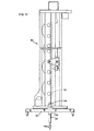
mast 80, theinstallation support pole 86 is manually inserted into thetop head 90 of the once throughsteam generator 88 by an operator standing outside of themanway 64, who props the remote end of theinstallation support pole 86 against aninlet neck 94 of thetop head 90 and detachably affixes the proximate end of theinstallation support pole 86 to the inside surface of thetop head 90 adjacent the top of themanway 64. Previously attached to theinstallation support pole 86 is a block and tackle 96, suspended from apulley 98. The lower end of the block and tackle 96 is detachably attached to the top of the stub-mast 80 by a cable hook 81. By turning a ratchetingwinch 74, detachably bolted to the outer flange of themanway 64, an operator outside of themanway 64 actuates acable 100 causing the block and tackle 96 with the attached stub-mast 80 to travel upwardly along theinstallation support pole 86. If desired, aguiding pole 102 may be detachably connected to the sub-mast 80, desirably at a point on or near thebase 82, and manipulated by an operator outside themanway 64 to prevent excess swinging of the stub-mast 80 during installation and to help align the anchoringfingers 24 with previously marked tubes. This procedure is not strictly necessary, however, since the stub-mast 80 tends to hang vertically true. When the stub-mast 80 has reached the appropriate point near the midpoint of the tubesheet 104 (Figure 4), it is lowered to thetubesheet 104 by means of the block and tackle 96, remotely operated from outside themanway 64 by aB&T cable 106. Nut runners tighten the anchoringfingers 24 into previously identified tubes as described above. The anchoring pins orfingers 24 are described in more detail below. - Referring to Figure 6, which shows installation of the articulating
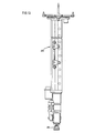
arm 36, the block and tackle 96 is detached from the top of the stub-mast 80 by a manually operated hooked end cable manipulator 108 (Figure 9) and returned to its starting position adjacent themanway 64, where the cable hook 81 is attached to the articulatingarm 36 at a point near the centre of gravity of the folded articulatingarm 36, so as to maintain the articulatingarm 36 in a basically horizontal position during installation. Using the block and tackle 96 andpulley 98, the articulatingarm 36 is moved up theinstallation support pole 86, just as the stub-mast 80 was. The articulatingarm 36, when in the appropriate position, is lowered remotely by the block and tackle 96 by theB&T cable 106, whose remote end is outside of themanway 64 and may be positioned with theguiding pole 102 manipulated by an operator outside of themanway 64 during installation. Alternatively, an air motor withwinch 59 can be employed to remotely lower and position the articulatingarm 36, as described above with reference to Figure 3. The male portion 40 andfemale portion 42 of the double V-block coupler 38 are then aligned and mated by simply permitting the articulatingarm 36 carrying the male portion 40 to seat in thefemale portion 42, as described above. A pneumatically actuated locking pin is then inserted into aligned openings in the male and female portions of the coupling. The block and tackle 96 is then detached from the articulatingarm 36 by the hookedend cable manipulator 108 and moved to a position where it will not interfere with theremote manipulator 20. The articulatingarm 36 is then moved to themanway 64 for attachment of tools to thetool carrier 30. Theremote manipulator 20 is then ready to perform its computer-controlled conventional locating operations. - The articulating
arm 36 can be moved up and down the stub-mast 80 in the manner described above regarding the preceding embodiment. To remove theremote manipulator 20 from thetop head 90, the sequence described above is merely reversed. - The articulating
arm 36 may comprise substantially rectangular tubular members constructed by welding steel plates along their seams. In a preferred form, however, to reduce weight, themast 22, stub-mast 80 and articulatingarm 36 are constructed primarily of hardened aluminium, which is anodised to resist environmental degradation. Other members, fasteners, couplers and the like are desirably made of stainless steel to increase strength and reduce corrosion. Pivoting of the joint between the mountingblock 48 of the articulatingarm 36 and the first orinner arm 46, and between thefirst arm 46 and the outer or probearm 50, may be accomplished by conventional direct current electric stepper motors and other types of electric or air motors, such as servo motors, and vertical movement of the articulatingarm 36 along themast 22 or stub-mast 80 may be achieved similarly. Theinstallation support pole 86 may be of aluminium, steel, or other suitable material which provides sufficient strength and rigidity. Conventional 6 mm (0.25 in) diameter reinforced tubing provides suitable air delivery means for driving the pneumatic actuators that control theremote manipulator 20. Similar tubing is used to control and operate tools that may be attached to thetool carrier 30. - Naturally, the articulating
arm 36 may be permanently connected to themast 22, or in the case of a remote manipulator for the upper head of the once through steam generator, the articulatingarm 36 may be permanently attached to the stub-mast 80, permitting installation of the entire remote manipulator in a single procedure, such as those discussed above in connection with the mast of a two-piece manipulator. Providing a manipulator which can be installed as a single assembly obviously reduces the labour cost and time associated with installation and obviates the necessity for designing a detachable coupling which provides very precise alignment of the articulatingarm 36 with themast 22, or stub-mast 80. Such a single assembly is particularly attractive when the remote manipulator will be subjected to light or moderate loads, which naturally reduce the required structural strength and permit substantial reductions in manipulator weight. - Figure 7 illustrates a
locator pin 66 and anchoringfinger 24 assembly 120 used to secure the mounting plate of the stub-mast 80 to the tubesheet 12 (Figure 4). The locator pin and anchoring finger assembly 120 has amounting block 122 for securing two longitudinal members, which may naturally form a portion of a larger mounting plate, such as that which forms the base of the stub-mast 80. Thelocator pin 66 includes a substantiallycylindrical body 124 having a reduced diameterfitting end 126 secured in anaperture 128 of the mountingblock 122 by press-fitting, welding, or other suitable means. A locating end of thelocator pin 66 comprises a cone-shapednose portion 130. The anchoringfinger 24 includes amandrel 132 seated in anaperture 134 of the mountingblock 122 and having a threadedend 136 which penetrates the mountingblock 122 for mating with anut 138. As oriented in Figure 7, the diameter of themandrel 132 increases as the shaft goes upwardly. The end of the anchoring finger or pin 24 remote from thenut 138 terminates in a cone-shapednose portion 140. Both nose portions ornoses sleeve 142 is seated around the tapered body portion of themandrel 132 above the mountingblock 122 and includes a plurality oflongitudinal slots 144 in the upper portion of thesleeve 142, providing thesleeve 142 with circumferential flexibility. Thelocator pin 66 is longer than the anchoringfinger 24. Thelocator pin 66 may have a diameter somewhat smaller than the inside diameter of the tubes into which it will be inserted. In the configuration illustrated in Figure 7, the assembly is used for installing themast 22 into the head of a recirculating steam generator, as illustrated in Figure 2 and described above; and for installing the turntable in the bottom head of a once through steam generator. A device similar to that illustrated in Figure 16 is used to align thelocator pin 66 with a previously selected tube and to insert and seat the assembly into the tubesheet. - In operation, the
locator pin 66, and thereby any apparatus connected to it by the mountingblock 122, is positioned so that the small end of thenose portion 130 is within the side wall of the inside of a tube, and the mountingblock 122 is then moved upwardly, as illustrated in Figure 7, so that thelocator pin 66 is inserted into the appropriate tube until the top surface of the mountingblock 122 is adjacent the tube sheet. The anchoringfinger 24 will naturally also be seated almost entirely within a tube. Tightening thenut 138 draws themandrel 132 downwardly, causing the circumference of thesleeve 142 to swell thereby pushing thesleeve 142 against the inside side wall of the tube. The more thenut 138 is tightened, the greater is the force exerted against the side wall of the tube. Simultaneously, the mountingblock 122 is drawn against the tubesheet. Thus, the anchoringfinger 24 provides a fastener which acts much like a bolt and nut. The metal-to-metal contact permits application of substantial force against the inside of the tube without destruction of soft materials, for example, rubber, which have been used in the past to prevent damage to the tubes. In addition, the anchoringfinger 24 will not damage the tube. - In another preferred arrangement illustrated in Figure 8, which shows an anchoring
finger 24 installed in a tube adjacent a tubesheet, the anchoringfinger 24 includes ashoulder portion 146 extending downwardly beyond the mountingblock 122 and having a diameter larger than the diameter of the tube. Theshoulder portion 146 seats against thetubesheet 104 and the mountingblock 122 is spaced away from thetubesheet 104. This embodiment of the anchoringfinger 24 is used to secure the stub-mast 80 to clear tube plugs or other obstructions protruding from thetubesheet 104. This clearance is not necessary in the case of thelocator pin 66 and anchoringfinger 24 assembly as used in Figure 7, because themounting block 122 occupies a much smaller surface area than the base of stub-mast 80.
Claims (10)
Applications Claiming Priority (2)
| Application Number | Priority Date | Filing Date | Title |
|---|---|---|---|
| US54022183A | 1983-10-11 | 1983-10-11 | |
| US540221 | 1983-10-11 |
Publications (3)
| Publication Number | Publication Date |
|---|---|
| EP0138583A2 true EP0138583A2 (en) | 1985-04-24 |
| EP0138583A3 EP0138583A3 (en) | 1985-06-19 |
| EP0138583B1 EP0138583B1 (en) | 1989-12-20 |
Family
ID=24154520
Family Applications (1)
| Application Number | Title | Priority Date | Filing Date |
|---|---|---|---|
| EP84306954A Expired EP0138583B1 (en) | 1983-10-11 | 1984-10-11 | Remote manipulators for steam generators |
Country Status (7)
| Country | Link |
|---|---|
| EP (1) | EP0138583B1 (en) |
| JP (1) | JPS60108604A (en) |
| KR (1) | KR870000801B1 (en) |
| BE (1) | BE900811A (en) |
| CA (1) | CA1256145A (en) |
| DE (1) | DE3480775D1 (en) |
| ES (2) | ES8703321A1 (en) |
Cited By (3)
| Publication number | Priority date | Publication date | Assignee | Title |
|---|---|---|---|---|
| EP0434868A1 (en) * | 1989-12-27 | 1991-07-03 | Vermaat Technics B.V. | Apparatus for inspecting and repairing tubes of a nuclear power plant |
| EP0484173A2 (en) * | 1990-11-01 | 1992-05-06 | Westinghouse Electric Corporation | Robotic arm for maintaining a tool in a desired orientation |
| FR2685240A1 (en) * | 1991-12-19 | 1993-06-25 | Expertises Sa Cie Maritime | Handling device with dismantleable structure installed manually between two walls |
Families Citing this family (1)
| Publication number | Priority date | Publication date | Assignee | Title |
|---|---|---|---|---|
| KR200453164Y1 (en) * | 2009-07-31 | 2011-04-15 | (주)일진에너지 | Translating Device for Cooling Water Tank |
Citations (4)
| Publication number | Priority date | Publication date | Assignee | Title |
|---|---|---|---|---|
| US3913752A (en) * | 1973-08-01 | 1975-10-21 | Combustion Eng | Remotely movable platform |
| FR2394374A2 (en) * | 1977-06-15 | 1979-01-12 | Framatome Sa | DEVICE FOR SELECTIVE POSITIONING OF AN ORGAN ON A TUBULAR PLATE |
| US4302146A (en) * | 1978-08-23 | 1981-11-24 | Westinghouse Electric Corp. | Probe positioner |
| EP0066791A1 (en) * | 1981-06-06 | 1982-12-15 | BROWN BOVERI REAKTOR GmbH | Apparatus for carrying out inspectionwork on a steam generator in a nuclear reactor and a method for insersting this apparatus in the chamber of a steam generator |
Family Cites Families (6)
| Publication number | Priority date | Publication date | Assignee | Title |
|---|---|---|---|---|
| IT1093293B (en) * | 1977-03-08 | 1985-07-19 | Westinghouse Electric Corp | APPARATUS FOR REMOTE REPAIR OF PIPES IN A STEAM GENERATOR |
| JPS5440634A (en) * | 1977-09-05 | 1979-03-30 | Minolta Camera Co Ltd | Reflecting mirror of pentagonal roof type |
| US4172492A (en) * | 1977-10-13 | 1979-10-30 | The Babcock & Wilcox Company | Apparatus for the in situ inspection of tubes while submerged in a liquid |
| US4287655A (en) * | 1979-04-30 | 1981-09-08 | Westinghouse Electric Corp. | End effector position and identification system for steam generator servicing machine |
| JPS5633288A (en) * | 1979-08-25 | 1981-04-03 | Mitsubishi Heavy Ind Ltd | Manipulator for work of heat exchanger |
| FR2503920B1 (en) * | 1981-04-08 | 1987-08-21 | Intercontrole Sa | DEVICE FOR POSITIONING A MEMBER OPPOSING THE PERFORATIONS OF A PLATE |
-
1984
- 1984-10-10 CA CA000465070A patent/CA1256145A/en not_active Expired
- 1984-10-10 ES ES536662A patent/ES8703321A1/en not_active Expired
- 1984-10-11 EP EP84306954A patent/EP0138583B1/en not_active Expired
- 1984-10-11 KR KR1019840006279A patent/KR870000801B1/en not_active IP Right Cessation
- 1984-10-11 JP JP59211577A patent/JPS60108604A/en active Granted
- 1984-10-11 DE DE8484306954T patent/DE3480775D1/en not_active Expired - Fee Related
- 1984-10-11 BE BE213823A patent/BE900811A/en not_active IP Right Cessation
-
1985
- 1985-11-15 ES ES548929A patent/ES8802551A1/en not_active Expired
Patent Citations (4)
| Publication number | Priority date | Publication date | Assignee | Title |
|---|---|---|---|---|
| US3913752A (en) * | 1973-08-01 | 1975-10-21 | Combustion Eng | Remotely movable platform |
| FR2394374A2 (en) * | 1977-06-15 | 1979-01-12 | Framatome Sa | DEVICE FOR SELECTIVE POSITIONING OF AN ORGAN ON A TUBULAR PLATE |
| US4302146A (en) * | 1978-08-23 | 1981-11-24 | Westinghouse Electric Corp. | Probe positioner |
| EP0066791A1 (en) * | 1981-06-06 | 1982-12-15 | BROWN BOVERI REAKTOR GmbH | Apparatus for carrying out inspectionwork on a steam generator in a nuclear reactor and a method for insersting this apparatus in the chamber of a steam generator |
Cited By (5)
| Publication number | Priority date | Publication date | Assignee | Title |
|---|---|---|---|---|
| EP0434868A1 (en) * | 1989-12-27 | 1991-07-03 | Vermaat Technics B.V. | Apparatus for inspecting and repairing tubes of a nuclear power plant |
| EP0484173A2 (en) * | 1990-11-01 | 1992-05-06 | Westinghouse Electric Corporation | Robotic arm for maintaining a tool in a desired orientation |
| EP0484173A3 (en) * | 1990-11-01 | 1992-11-25 | Westinghouse Electric Corporation | Robotic arm for maintaining a tool in a desired orientation |
| US5355063A (en) * | 1990-11-01 | 1994-10-11 | Westinghouse Electric Corp. | Robotic system for servicing the heat exchanger tubes of a nuclear steam generator |
| FR2685240A1 (en) * | 1991-12-19 | 1993-06-25 | Expertises Sa Cie Maritime | Handling device with dismantleable structure installed manually between two walls |
Also Published As
| Publication number | Publication date |
|---|---|
| EP0138583B1 (en) | 1989-12-20 |
| ES548929A0 (en) | 1988-06-16 |
| JPH0418203B2 (en) | 1992-03-27 |
| KR850003700A (en) | 1985-06-26 |
| JPS60108604A (en) | 1985-06-14 |
| BE900811A (en) | 1985-02-01 |
| ES8703321A1 (en) | 1987-02-16 |
| ES536662A0 (en) | 1987-02-16 |
| CA1256145A (en) | 1989-06-20 |
| ES8802551A1 (en) | 1988-06-16 |
| EP0138583A3 (en) | 1985-06-19 |
| DE3480775D1 (en) | 1990-01-25 |
| KR870000801B1 (en) | 1987-04-20 |
Similar Documents
| Publication | Publication Date | Title |
|---|---|---|
| US4804038A (en) | Remotely installed, operated and removed manipulator for steam generator | |
| CN105666478B (en) | Joint Manipulator fast assembling-disassembling system and assembly and disassembly methods under nuclear radiation environment | |
| CN112639346A (en) | Pipeline laying equipment | |
| AU2001250690B2 (en) | A method for connection of underwater pipelines and a tool for such connection | |
| US4878694A (en) | Method and device for the remote positioning of an elbow coupling | |
| US11591863B2 (en) | Multifunction handler for handling drilling elements in a drilling rig, drilling rig and related methods for handling drilling elements | |
| EP0263337B1 (en) | Grinding tool and screw installation plate for use in a fuel assembly repair and reconstitution system | |
| US5681033A (en) | Workpiece pick-up jig and positioning tool | |
| EP0138583B1 (en) | Remote manipulators for steam generators | |
| JP2001296384A (en) | Module type underwater repairing device and method | |
| US5368413A (en) | Relating to handling or laying pipes | |
| US5164151A (en) | Manipulator system for an enclosure with a limited access point | |
| JP2010078433A (en) | Remotely-operated device | |
| US4865513A (en) | Portable manway cover handling apparatus | |
| US4590671A (en) | Tool for removing split pin remnants from a nuclear reactor vessel | |
| JPH09159788A (en) | Device and method for remote controlled work in nuclear reactor | |
| EP0263336B1 (en) | Improved reconstitution and repair system for nuclear fuel rod assemblies | |
| US7921750B2 (en) | Power tong frames | |
| JPH06123794A (en) | Device and method for remote incore work | |
| US5017329A (en) | Apparatus for inspecting and repairing the tubes of a nuclear power plant | |
| JP2011089929A (en) | Apparatus and method for piping work in nuclear reactor | |
| JP2543513B2 (en) | Pipe connection equipment associated with offshore drilling equipment | |
| JP2002153023A (en) | Jig and method for pull out of rotor for lateral shaft rotary machine | |
| JPH0763884A (en) | In-reactor remote work device | |
| JPH05333187A (en) | Remote reactor inspection/repairing device |
Legal Events
| Date | Code | Title | Description |
|---|---|---|---|
| PUAI | Public reference made under article 153(3) epc to a published international application that has entered the european phase |
Free format text: ORIGINAL CODE: 0009012 |
|
| PUAL | Search report despatched |
Free format text: ORIGINAL CODE: 0009013 |
|
| AK | Designated contracting states |
Designated state(s): CH DE FR LI SE |
|
| AK | Designated contracting states |
Designated state(s): CH DE FR LI SE |
|
| RHK1 | Main classification (correction) |
Ipc: B25J 19/00 |
|
| 17P | Request for examination filed |
Effective date: 19851122 |
|
| 17Q | First examination report despatched |
Effective date: 19861010 |
|
| GRAA | (expected) grant |
Free format text: ORIGINAL CODE: 0009210 |
|
| AK | Designated contracting states |
Kind code of ref document: B1 Designated state(s): CH DE FR LI SE |
|
| REF | Corresponds to: |
Ref document number: 3480775 Country of ref document: DE Date of ref document: 19900125 |
|
| ET | Fr: translation filed | ||
| PLBI | Opposition filed |
Free format text: ORIGINAL CODE: 0009260 |
|
| 26 | Opposition filed |
Opponent name: ABB PATENT GMBH Effective date: 19900913 |
|
| PLBI | Opposition filed |
Free format text: ORIGINAL CODE: 0009260 |
|
| 26 | Opposition filed |
Opponent name: VERMAAT PIETER HUIBRECHT Effective date: 19900920 Opponent name: ABB PATENT GMBH Effective date: 19900913 |
|
| PLAB | Opposition data, opponent's data or that of the opponent's representative modified |
Free format text: ORIGINAL CODE: 0009299OPPO |
|
| R26 | Opposition filed (corrected) |
Opponent name: ABB PATENT GMBH * 900920 VERMAAT PIETER HUIBRECHT Effective date: 19900913 |
|
| EAL | Se: european patent in force in sweden |
Ref document number: 84306954.3 |
|
| PLBN | Opposition rejected |
Free format text: ORIGINAL CODE: 0009273 |
|
| STAA | Information on the status of an ep patent application or granted ep patent |
Free format text: STATUS: OPPOSITION REJECTED |
|
| 27O | Opposition rejected |
Effective date: 19961126 |
|
| REG | Reference to a national code |
Ref country code: CH Ref legal event code: PUE Owner name: THE BABCOCK & WILCOX COMPANY TRANSFER- BWX TECHNOL |
|
| PGFP | Annual fee paid to national office [announced via postgrant information from national office to epo] |
Ref country code: FR Payment date: 19990917 Year of fee payment: 16 |
|
| PGFP | Annual fee paid to national office [announced via postgrant information from national office to epo] |
Ref country code: SE Payment date: 19990920 Year of fee payment: 16 Ref country code: DE Payment date: 19990920 Year of fee payment: 16 |
|
| PGFP | Annual fee paid to national office [announced via postgrant information from national office to epo] |
Ref country code: CH Payment date: 19990924 Year of fee payment: 16 |
|
| PG25 | Lapsed in a contracting state [announced via postgrant information from national office to epo] |
Ref country code: SE Free format text: THE PATENT HAS BEEN ANNULLED BY A DECISION OF A NATIONAL AUTHORITY Effective date: 20001030 |
|
| PG25 | Lapsed in a contracting state [announced via postgrant information from national office to epo] |
Ref country code: LI Free format text: LAPSE BECAUSE OF NON-PAYMENT OF DUE FEES Effective date: 20001031 Ref country code: CH Free format text: LAPSE BECAUSE OF NON-PAYMENT OF DUE FEES Effective date: 20001031 |
|
| REG | Reference to a national code |
Ref country code: CH Ref legal event code: PL |
|
| EUG | Se: european patent has lapsed |
Ref document number: 84306954.3 |
|
| PG25 | Lapsed in a contracting state [announced via postgrant information from national office to epo] |
Ref country code: FR Free format text: LAPSE BECAUSE OF NON-PAYMENT OF DUE FEES Effective date: 20010629 |
|
| PG25 | Lapsed in a contracting state [announced via postgrant information from national office to epo] |
Ref country code: DE Free format text: LAPSE BECAUSE OF NON-PAYMENT OF DUE FEES Effective date: 20010703 |
|
| REG | Reference to a national code |
Ref country code: FR Ref legal event code: ST |
|
| APAH | Appeal reference modified |
Free format text: ORIGINAL CODE: EPIDOSCREFNO |