KR860002114B1 - Yarn guide transfer apparatus in knitting machine - Google Patents
Yarn guide transfer apparatus in knitting machine Download PDFInfo
- Publication number
- KR860002114B1 KR860002114B1 KR1019850005488A KR850005488A KR860002114B1 KR 860002114 B1 KR860002114 B1 KR 860002114B1 KR 1019850005488 A KR1019850005488 A KR 1019850005488A KR 850005488 A KR850005488 A KR 850005488A KR 860002114 B1 KR860002114 B1 KR 860002114B1
- Authority
- KR
- South Korea
- Prior art keywords
- thread
- guide
- switching device
- movable
- arm
- Prior art date
Links
Images


Classifications
-
- D—TEXTILES; PAPER
- D04—BRAIDING; LACE-MAKING; KNITTING; TRIMMINGS; NON-WOVEN FABRICS
- D04B—KNITTING
- D04B15/00—Details of, or auxiliary devices incorporated in, weft knitting machines, restricted to machines of this kind
- D04B15/38—Devices for supplying, feeding, or guiding threads to needles
- D04B15/54—Thread guides
- D04B15/58—Thread guides for circular knitting machines; Thread-changing devices
- D04B15/60—Thread guides for circular knitting machines; Thread-changing devices with thread-clamping or -severing devices
Landscapes
- Engineering & Computer Science (AREA)
- Textile Engineering (AREA)
- Knitting Machines (AREA)
Abstract
Description
제1도는 환편기의 부분 사시도.1 is a partial perspective view of a circular knitting machine.
제2도는 동 종단면도.2 is a longitudinal cross-sectional view.
제3도는 제2도의 부분 확대도.3 is a partially enlarged view of FIG.
제4도는 실안내와 링부재를 걸거나 벗기는 것을 설명하기 위한 측면도.Figure 4 is a side view for explaining the hanging or peeling off the thread guide and the ring member.
제5도는 제4도에 있어서의 Ⅴ-Ⅴ선에서 본 평면도.FIG. 5 is a plan view seen from the line VV of FIG. 4; FIG.
제6도는 제4도에 있어서의 Ⅵ-Ⅵ선에서 본 정면도.FIG. 6 is a front view seen from line VI-VI in FIG. 4; FIG.
제7도는 실보유/절단장치의 작동을 설명하기 위한 환편기의 부분 사시도.7 is a partial perspective view of the circular knitting machine for explaining the operation of the thread holding / cutting device.
제8도는 2아암레버의 중심축 부근의 단면도.8 is a cross-sectional view near the central axis of the two arm lever.
제9도 및 제10도는 선정(選定)장치의 선정자의 각각의 지지상태와 제어상태를 설명하는 부분 노치사시도.9 and 10 are partial notched perspective views illustrating respective supporting and control states of the selector of the selecting apparatus.
제11도는 선정장치의 평면도.11 is a plan view of the selection device.
제12도는 제11도에 있어서의 XII-XII선 부분 노치 측면도.FIG. 12 is a side view of the notched XII-XII line in FIG. 11. FIG.
제13도는 제11도에 있어서의 XIII-XIII선 측면도.Fig. 13 is a side view of the XIII-XIII line in Fig.11.
제14도는 제13도에 있어서의 XⅣ-XⅣ선 측면도.Fig. 14 is a side view taken along the line XIV-XIV in Fig.13.
* 도면의 주요부분에 대한 부호의 설명* Explanation of symbols for main parts of the drawings
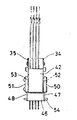
(1) : 실린더 (13), (14), (15), (16) : 링부재(1):
(130), (140), (150), (160) : 가동부재 (132), (142), (152), (162) : 제어스터드(stud)(130), (140), (150), (160): movable members (132), (142), (152), and (162): control studs
(133), (143), (153), (163) : 선정스터드(133), (143), (153), (163): Selection stud
(134), (135), (136) ; (144), (145), (146) ; (154), (155), (156) : 추가스터드134, 135, and 136; 144, 145, 146; (154), (155), (156): additional stud
(137), (147), (157), (167) : 반송(返送)스터드137, 147, 157, and 167: return studs
(19) : 실보유/절단장치(19): thread holding / cutting device
(20) : 가동날(可動刀) (21) : 야안 캐처(Yarn catcher)(20): movable blade (21): Yarn catcher
(22) : 고정날 (26) : 클로오(Claw)(22): Fixed Blade (26): Claw
(28) : 슬라이더 (34), (35) : 측판28:
(47), (48) : 접동부재 (50), (51) : 플레이트47, 48: sliding
(52) : 안내홈 (54), (55) : 핀(52): Guide groove (54), (55): Pin
(56) : 스프링 (61) : 커터캠(Cutter cam)(56): spring 61: cutter cam
(65) : 트래퍼(trapper)부 (66) : 경사부65: trapper portion 66: inclined portion
(67) : 노치부 (68) : 경사포촉부![]()
![]()
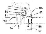
(81) : 2아암래버 (82), (83) : 1아암레버의 아암(81): 2 arm lever (82), (83): 1 arm lever arm
(84) : 홈달린블록 (85) : 플런저(84): Grooved Block (85): Plunger
(90) : 선정장치 (94) : 전자석 블록(90): Selection device (94): Electromagnet block
(97) : U자형상 홈, (100) : 요부(97): U-shaped groove, (100): main part
(101) : 경사부 (102) : 전진캠(101): inclined portion (102): forward cam
(103) : 반송캠 (104) : 경사부103: conveying cam 104: inclined portion
본 발명은 편물기에 있어서의 실공급 전환장치에 관한 것으로 보다 상세히 말하면 출원공고 후에 출 원인에 명의변경된 일본국 소와 52년(1977년) 3월 8일자 출원한 특원소 52-25326호(특개소 52-110964호)의 편물기용 실공급 전환장치의 개량 발명이다.The present invention relates to a thread supply switching device in a knitting machine, and more specifically, to a Japanese country whose name is changed to a cause of release after an application notice, and Japanese Patent Application No. 52-25326 filed on March 8, 1977. 52-110964) is an improved invention of the yarn feed switching device for knitting machines.
상기한바 특원소 52-25326호에 기재된 편물기용 실공급 전환장치는 작용하지 않는 위치와 작용하는 위치와의 사이를 선택적으로 움직이는 여러개의 실안내를 지니고 바늘에 실을 공급할 때에 이 실안내가 프로그램에 따라 제어된 선정장치에 의하여 움직여질 수 잇는 여러개의 편성기구를 지닌 편물기용 실공급전환장치에 있어서,The thread supply switching device for knitting machines described in the above-mentioned special element 52-25326 has a plurality of thread guides which selectively move between the non-acting position and the acting position, and when the thread is supplied to the needle, In the yarn feed switching device for knitting machines having a plurality of knitting mechanisms that can be moved by a selection device controlled accordingly,
(a) 실안내의 일단이 받침점을 피벗한 2아암레버 중의 하나의 아암에 접속되고, 나아가서 이 2 아암레버중의 다른 아암이 가압봉에 접속되어 있는 것.(a) One end of the thread guide is connected to one arm of the two arm levers pivoted, and further the other arm of the two arm levers is connected to the pressure rod.
(b) 전술한 가압봉의 하단부는 U자형상 부재의 안내부내에서 즈름방향 및 수직방향으로 움직일수 있는것(b) the lower end of the pressure bar described above is movable in the slit direction and vertical direction in the guide of the U-shaped member;
(c) 전기한 가압봉의 편물기의 내측으로 면한 부분에는 선정스터드 및 제어스터드가 마련되었으며, 편물기의 외측으로 면한 부분에는 반송스터드가 마련되어 있는 것.(c) Selection studs and control studs are provided on the inner side of the knitting machine of the pressurizing rod, and a conveying stud is provided on the outer side of the knitting machine.
(d)전기한 U자형상 부재에 가압봉의 제어스터드를 밀어올리기 위하여 경사부를 지닌 요부가 마련되었으며 또 가압봉의 반송스터드를 밀어내리기 위해 경사부를 지닌 반송캠이 마련되어 있는 것.(d) The U-shaped member is provided with a recess having an inclined portion for pushing up the control stud of the pressure rod, and a conveying cam with an inclined portion for pushing down the conveying stud of the pressure rod.
(e) 전술한 U자형상 부재에 가압봉을 편물기의 내측에 가입하기 위한 전진캠이 마련되어 있는 것.(e) A forward cam is provided for joining the pressure bar to the inside of the knitting machine in the aforementioned U-shaped member.
(f) 전술한 선정장치가 1개 이상의 선정자를 지니고, 이 선정자가 가압봉의 선정스터드에 선택적으로 작용하는 것,(f) the above-mentioned selection device having at least one selector, which selector acts selectively on the selection stud of the pressure rod,
(g) 전술한 선정자가 전자석에 의하여 선택적으로 "제어"되는 것. 을 특징으로 한다.(g) The selector described above is optionally "controlled" by an electromagnet. It is characterized by.
상술한 종래기술에 있어서는 가동날과 협동 작용하는 고정날에 의하여 절단된 실끝부분은 단일한 실포촉장치에 의하여 여러개의 실끝부분을 간직하고 있기때문에 이종사![]()
![]()
![]()
![]()
또 실포촉장치에는 가동날과 협동 작용하는 고정날에 따라 절단된 실끝부분이 탄력에 의하여 가압 접합 간직되어 있으므로 그 실끝부분이 경우에 따라서는 바늘에 실공급 개시시에는 실이 긴장하여 절단되거나 그렇지 않으면 가동날에 의하여 절단된 잔사(殘![]()
![]()
![]()
![]()
본 발명은 종래기술을 개량하여 보다 성능이 향상한 편물기용 실공급 전환장치를 제공하는 것을 목적으로 한다. 본 발명의 구체적인 목적은 낱낱의 실안내에 실보유/절단 장치를 마련하는 일이다.An object of the present invention is to provide a yarn feeding switching device for a knitting machine, which has been improved in performance by improving the prior art. It is a specific object of the present invention to provide a thread holding / cutting device for each thread guide.
본 발명의 관련하는 목적은 실부스러기가 발생하지 않는 그러한 실끝부분의 보유·절단부를 상술한 보유/절단장체에 마련하는 일이다.A related object of the present invention is to provide a holding / cutting body in the above-described holding / cutting body of such a thread tip in which thread scraping does not occur.
본 발명의 그밖의 관련된 목적은, 절단된 부유사가 편물지에 끌려들어가지 않도록 부유사를 포촉하는 실보유/절단장치에 마련하는 일이다.Another related object of the present invention is to provide a thread holding / cutting device for encouraging the floated yarns so that the cut floats are not attracted to the knitted fabric.
본 발명의 또다른 목적은 실가닥을 어떤 위치에서 다른 위치로 통하는 실안내의 실에 용이하고도 신속하게 실이 동할 수 있는 실안내를 편물기에 마련하는 일이다.It is another object of the present invention to provide a knitting machine in the knitting machine which can move the thread strand easily and quickly to the thread of the thread guide from one position to another position.
상술한 여러가지 목적을 달성하는 본 발명의 편물기용 실공급 전환장치는, 작용하지않는 위치와 작용하는 위치와의 사이를 선택적으로 움직이는 여러개의 실안내를 지니고, 실안내를 프로그램 제어하는 선정장치를 지녔으며, 실안내의 일단이 받침점을 중심으로 고정한 2아암레버 중의 하나의 아암에 접속되고, 나아가서 이 2 아암레버의 다른 아암이 가동부재에 접속되어 있으며, 전술한 가동부재의 하단부는 U자형상홈의 환상 안내부내에서 지름방향 및 수직방향으로 움직일 수 있고, 가동부재의 편물기의 내측에 면한 부분에는 선정스터드가 마련되었으며, 편물기의 외측에 면한 부분에는 반송스터드가 마련되어 있고, U자형상 홈에 가동부재의 제어스터드를 밀어올리기 위하여 경사부를 지닌 오목부가 마련되었으며 또 가동부재의 반송스터드가 밀어내리기 때문에 경사부를 지닌 반송캠이 마련되었고, U자형상 홈에 가동부재를 편물기의 내측에 가압하기 위한 전진캠이 마련되어 있으며, 선정장치가 1개 이상의 선정자를 지니고, 이 선정자가 가동부재의 선정스터드에 선택적으로 작용하여 선정자가 전자석 블록에 의하여 선택적으로 제어되는 편물기용 실공급 전환장치에 있어서 실안내에 대응하여 하나하나에 실을 간직하고 또한 절단하는 실보유/절단장치가 마련되어 있음을 특징으로 한다.The yarn supply switching device for knitting machines of the present invention, which achieves the above-mentioned various objects, has a plurality of thread guides selectively moving between a non-acting position and an acting position, and has a selection device for program control of the thread guidance. One end of the thread guide is connected to one arm of the two arm lever fixed around the support point, and further, the other arm of the two arm lever is connected to the movable member, and the lower end of the movable member described above is a U-shaped groove. It can move in the radial direction and the vertical direction in the annular guide of the member, the selection stud is provided on the part facing the inside of the knitting machine of the movable member, the conveying stud is provided on the part facing the outside of the knitting machine, the U-shaped groove In order to push up the control stud of the movable member, a recess with an inclined portion is provided. Since it is pulled out, a conveying cam with an inclined portion is provided, and a forward cam for pressing the movable member to the inside of the knitting machine is provided in the U-shaped groove, and the selection device has one or more selectors, Thread supply switching device for knitting machines, in which the selector is selectively controlled by an electromagnet block by selectively acting on the selection stud, the thread retaining / cutting device is provided for retaining and cutting the thread one by one in response to the thread guide. It is done.
바람직하기는 실보유/절단장치는 가동날과 야안 캐처와의 사이에 고정날을 병설한 것이며, 이 가동날과 야안캐처를 개구시키기 위한 탄력 지지된 클로오(claw)가 실안내에 마련됨과 동시에 슬라이더를 개재하여 가동날과 야안캐처를 개구시키기 위한 커터캠이 실린더에 마련되어 있다.Preferably, the thread holding / cutting device is provided with a fixed blade between the movable blade and the eye catcher, and at the same time an elastic support claw for opening the movable blade and the eye catcher is provided in the thread guide. A cutter cam for opening the movable blade and the eye catcher via the slider is provided in the cylinder.
더욱 바람직하기는 실안내를 제1작용위치에서 제2작용위치에 움직이는 이동수단이 마련되어 있다. 바람직하기는 실안내를 제1작용위치에서 제2작용위치에 움직이는 이동수단은 2아암레버의 중심축에 마련되어 있는 홈이 달린 블록과, 이 블록 후단부에 작용하도록 마련된 플랜저와 이 플랜저를 상하동시키도록 선정장치에 마련된 플랜저캠으로 되어 있다.More preferably, moving means for moving the thread guide from the first acting position to the second acting position is provided. Preferably, the moving means for moving the thread guide from the first acting position to the second acting position includes a grooved block provided on the central axis of the two arm lever, a flanger provided to act on the rear end of the block, and the flanger up and down. It is a flanger cam provided in the selector.
더욱 좋기로는 실안내가 작용위치에 움직여짐에 따라서 그 실가닥을 안쪽으로 안내하는 경사부와, 이 경사부에 잇따라서 안내된 실가닥을 포촉하는 노치부와, 실안내가 작용하지 않는 위치에 움직여짐에 따라서 절단된 부유사를 포촉하는 경사포 촉부로 이루어진 트래퍼(trapper)부가 실린더에 마련되어 있다.More preferably, the inclined portion for guiding the thread strands inwardly as the thread guide is moved to the acting position, the notch portion for ensuing the guided thread strand following this inclined portion, and the position in which the thread guide does not work. A trapper portion made of a warp cloth tip for enclosing the floated yarn cut as it is moved is provided in the cylinder.
또 바람직하기는 실안내에 실을 끼기위하여 실안내를 안쪽으로 넘어뜨린 전경(前傾)수단이 마련되어 있다.Further, preferably, a foreground means is provided in which the thread guide is turned inward to thread the thread guide.
바람직하기는 실안내를 앞쪽으로 넘어뜨린 전경수단은 양쪽 측판에 마련된 안내홈을 지닌 플레이트와, 이 안내홈에 잇따라서 접동할 수 있는 접동부재와, 각 실안내의 내측단부와 걸거나 벗길 수 있도록 마련된 제1핀 및 접동부재와 양쪽측판에 삽통되어 있는 제2핀과의 사이에 마련된 스프링으로 되어 있다.Preferably, the foreground means for which the thread guide is moved forward is provided with a plate having guide grooves provided on both side plates, a sliding member that can be sequentially connected to the guide groove, and the inner end of each thread guide so as to be able to hang or peel off. A spring provided between the provided first pin and the sliding member and the second pin inserted into both side plates.
다음에 첨부한 도면에 따라 본 발명의 한 실시예를 설명한다.Next, an embodiment of the present invention will be described with reference to the accompanying drawings.
제1도는 환편기의 주요부분 사시도이며, 제2도 및 제3도는 그 종단면도 이다. 이것들의 도면에서 부호(1)는 회전실린더를 나타낸다. 실린더(1)의 외주에는 축선방향으로 뻗는 침흠안을 접동이 자유로운 실린더 침(2)이 수용되어 있다.1 is a perspective view of a main portion of a circular knitting machine, and FIGS. 2 and 3 are longitudinal cross-sectional views thereof. In these drawings, reference numeral 1 denotes a rotation cylinder. At the outer circumference of the cylinder 1, a cylinder needle 2 freely sliding in the needle thread extending in the axial direction is accommodated.
편성시에 실린더침(2)과 협동작용하는 다이얼침(3)은 수평방향으로 배설되어 다이얼(4)에서 반경방향으로 접동이 자유롭다.The dial needle 3 which cooperates with the cylinder needle 2 at the time of knitting is arrange | positioned in the horizontal direction, and is free to slide in the radial direction in the dial 4.
상술한 회전실린더(1)는 베드(bed)(도해없음) 내에 회전할 수 있도록 수용되어 있는 구동기어에 고정되어 있으며 또 다이얼(4)은 니이들 다이얼허브(5)에 연결되어 있다. 이것들 실린더(1) 및 다이얼(4)은 통상기계에 배설되어 있는 구동원으로 부터 구동될대 같은 속도적으로 회전한다.The above-described rotary cylinder 1 is fixed to a drive gear accommodated to rotate in a bed (not illustrated), and the dial 4 is connected to the
상기한 실린더침(2)은 실린더캠호울더(6)에 고정되어 있는 캠(도해없음)에 의하여, 또 다이얼침(3)은 다이얼캡허브(7)의 외측에 마련된 다이얼캠호울더(8)에 고정되어 있는 캠(도해없음)에 의하여 각기 통상의 방법으로 제어된다.The cylinder needle (2) is by means of a cam (not illustrated) fixed to the cylinder cam holder (6), and the dial needle (3) is connected to the dial cam holder (8) provided on the outside of the dial cap hub (7). Each is controlled by a conventional method by means of fixed cams (not illustrated).
제1도에는 2개의 실전환장치(12), (12A)를 나타내고 있으며 각각의 실전환장치에 있어서 야안캐리어(9)가 다이얼 캠호울더(8)에 장치되어 있다. 제7도에서 보여주고 있는바와 같이 이 야안캐리어(9)에는 실전환장치의 상이한 위치에 있는 4개의 실가닥을 안내하는 실안내부(10)와, 안내된 실가닥을 바늘에 실을 공급하는 슬릿(11)이 형성되어 있다.In FIG. 1, two
제1도에서 명백한 바와 같이 실전환장치(12), (12A)에는 각기 4개의 각각의 실가닥을 안내하는 4개의 실안내 (13), (14), (15), (16)가 마련되어 있다. 또 각 실안내의 대략 중앙부에는 안족으로 뻗어있는 핑거(17), (17a, 17b, 17c, 17d)가 있으며, 그 핑거(17)의 유단(遊端)에는 실안내용의 실구멍(18)(18a, 18b, 18c, 18d)이 마련되어 있다. 이것들 실안내(13), (14), (15), (16)는 하부위치 즉, 작용하지않는 위치와, 상부위치 즉, 작용하는 위치와의 사이를 선택적으로 움직이고, 실가닥은 실안내의 실구멍(18)에서 야안캐리어(9)를 거쳐 바늘에 실을 공급한다.As is apparent from FIG. 1, the
제1도에서는 실전환장치(12)의 실안내(16)와 실전환장치(12A)의 실안내(13)만이 작용하는 위치에 있으며, 그것들의 실구멍(18)은 다이얼침(3)의 수준보다도 높은 곳에 있다. 그밖의 실안내는 작용하지않는 위치에 있으며 실구멍(18)은 다이얼침(3)의 수준 보다도 낮은 곳에 있다.In FIG. 1, only the
실가닥을 보유 및 절단하는 것은 실안(13), (14), (15), (16)에 마련된 실보유/절단장치(19)로서 이것이 본발명의 일대 특징을 이루고 있다. 이 실보유/절단장치(19)는 제6도에서 보는바와 같이 가동날(20)과 야안캐처(21)와의 사이에 고정날(22)이 병설된 구조이다. 가동날(20)과 야안캐처(21)는 제3도 및 제7도에서 보는 바와 같이 핀(23)을 중심축으로 회동할 수 있으며, 고정날(22)은 핀(24)과 공통핀(23)의 2개소에서 고정되어 있다. 나중에 설명하는 기구에 따라 야안캐처(21)가 폐구할때 야안캐처(21)와 고정날(22)과의 사이에서 실가닥은 보유된다. 그런 다음 야안캐처(21) 보다 폭의 좁은 가동날(20)이 약간 늦어져서 폐구하여 가동날(20)과 고정날(22)과의 협동 작용에 따라 실가닥은 절단된다.Holding and cutting the thread strands is the thread holding /
가동날(20)과 야안캐처(21)에는 각기 2개의 아암(25a), (25b), (27a), (27b)이 형성되어 있으며, 측심핀(23)과 함게 벨크랭크를 구성하고 있다. 하나의 아암(25a), (25b)은 실안내(13), (14), (15), (16)에 설치되어 있는 클로오(26)와 맞닿을 수 있으며, 또다른 하나의 아암(27a), (27b)은 가동날(20), 야안캐처(21) 및 고정날(22)의 바로 밑에 배설되어 있는 슬라이더(28)의 수직단부와 핀(29)과의 사이에서 움직일 수 있다. 슬라이더(28)는 슬라이더가이드(32)의 홈(33)안을 접동할 수 있는 것으로 그 접동범위는 핀(31)과 이 핀에 걸어맞추고 있는 슬라이더의 긴구멍(30)에 의하여 결정된다.Two arms 25a, 25b, 27a, and 27b are formed on the
가동날(20), 야안캐처(21), 고정날(22), 및 슬라이더(28)는 제3도에서 보는바와 같이 슬라이더가이드(32)에 형성되어 있는 동일 흠(33) 내에 수용되어 있다. 또 핀(23)은 가동날(20), 야안캐처(21), 고정날(22), 슬라이더가이드(32) 및 측판(34), (35)(제5도 참조)의 모두에 삽통되어 있으며, 핀(29), (31)은 측판(34), (35) 및 슬라이더가이드(32)에 삽통되어 있으며, 핀(24)은 고정날(22) 및 측판(34), (35)에 삽통되어 있다. 이것들의 핀(23), (24), (29), (31)의 측방향의 움직임은 스냅팅으로 저지되어 있다. 더우기 측판(34), (35)은 제4도에서 보는바와 같이 2개의 보울트(36)에 의하여 슬라이더가이드(32)에 장치되어 있다. 슬라이더가이드(32)는 제1도에서 보는바와 같이 스트라이퍼링(striper ring)(37)에 장치되어 있으며, 이 스트라이퍼링(37)은 다이얼캡허브(7)에서 연장되어 있는 4 내지 6개의 링호울더(38)에 장치되어 있다.The
다시금 제7도를 참조하면, 각 실안내에는 클로오(26)가 회동할 수 있도록 핀(39)에 지지되어 있으며 또한 스프링(40)에 의하여 실안내(13), (14), (15), (16)의 돌출부(41)에 가압 접합되어 있다. 실안내가 작용하지 않는 위치에서 작용하는 위치에 움직여짐에 수반하여, 이것들 클로오(26)는 가동날(20)의 아암(25a) 및 야안캐처(21)의 아암(25b)에 맞닿는다. 이때 클로오(26)는 스프링(40)에 저항하여 회전하므로 가동날(20)과 야안캐처(21)를 개구시키지 않는다.Referring again to FIG. 7, the thread guides are supported by
이와 반대로 실안내가 작용하는 위치에서 작용하지 않는 위치에 움직여질때에도 클로오(26)는 가동날(20)의 아암(25a) 및 야안캐처(21)의 아암(25b)에 맞닿는다. 그러나 이때에는 클로오(26)의 회동은 실안내의 돌출부(41)에 의하여 저지되므로 클로오는 아암(25a) 및 (25b)를 밀어내리고 가동날(20)과 야안캐처(21)를 개구시킨다. 실안내 (13), (14), (15), (16)는 슬라이더가이드(32)의 바깥쪽에 마련된 홈이 달린 판대기(42)를 길이방향으로 접동할 수 있다. 또 실안내의 상단부에는 링부재(13a), (14a), (15a), (16a)의 일단과 걸거나 벗길 수 있도록 단부를 지닌 핀(43)이 고착되어 있다.On the contrary, the
실가닥을 어떤 위치에서 다른 위치에 통하는 실구멍(18)을 지닌 실안내(13), (14), (15), (16)의 움직임은 핀(45) 및 이 핀(45)에 걸어맞추고 있는 실안내의 긴구멍(44)에 의하여 결정된다. 이 핀(45)은 제5도에서와 같이 측판(34), (35)과 홉이 달린 판대기(42)에 삽통되어 있으며 또한 측방향의 움직임은 스냅링 등으로 저지되어 있다.The movement of the thread guides 13, 14, 15, and 16 with threaded
제4도를 참조하면 흠이 달린 판대기(42)의 아래쪽에는 채널형 부재(46)가 마련되었고, 그 부재(46)의 양쪽에는 접동부재(47), (48)가 나사(49)에 의하여 장치되어 있다. 접동부재(47), (48)는 플레이트(50), (51)의 내면에 형성된 안내홈(52), (53)을 상하방향으로 접동할 수 있다. 이 접동부재(47), (48)의 하단부에 있어서, 채널형부재(46)와 접동부재(47), (48)에 핀(54)이 삽통되어 있다. 이 핀(54)과, 측판(34), (35)에 삽통되어 있는 핀(55)과의 사이에는 스프링(56)이 마련되어 있다. 접동부재(47), (48)의 상단부에는 핀(57)이 고착되어 있으며, 이 핀(57)은 실안내의 내측단부와 접하여 실안내의 가이드를 겸하고 있다. 플레이트(50), (51), 측판(34), (35) 및 홉이 달린 판대기(42)에는 제6도에서 보는바와 같이 2개의 보올트(58)가 삽통되었으며, 그 보울트 단부는 나사(59)에 의하여 고정되어 있다.Referring to FIG. 4, a
채널형 부재(46)의 움직임은 제3도에서 보는바와 같이 상기한 핀(57)과 이 핀(57)에 걸어맞추는 측판(34), (35)의 긴구멍(60)에 의하여 규제된다.The movement of the
실가닥을 어떤 실안내 예컨데(13)에 통하려 할때는 실안내를 작동하는 위치로 하고나서 제4도에 나타낸바와 같이 실안내(13)와 그 링크부재(13a)와의 연결을 끌르고 그런 다음 채널형 부재(46)를 아래쪽으로 끌어내려서 각 실안내의 내측단부와 접촉하고 있는 핀(57)으로 부터 실안내의 하단부를 떼고, 그리고 2점쇄선과 같이 실안내(13)를 앞쪽으로 넘어뜨린다.When attempting to pass the thread strand through some thread guide, for example, 13, pull the connection between the
앞쪽으로 넘어뜨러진 실안내(13)의 실구멍(18a)에는 하등의 장해도 없게 되므로 실가닥을 극히 용이하게 통할 수 있다. 실온 통하고 난 실안내(13)는 위에서 설명한 것과 반대의 조작을 함에 따라 간단히 원래의 위치로 되돌아가게 할 수 있다.Since the
이제 제7도를 참조하여 보면 실린더(1)에는 슬라이더(28)에 대응하는 커터캠(61)이 마련되어 있다. 이 커터캠(61)에는 슬라이더(28)가 2점쇄선과 같이 안쪽으로 밀려나왔을 경우에 실린더(1)의 회전에 수반하여 슬라이더(28)를 바깥쪽으로 밀어주는 경사부(62)가 형성되어 있다.Referring now to FIG. 7, the cylinder 1 is provided with a
이 커터캠(61)은 블록(63) 위에 장치되었는데, 이 블록(63)은 호울더(64)를 개재하여 실린더(1)에 장치되어 있다.This
실안내가 작용하는 위치에서 작용하지 않는 위치에 움직여질 때 실안내(16)의 실구멍(18)에 통하여져 있는 실가닥이 하강함에 따라서 클로오(26)가 가동날(20)의 아암(25a) 및 야안캐처(21)의 아암(25b)에 맞닿아서 이것들을 밀어내리고, 가동날(20) 및 야안캐처(21)를 개구시킨다. 그렇게 되면 실가닥은 개구된 가동날(20)과 야안캐처(21)에 안내된다. 이어서 실린더(1)의 회전에 따라서 커터캠(61)이 슬라이더(28)를 바깥쪽으로 밀어주면 슬라이더(28)의 수직단부가 야안캐처(21)의 아암(27b)을 바깥쪽으로 밀어 준다. 야안캐처(21)는 측심핀(23)을 중심으로 하여 회동하므로 실가닥을 붙잡은 그대로 폐구한다. 이 상태에서는 실가닥은 야안캐처(21)와 고정날(22)과의 사이에서 가압 접합되어 있다. 이어서 야안캐처(21)보다 폭이 좁은 가동날(20)이 조금 늦게 폐구하고 고정날(22)과의 협동작용에 따라 실가닥은 절단된다.When the thread guide is moved from the position at which the thread guide is not acted to the
커터캠(61)의 상방에는 트래퍼부(65)가 실린더(1)에 마련되어 있다. 이 트래퍼부(65)에는 경사부(66)와 노치부(67)가 형성되어 있다. 경사부(66)는 실안내(13)가 작용하지 않는 위치에서 작용하는 위치에 움직여질때에 실안내의 상승에 따라서 그 실구멍(18)으로 통하여져 있는 실가닥이 야안캐처와 고정날에 의하여 유지되어 있는 실가닥의 실끝부분과의 사이에 거의 직립상태로 되므로, 이 직립한 실가닥을 끌어가서 걸기 위한 것이다. 노치부(67)는 경사부(66)에 잇따라서 안쪽으로 안내되는 실가닥이 다른 장소에 이동하지 않도록 함과 동시에 그 실끝부분이 부유하지 않도록 포촉하기 위한 것이다. 이 노치부(67)에 포촉된 실가닥은 실린더(1)의 회전에 수반하여 야안캐리어(9)의 실안내부(10)의 전면을 거쳐 슬릿(11)에 안내되어 바늘에 확실하게 실이 공급된다.The
제7도에서와 같이 실안내(16)가 작용하는 위치에서 작용하지 않는 위치로 움직여질때 다른 작용하지 않는 위치에 있는 실안내(13), (14), (15)의 어느 한개의 실안내가 작용하는 위치에 움직여진다. 제7도에는 실안내(13)가 움직여진 상태를 볼 수 있다. 그 작용하지 않는 위치의 실안내(16)의 실구멍(18d)에 통하여져 있는 실가닥은 전술한 바와 같이 보유/절단장치(19)에 의하여 보유 또는 절단된다. 이때 절단된 실끝부분이 4내지 6cm의 길이로 편물지에 남는다. 이 실끝부분은 연속적인 코오스편성 중에 편물지에 끌려들어가기 쉽다. 이것을 방지하기 위하여 실끝부분을 포촉하는 경사포촉부(68)가 트래퍼부(65)의 후부에 형성되어 있다.As shown in FIG. 7, the thread guides of any of the thread guides 13, 14, and 15 in the other non-acting position when moved from the position where the
각 실안내(13), (14), (15), (16)와 연결되어 있는 링크부재(13a), (14a), (15a), (16a)는 제2도에서와 같이 상술한 다이얼캠호울더(8)의 상방에 마련된 하우징(69)의 홈이 달린 판대기(70), (71)내를 길이 방향으로 접동할 수 있다.The
링크부재(13a), (14a), (15a), (16a)와 실안내의 핀(43)이 걸거나 벗길 수 잇다는 것은 전술하였으나, 그렇게 하기위하여 링크부재의 단부는 원형의 일부가 잘린 반원상부(72)로 되어 있다. 각 하우징(69)은 다이얼캡허브(7)에 고정된 유지구(73)에 담지되었고 도한 측(74)에 피벗되어 있으므로(제8도 참조) 이 측(69)을 중심으로 하여 하우징(73)을 유지구(73)의 상방에서 상하동시킬 수 있다. 이 유지구(73)에는 니이들다이엄허브(5) 내에 관통한 원주체(75)가 아래쪽으로 늘어나와서 설치되어 있다. 다이얼캠호울더(8)의 바깥쪽에는 야안캐리어(9)를 장치하고 있는 호울더(76)상에 스프링플테이트(77)가 설치되었으며, 이 스프링플레이트(77)에 의하여 하우징(69)에 삽통된 핀(78)이 정지되어 하우징(69)의 하단부가 지지되어 있다.It has been mentioned above that the
실안내를 어떤 위치에서 다른 위치에 움직이는 링크부재(13a), (14a), (15a), (16a)의 움직임은 핀(80)과 이핀에 걸어맞추고 있는 링크부재의 긴구멍(79)에 의하여 결정된다. 이 핀(80)은 하우징(69)에 삽통되어 있다. 링크부재(13a), (14a), (15a), (16a)의 다른쪽 끝은 축(74)에 의하여 회전이 자유롭도록 지지된 2아암레버(81)의 한쪽 아암(82)에 장치되어 있으며, 다른 쪽 아암(83)은 가동부재(160)의 상단부용의 기대로 되어 있다.The movement of the
또 제8도에서 보는바와 같이 축(74)에는 홉이 달린 블록(84)이 마련되어 있다.이 흠이 달린 블록(84)은 2아암레버(81)의 일부분을 수용함과 동시에 플런저(85)에 맞닿고 있다. 플런저(85)가 밀어올려지면 홈이 달린 볼록(84)은 축(74)을 중심으로 회동하고 블록(84)에 형성된 경사부(86)에 의하여 2아암레버(81)를 작동시킨다. 이 2아암레버(81)가 움직여짐으로서 작동하지 않는 위치에서 제1작동위치에 움직여진 후에 실안내가 약간 아래쪽의 제2위치에 움직여진다. 이에 따라서 실안내에 마련된 클로오(26)가 가동날의 아암(25a) 및 야안캐처의 아암(25b)에 맞닿아서 가동날(20)과 야안캐처(21)를 조금 개구시킨다. 그렇게 하면 야안캐처(21)와 고정날(22)과의 사이에 지지된 실끝부분이 느슨하여지고 실공급 직후에 있어서의 바늘이 끌려들어감으로서 발생하는 실의 긴장이 느슨하여지게 된다. 이 결과, 실은 실을 공급한 직후에 있어서의 바늘이 끌려들어감으로써 조각조각 찢겨진다거나 하는 일이 없어지고 실부스러기의 발생을 피할 수 있다.As shown in FIG. 8, the
전술한 안쪽으로 밀려나온 슬라이더(28)는 실린더(1)의 회전에 따라 커터캠(61)에 의하여 바깥쪽으로 밀려나오게 되고 이에 따라서 가동날(20)과 야안캐처(21)를 개구시킴과 동시에 제2작용위치에 있었던 실안내가 다시금 제1위치에 복귀하게 된다.The
더우기 상술한 플런저(85)를 밀어올리는 플랜저캠(87)은 제12도에서 보는바와 같이 선정장치의 상부에 일체가 되게 장치되어 있으며, 이 플런저캠(87)에는 상향식 경사부(88)가 형성되어 있다.Furthermore, the
가동부재는 제2도에서 부호(160)로 대표토록 하였으나 4개의 실안내(13), (14), (15), (16)에 대응하여 4개의 가동부재(130), (140), (150), (160)가 마련되어 있다(제9도 및 제10도 참조). 이것들의 가동부재는 다이얼캡허브(7)에 수직으로 배설되어 있으며 유지구(73)의 원통체(89) 내에 드리워져 있다. 이것을 가동부재의 하단은 실안내의 위치에 영향을 주지않고 지름방향으로 요동할 수 있도록 되어 있음과 동시에 실안내가 어떤 위치에서 다른 위치에 움직일 때에는 수직방향으로 접동할 수 있도록 되어 있다.Although the movable member is represented by
제9도 및 제10도는 가동부재(130), (140), (150), (160)하단부의 장치상태를 나타낸 것이다. 가동부재의 편물기의 안쪽으로 면한 부분에는 안내스터드(131), (141), (151), (161) 및 제어스터드(132), (142), (152), (162)가 마련됨과 함게 선정스터드(133), (143), (153), (163)가 장치되어 있으며, 다시 3개씩 추가스터드(134), (135), (136) ; (144), (145), (146) ; (154), (155), (156) ; (164), (165), (166)가 마련되어 있다. 또 편물기의 바깥쪽으로 대면한 부분에는 단일한 반송스터드(137), (147), (157), (167)가 마련되어 있다. 이것들 여러가지 스터드의 특정한 배치 및 작용에 대하여는 선정장치에 관련시켜서 다음에 상세히 설명한다.9 and 10 show the state of the lower end of the
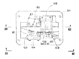
선정장치(90)는 제2도에서 보는바와 같이 니이들다이얼허브(5)의 기저부와 연결하고 있는 플레이트(91)상의 단면 L자형 부재(92) 위에 놓아져 있다. 제14도에 상세히 나타내어 있는바와 같이 단면이 L자형 부재(92)의 개방 대면에는 바깥쪽 림(93)이 마련되어 있다. 단면 L자형 부재(92) 및 바깥쪽 림(93)의 사이에서 형성되는 공간에 전자석 블록(94)이 고정되어 있다. 전자석 볼록(94)은 제13도에서 보는바와 같이 계단상의 홈으로 분할된 2개의 부분(94a), (94b)으로 되어 있다. 아랫부분(94b)에는 코어(95)(95a, 95b, 95c, 95d)가 설정됨과 동시에 제14도에서 보는바와 같이 그 하부에 내측림(96)이 고착되어 있다. 내측림(96)과 외측림(93) 및 단면이 L자형 부재(92)의 저면으로 환상의 U자 형상 홈(97)을 형성한다.The
실안내에 장치된 가동부재(130), (140), (150), (160)의 하단부는 이 U자형상 홈(97)안을 지름방향 및 수직 방향으로 움직일 수 있다. 또 전자석 블톡의 위부분(94a)에는 단면![]()
![]()
![]()
![]()
제9도 및 제10도에 나타내고 있는 바와 같이, U자형상 홈(97)을 구성하는 외측림(98) 정상부는 가동부재의 반송스터드(137), (147), (157), (167)의 하단부와 접촉하도록 형성되어 있으며, 가동부재가 하부위치에 있을 경우 및 가동부재의 하단부가 편물기의 바깥쪽 가까이에 배치되어 있을 경우에는 각각의 실안내가 작용하지 않는 위치가 되도록 한다. 다른 한편, 가동부재가 높은 위치를 잡고, 그 하단부가 편물기의 중심부 가까이에 배치되었을 경우에는 환상홈(97)을 구성하는 내측팀(96) 정상부는 이 시점에서 제어스터드(132), (142), (152), (162)의 하부와 접촉하여 각각의 실안내가 작용하는 위치가 되도록 한다.As shown in Figs. 9 and 10, the top portion of the
U자형상 홈을 구성하는 내측림(6)에는 선저형(船底形)의 요부(100)가 마련되어 있다. 이 요부(100)는 제어스터드(132), (142), (152), (162)의 하단부가 완전히 맞닿도록 깊게 천설되어 있다. 선저형의 상향식 경사부(101)는 가동부재(130), (140), (150), (160)를 높은 위치에 올리는 제어캠으로 되어 있다. 나아가서 선저형의 경사개시부분에 대면하여 외측림(98)에는 전진캠(102)이 고정되어 있으며, 가동부재의 하단부에 작용하여 이 하단부를 편물기의 중심으로 향하여 지름방향으로 가압하며, 그에 따라 각각의 하부 제어스터드를 요부(100)에 배치시키도록하고 있다. 또 U자형상 홈(97)의 외측림(93)의 상단부에는 반송캠(103)이 고정되어 있다. 이 반송캠(103)에는 경사부(104)가 형성되었는데 이 경사부(104)와 요부(100)의 경사부(101)와 이루는 각도는 약 90°이다. 이 경사부(104)는 높은 위치 즉 작용하는 위치의 가동부재의 반송스터드(137), (147), (157), (167)에 작용하여 가동부재를 낮은 위치에 복귀한다.The inner rim 6 constituting the U-shaped groove is provided with a bottom portion recessed
가동부재(130), (140), (150), (160)의 선정, 따라서 가동부재가 장치되어 있는 실안내의 선정은 4개의 선정자(105)(105a, 105b, 105c, 105d)에 의하여 이루어진다. 이들 선정자(105)는 제14도에서와 같이 후단부가 단면 L자형상 부재(92) 위의 기대(106)에 걸리고 전단부가 유단으로 되어 있으나 각 선정자는 스프링플레이트로서 대략 평행하게 지지되어 있다. 각 선정자(105)의 전단에는 제11도에서 보는바와 같이 경사부(107)를 지닌 제어돌출부(108)가 마련되어 있으며, 다음에 기재하는 바와 같이 가동부재의 선정스터드에 작용하도록 되어 있다. 선정자가 걸려있는 경우에 제어돌출부(108)가 수직한 방향으로 변위할 수 있는 크기는 전자석블록(94)의 위부분(94a)과 코어(95) 선단과의 사이에 형성된 계단상의 홈, 즉 공간의 크기에 따라 결정된다. 각 선정자(105)의 중앙부는 제11도에서 보는 바와 같이 크게 오려내어져 있으며, 이 오려낸 부분(109)을 전자석 블록(94)의 계단상 정상부가 관통하고 있다.Selection of the
선정자(105)를 선정하여 제어하는 것은 전자석 블록이다. 이 전자석블록(94)의 코어(95)는 여자되었을 때 대응하는 선정자를 가깝게 끌어당길 수 있다. 전자석을 선택적으로 여자하려면 즉, 선정자를 가깝게 하여 걸리면 고정 프로그램장치에 담지된 정보 프로그램을 전선(도해없음)을 개재하여 정보를 얻을 필요가 있다. 고정 프로그램 장치로서는 예를 들면 광학필름, 천공테이프, 매트릭스, 그밖의 널리 알려진 정보 담지체가 사용된다.Selecting and controlling the selector 105 is an electromagnet block. The core 95 of the
제어스터드(132), (142), (152), (162)의 모두는 동일 수준으로 위치시킬 수 있으나 선정스터드(133), (143), (153), (163)은 어떤 가동부재와 다른 가동부재와는 서로 다른 수준으로 배설되어 있다. 그리고 실안내작용하지 않는 위치에 있을 경우에 이것들 스터드가 4개의 선정자(105)(105a, 105b, 105c, 105d)의 제어돌출부(198)(108a, 108b, 108c, 108d)의 각각의 수준에 대응하도록 되어 있으며 통상은 상방에 가압되어 있다. 또한 이것들 4개의 스터드 사이에는 충분한 수직공간이 마련되어 있으며, 이것들 스터드가 대응하는 전자석코어의 작용하에 하방에서 움직일때에 선정자의 제어돌출부와 접촉하지 않도록 되어 있다.The
다음에 제9도 및 제10도에 따라서 실전환장치의 작용을 설명한다. 니이들다이얼 허브(5)에 의하여 담지 되어 있는 선정장치(90)는 화살표의 방향으로 움직인다. 가령 4개의 실안내의 모두가 작용하지 않는 위치에있을때에 는 각 가동부재의 하단부는 환상의 U자형상 홈(97)에 걸어맞춘다. 전진캠(102)이 4개의 가동부재의 하단부에 연속적으로 작용하여 4개의 가동부재를 편물기의 중심으로 향하여 가압하면 각각의 제어스터드(132), (142), (152), (162)는 내측림(96)의 요부(100)의 수평부분에 걸어맞추도록 된다.Next, the operation of the actual switching device will be described with reference to FIGS. 9 and 10. The
정보프로그램에 따라 선택적으로 여자된 전자석 블록(94)의 코어(95c)의 작용에 따라 특성한 선정자(105c)가 아래쪽에 위치를 정하게 된다. 니이들다이얼허브(5)의 회전시에 선정자(105c)의 제어돌출부(108c)는 대응하는 선정스터드(153)의 밑을 지나고 가동부재(150)는 동일한 위치에 남는다. 이어서 제어스터드(152)는 경사부(101)와 걸어맞추어 환상의 U자형상 홈(97)을 구성하는 내측림(96) 위를 접동한다. 가동부재(150)가 위쪽으로 움직이면이 가동부재에 연결되어 있는 실안내(15)도 움직이며, 실안 내는 작용하는 위치에 놓여지고 실은 편물기의 바늘에 실을 공급하도록 된다. 다른 한편으로 다른 3개의 선정스터드 (133), (143), (153), (163)은 선정자(105a), (105b), (105d) 각각의 제어돌출부(108a), (108b), (108d)에 의하여 되돌려지고 가동부재(130), (140), (160)는 최초의 위치에 되돌아오기 때문에 실안내(13), (14), (16)는 작용하지 않는 위치에 남는다.The
가동부재(130), (140), (150), (160)에 각기 마련된 4개의 다른 추가스터드(134), (135), (136) ; (144), (145), (146) ; (154), (155), (156) ; (164), (165), (166)의 사용법 및 배치에 대하여 설명한다. 각 가동부재와 3개의 추가스터드는 하부 제어스터드와 선정스터드와의 사이에 배설되어 있으며, 가동부재가 상향식 경사부(101)에 의하여 보다 높은 위치에 움직였을 경우에 각 스터드가 3개의 선정자의 제어돌출부(108)의 하나와 동일 수준이 되도록 되어 있다. 선정자가 하방으로 움직일 경우, 즉 각각의 전자석에 의하여 선정될 경우에는 각 스터드는 이들 선정자와 동일 수준으로 되지 않는다.Four other
제10도는 새로운 선정을 하였을 경우에 이루어지는 것을 설명한 것이다. 이 경우에는 선정자(105d)는 코어(95d)의 여자에 따라 하방으로 움직여진다. 이전의 조작으로 선정되어 있는 가동부재(150)는 니이들다이얼허브(5)의 회전중 높은 위치에서 유지되지만 다른 3개의 가동부재(130), (140), (160)는 전진캠(102)의 작용하에 편물기의 중심방향으로 향하게 하여 재차 가압된다. 선정자의 통과시에 가동부재(130), (140)의 선정스터드(133), (143)만이 선장자(105a), (105b)의 제어돌출부(108a), (108b)에 의하여 되돌려지지만 가동부재(160)는 선정자(105d)에 따라서는 작용을 받지않으며 상향식 경사부(101)와 걸어맞추도록 되어 있고 대응하는 실안내(16)가 작용하는 위치에 놓여지고 새로운 실시바늘에 공급이 되도록 된다. 다른 한편 선정자(105c)의 제돌출부(108c)는 이전에 상승하였던 가동부재(150)의 추가스터드(156)를 되돌려주고 이 추가스터드(156)는 편물기의 바깥쪽으로 향하여지게 된다. 그때 반송스터드(157)는 반송캠(103)과 걸어맞추고 가동부재(150)는 낮은 위치로 반송되며 실안내(15)는 작용하지 않는 위치에 되돌려진다.10 illustrates what happens when a new selection is made. In this case, the
상술한 바와 같이 3개의 추가스터드를 사용하면 예비기구를 사용하지 않더라도 선정프로그램을 간단히 제어하는 것만으로 실안내를 용이하게 교환할 수 있다.As described above, if three additional studs are used, the actual guide can be easily exchanged simply by controlling the selection program even without using a spare mechanism.
이상으로 본 발명을 상세하게 그 가장 바람직한 실시형태에 대하여 설명하였는 바 상품의 조합과 배열은 특허 청구의 범위에 반하지 않는 한 여러가지로 변경할 수 있다.As mentioned above, the most preferable embodiment of this invention was described in detail, The combination and arrangement of goods can be changed in various ways, as long as it does not contradict a claim.
Claims (8)
Applications Claiming Priority (3)
| Application Number | Priority Date | Filing Date | Title |
|---|---|---|---|
| JP41496 | 1985-03-02 | ||
| JP85-41496 | 1985-03-02 | ||
| JP60041496A JPS61201057A (en) | 1985-03-02 | 1985-03-02 | Supply yarn change-over apparatus for knitting machine |
Publications (2)
| Publication Number | Publication Date |
|---|---|
| KR860007405A KR860007405A (en) | 1986-10-13 |
| KR860002114B1 true KR860002114B1 (en) | 1986-11-26 |
Family
ID=12609960
Family Applications (1)
| Application Number | Title | Priority Date | Filing Date |
|---|---|---|---|
| KR1019850005488A KR860002114B1 (en) | 1985-03-02 | 1985-07-30 | Yarn guide transfer apparatus in knitting machine |
Country Status (6)
| Country | Link |
|---|---|
| US (1) | US4656842A (en) |
| JP (1) | JPS61201057A (en) |
| KR (1) | KR860002114B1 (en) |
| DE (1) | DE3606611C2 (en) |
| GB (1) | GB2171727B (en) |
| IT (1) | IT1190207B (en) |
Families Citing this family (28)
| Publication number | Priority date | Publication date | Assignee | Title |
|---|---|---|---|---|
| GB8607609D0 (en) * | 1986-03-26 | 1986-04-30 | Camber Int Ltd | Circular knitting machines |
| ES2006232A6 (en) * | 1987-12-04 | 1989-04-16 | Jumberca Sa | Striping system for a circular knitting machine. |
| JP2761926B2 (en) * | 1989-07-05 | 1998-06-04 | 株式会社福原精機製作所 | Yarn feed switching device in circular knitting machine |
| FR2698890B3 (en) * | 1992-12-07 | 1994-11-25 | Wang Ping S | Control system for thread guide changing devices for knitting machines. |
| GB2347149B (en) * | 1995-03-31 | 2000-12-13 | Sipra Patent Beteiligung | A circular knitting machine including a yarn changer |
| DE19511949B4 (en) * | 1995-03-31 | 2009-10-15 | Sipra Patententwicklungs- Und Beteiligungsgesellschaft Mbh | Knitting machine and thread changing device |
| SG82541A1 (en) * | 1995-03-31 | 2001-08-21 | Sipra Patent Beteiligung | A knitting machine and a yarn changer |
| JP3667485B2 (en) * | 1997-02-19 | 2005-07-06 | 株式会社福原精機製作所 | Yarn supply switching method in circular knitting machine |
| ES2153261B1 (en) * | 1997-10-07 | 2001-08-16 | Jumberca Sa | CIRCULAR WEAVING MACHINE FOR POINT GENERATIONS. |
| IT1312329B1 (en) | 1999-05-26 | 2002-04-15 | Mecmor Spa | DEVICE FOR SELECTIVE FEEDING OF WIRES IN BINDING MACHINES OR SIMILAR. |
| US6655176B1 (en) * | 2002-06-27 | 2003-12-02 | Pai Lung Machinery Mill Co., Ltd. | Striping apparatus for circular knitting machines |
| SG112845A1 (en) * | 2002-07-04 | 2005-07-28 | Pai Lung Machinery Mill Co Ltd | Discoloration apparatus for circular knitting machines |
| CN100526530C (en) * | 2004-06-23 | 2009-08-12 | 株式会社福原精机制作所 | Yarn feed switching device for circular loom |
| DE102004032270A1 (en) * | 2004-06-30 | 2006-01-19 | Sipra Patententwicklungs- Und Beteiligungsgesellschaft Mbh | Knitting machine with at least one striping apparatus |
| CN1958908B (en) * | 2005-11-01 | 2011-01-26 | 佰龙机械厂股份有限公司 | Color change head of one-sided tubular knitting machine at high speed |
| US7036343B1 (en) * | 2005-11-07 | 2006-05-02 | Pai Lung Machinery Co., Ltd. | Striping apparatus of a circular knitting machine |
| US7055348B1 (en) * | 2005-11-09 | 2006-06-06 | Pai Lung Machinery Mill Co., Ltd. | High speed color altering head for single-face circular knitting machines |
| SG132522A1 (en) * | 2005-11-18 | 2007-06-28 | Pai Lung Machinery Mill Co Ltd | A striping apparatus of a circular knitting machine |
| SG132520A1 (en) * | 2005-11-18 | 2007-06-28 | Pai Lung Machinery Mill Co Ltd | High speed color altering head for single-face circular knitting machines |
| ITMI20061877A1 (en) * | 2006-09-29 | 2008-03-30 | Santoni Spa | FEEDER FOR THREADS FOR KNITTING MACHINES, PARTICULARLY FOR CIRCULAR KNITTING MACHINES |
| TWM361512U (en) * | 2008-12-29 | 2009-07-21 | Zhi-Liang Wei | Thread-changing set for discoloration head |
| CN101922084B (en) * | 2009-06-16 | 2012-01-04 | 洪荣豪 | Yarn carrier of circular knitting machine |
| DE102009040739A1 (en) * | 2009-09-08 | 2011-03-10 | Sipra Patententwicklungs- Und Beteiligungsgesellschaft Mbh | Method and knitting machine for making knitwear with striped patterns |
| US7845196B1 (en) * | 2010-04-07 | 2010-12-07 | Pai Lung Machinery Mill Co., Ltd. | Circular knitting machine having integrated multiple yarn changing apparatus |
| ITBS20130086A1 (en) * | 2013-06-21 | 2014-12-22 | Santoni & C Spa | DEVICE FOR POWERING THE WIRE TO THE NEEDLES OF A TEXTILE MACHINE |
| US9441317B1 (en) * | 2015-06-04 | 2016-09-13 | Pai Lung Machinery Mill Co., Ltd. | Yarn clipping and cutting structure for striping apparatus of circular knitting machine |
| DE102016110981A1 (en) * | 2016-06-15 | 2017-12-21 | Sipra Patententwicklungs- Und Beteiligungsgesellschaft Mbh | Circular knitting machine |
| CN113026170B (en) * | 2021-03-16 | 2022-01-11 | 海宁市恒通经编有限公司 | Yarn guide mechanism for warping machine |
Family Cites Families (14)
| Publication number | Priority date | Publication date | Assignee | Title |
|---|---|---|---|---|
| US3018646A (en) * | 1962-01-30 | Feeding attachments for circular knitting machines | ||
| GB367084A (en) * | ||||
| US1129261A (en) * | 1913-12-13 | 1915-02-23 | Hemphill Mfg Company | Circular-knitting machine. |
| GB512170A (en) * | 1938-04-28 | 1939-08-30 | William Arthur Reader | Improvements in or relating to yarn changing mechanism for knitting machines |
| US2295450A (en) * | 1939-06-23 | 1942-09-08 | Toone Nottingham Ltd B | Knitting machine |
| AT241666B (en) * | 1963-07-02 | 1965-08-10 | Elitex Zavody Textilniho | Device for clamping non-working threads when the thread guides are switched off on a circular knitting machine |
| GB1328757A (en) * | 1971-04-06 | 1973-09-05 | Stibbe Machinery Ltd | Yarn feeding and changing mechanism for circular knitting machines |
| AR205337A1 (en) * | 1972-12-19 | 1976-04-30 | Poudres & Explosifs Ste Nale | INSTALLATION FOR THE CONCENTRATION BY SUPPLY OF HEAT OF A DILUTED SOLUTION OF CORROSIVE PRODUCTS |
| IT1005799B (en) * | 1974-02-28 | 1976-09-30 | Mecmor Spa | YARN FEEDING DEVICE FOR CIRCULAR MACHINES FOR KNITWEAR WITH FIXED CYLINDER AND ROTATING CAM COVERS FOR THE MANUFACTURE OF OPEN FABRIC |
| GB1531472A (en) * | 1975-01-24 | 1978-11-08 | Wildt Mellor Bromley Ltd | Device for trapping fringe yarns in a circular knitting machine |
| FR2343845A1 (en) * | 1976-03-08 | 1977-10-07 | Asa Sa | INSTALLATION FOR CHANGING THE POWER WIRES IN A CIRCULAR KNITTING Loom |
| FR2379632A2 (en) * | 1976-03-08 | 1978-09-01 | Asa Sa | Circular knitter yarn cutter-clamp - including a fixed blade with each yarn change unit and a moving blade acting successively on fixed blades |
| GB2059448B (en) * | 1979-09-28 | 1983-03-23 | Wildt Mellor Bromley Ltd | Yarn feeder and changer unit |
| JPS5747956A (en) * | 1980-09-04 | 1982-03-19 | Fukuhara Seiki Seisakusho | Yarn supply switching apparatus of circular knitting machine |
-
1985
- 1985-03-02 JP JP60041496A patent/JPS61201057A/en active Granted
- 1985-07-30 KR KR1019850005488A patent/KR860002114B1/en not_active IP Right Cessation
-
1986
- 1986-02-21 US US06/831,640 patent/US4656842A/en not_active Expired - Lifetime
- 1986-02-28 GB GB08605056A patent/GB2171727B/en not_active Expired
- 1986-02-28 IT IT47701/86A patent/IT1190207B/en active
- 1986-02-28 DE DE3606611A patent/DE3606611C2/en not_active Expired - Fee Related
Also Published As
| Publication number | Publication date |
|---|---|
| GB2171727B (en) | 1988-10-26 |
| DE3606611A1 (en) | 1986-09-04 |
| US4656842A (en) | 1987-04-14 |
| JPH0372740B2 (en) | 1991-11-19 |
| IT1190207B (en) | 1988-02-16 |
| JPS61201057A (en) | 1986-09-05 |
| GB8605056D0 (en) | 1986-04-09 |
| IT8647701A0 (en) | 1986-02-28 |
| DE3606611C2 (en) | 1994-07-14 |
| KR860007405A (en) | 1986-10-13 |
| GB2171727A (en) | 1986-09-03 |
Similar Documents
| Publication | Publication Date | Title |
|---|---|---|
| KR860002114B1 (en) | Yarn guide transfer apparatus in knitting machine | |
| US4385507A (en) | Yarn feeding and changing apparatus for circular knitting machines | |
| KR0123800B1 (en) | Sinker mechanism for knitting machine | |
| JP2005042260A (en) | Feed yarn changeover apparatus for circular knitting machine and changeover method | |
| EP0407196B1 (en) | Yarn changing apparatus for circular knitting machine | |
| JPS6025535B2 (en) | Yarn feed switching device for knitting machines | |
| US3006173A (en) | Yarn clamping and cutting means and method for knitting machines | |
| JP3667485B2 (en) | Yarn supply switching method in circular knitting machine | |
| US3225571A (en) | Apparatus for yarn severing in circular knitting machines | |
| EP0683257B1 (en) | Circular knitting machine with knitting retention sinkers | |
| GB1583594A (en) | Knitting machines | |
| US2959040A (en) | Circular knitting machines of the superimposed needle cylinder type | |
| US3147604A (en) | Yarn take-up means for knitting machines | |
| US4364246A (en) | Knitting machine | |
| JP2000328403A (en) | Yarn feed shifting apparatus for knitting machine | |
| US3090216A (en) | Method of yarn severing in circular knitting machines | |
| US1827660A (en) | Yarn changing means for circular knitting machines | |
| US2270432A (en) | Yarn binder for knitting machines | |
| US1917763A (en) | Knitting machine | |
| US1086570A (en) | Knitting-machine. | |
| JPH0121988Y2 (en) | ||
| US2122845A (en) | Yarn changer for knitting machines | |
| US2286955A (en) | Elastic yarn feeding means for knitting machines | |
| US3995456A (en) | Device for trapping fringe yarns in a circular knitting machine | |
| US1837470A (en) | Yarn changing mechanism for knitting machines |
Legal Events
| Date | Code | Title | Description |
|---|---|---|---|
| A201 | Request for examination | ||
| G160 | Decision to publish patent application | ||
| E701 | Decision to grant or registration of patent right | ||
| GRNT | Written decision to grant | ||
| FPAY | Annual fee payment |
Payment date: 20001019 Year of fee payment: 15 |
|
| LAPS | Lapse due to unpaid annual fee |