KR860001614B1 - Composite flexible pulp refiner disk and method of making the same - Google Patents
Composite flexible pulp refiner disk and method of making the sameInfo
- Publication number
- KR860001614B1 KR860001614B1 KR1019840005206A KR840005206A KR860001614B1 KR 860001614 B1 KR860001614 B1 KR 860001614B1 KR 1019840005206 A KR1019840005206 A KR 1019840005206A KR 840005206 A KR840005206 A KR 840005206A KR 860001614 B1 KR860001614 B1 KR 860001614B1
- Authority
- KR
- South Korea
- Prior art keywords
- tablet
- disk
- disc
- refined
- adhesive
- Prior art date
Links
Images


Classifications
-
- D—TEXTILES; PAPER
- D21—PAPER-MAKING; PRODUCTION OF CELLULOSE
- D21D—TREATMENT OF THE MATERIALS BEFORE PASSING TO THE PAPER-MAKING MACHINE
- D21D1/00—Methods of beating or refining; Beaters of the Hollander type
- D21D1/20—Methods of refining
- D21D1/30—Disc mills
- D21D1/303—Double disc mills
-
- D—TEXTILES; PAPER
- D21—PAPER-MAKING; PRODUCTION OF CELLULOSE
- D21B—FIBROUS RAW MATERIALS OR THEIR MECHANICAL TREATMENT
- D21B1/00—Fibrous raw materials or their mechanical treatment
- D21B1/04—Fibrous raw materials or their mechanical treatment by dividing raw materials into small particles, e.g. fibres
- D21B1/06—Fibrous raw materials or their mechanical treatment by dividing raw materials into small particles, e.g. fibres by dry methods
- D21B1/08—Fibrous raw materials or their mechanical treatment by dividing raw materials into small particles, e.g. fibres by dry methods the raw material being waste paper; the raw material being rags
- D21B1/10—Fibrous raw materials or their mechanical treatment by dividing raw materials into small particles, e.g. fibres by dry methods the raw material being waste paper; the raw material being rags by cutting actions
-
- D—TEXTILES; PAPER
- D21—PAPER-MAKING; PRODUCTION OF CELLULOSE
- D21D—TREATMENT OF THE MATERIALS BEFORE PASSING TO THE PAPER-MAKING MACHINE
- D21D1/00—Methods of beating or refining; Beaters of the Hollander type
- D21D1/20—Methods of refining
- D21D1/30—Disc mills
- D21D1/306—Discs
Abstract
Description
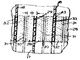
제1도는 본 발명의 특징을 구체화한 유연성 디스크 펄프 정제기의 종단면도.1 is a longitudinal sectional view of a flexible disk pulp purifier incorporating features of the present invention.
제2도는 제1도와 동일한 면에서 취한 정제 디스크 조립체 일부의 부분 확대도.2 is an enlarged partial view of a portion of a tablet disk assembly taken in the same plane as in FIG.
제3도는 본 발명에 따르는 유연성 정제 디스크의 제작순서를 도시한 도식도.3 is a schematic diagram illustrating a manufacturing procedure of the flexible tablet disk according to the present invention.
* 도면의 주요부분에 대한 부호의 설명* Explanation of symbols for main parts of the drawings
28,32,34 : 링 플레이트 29 : 샌드위치 면28, 32, 34: ring plate 29: sandwich side
30,31 : 정제표면 43 : 구조접화제30,31: tablet surface 43: structural bonding agent
44, 47 : 응고영역44, 47: solidification zone
본 발명은 제지용 펄프를 정제하는 정제기에 관한 것으로서 특히 새롭게 개량된 유연성 정제디스크와 그 제조법에 관한 것이다.BACKGROUND OF THE
종래의 제지용 원료 정제법은 원료를 딱딱한 마모면 즉 정제면 사이를 통과시켜 섬유성 재료를 분쇄하여 분리시키며 섬유를 물리적으로 변화시키는 것이다.The conventional papermaking raw material refining method is to pass the raw material between the hard wear surface, that is, the tablet surface, to crush and separate the fibrous material, and to physically change the fibers.
이같은 목적을 위한 정제기에 있어서의 실질적인 개량은 1983년 4월 18일에 출원된 존비. 매츄와 에드워드 씨. 커체너의 특허번호 486,006의 계류중인 출원서에서 밝혀졌으며 본 출원의 양수인에게 양도되었다. 그것에 의하면 회전 디스크 정제기가 필요한 강성률 문제는 해결되며 정제기의 구조와 작업에 있어서의 실질적인 개량은 탄성적으로 유연한 정제표면 지지 디스크를 설치함으로써 얻어지는데 본 디스크는 정제표면의 최적의 작업효과를 달성하기 위해서 이들 정제표면 서로에 대해 회전조절되는 것에 감응하는 작업압력을 지탱한다. 특히 탄성적으로 유연한 정제표면 지지수단은 환형의 정제표면을 구비하며 이것은 디스크 외부 가장자리에 샌드위치 장착되며 한편 본 디스크의 반대편 가장자리는 정제기 장치내에 고정장착된다. 본 정제플레이트는 나사와 리벳같은 기계적 수단에 의해 디스크의 가장자리에 고정되는데 이러한 고정방법은 드릴링, 탭핑 및 패스너와 같은 상당한 기계가공이 필요하게 된다. 이같은 고정방법의 일정한 두께 허용오차 문제는 정제기내의 디스크 조립체의 원하는 허용오차 정확도를 감소시킨다. 제지 펄프정제에 필요한 정제표면의 밀접한 협동관계에 있어서 최적의 효과를 획득하기 위해서는 고도의 정확성이 요구된다. 본 발명이 우선적으로 지향하는 것은 바로 이와같은 난점을 해결하는 것이다.Substantial improvements in refiners for this purpose are described in Johnby, filed April 18, 1983. Machu and Edward. Issued in pending patent application No. 486,006 to Cherchaner and assigned to the assignee of the present application. It solves the problem of stiffness required for rotary disc refiners and substantial improvements in the structure and operation of the refiners are achieved by the installation of elastically flexible tablet surface support discs. These tablet surfaces support the working pressure in response to being rotated relative to each other. In particular, the elastically flexible tablet surface support means has an annular tablet surface, which is sandwich mounted to the disc outer edge while the opposite edge of the disc is fixedly mounted in the refiner device. The tablet plate is secured to the edge of the disc by mechanical means such as screws and rivets, which requires a significant machining such as drilling, tapping and fasteners. The constant thickness tolerance problem of this fixation method reduces the desired tolerance accuracy of the disc assembly in the purifier. A high degree of accuracy is required to achieve optimal effects in close cooperation of the refined surface required for paper pulp refining. The present invention is directed to solving this difficulty.
본 발명의 목적은 특히 제지용 펄프를 정제하는데 사용되는 장치내의 유연한 디스크 구조를 실질적으로 개량하며, 유연한 정제디스크상에 정제링 플래이트를 장착하는 방법을 개량하며, 이같은 유연한 정제디스크를 제작하는 새롭고도 개량된 방법을 제공하는 것이다.It is an object of the present invention, in particular, to substantially improve the flexible disk structure in the apparatus used to purify paper pulp, to improve the method of mounting the tablet ring plate on the flexible tablet disk, and to produce a new and flexible tablet disk. It is to provide an improved method.
본 발명의 원리에 따르면 다수의 반경 방향으로 연장되며 상대적인 회전이 가능하며 축방향으로 대향해 있으며 이것이 상대적인 회전을 하는 동안에 원료가 정제되어 이들 사이에서 유동하게 되는 정제표면 수단 및 이 정제표면 수단 아이를 가로질러서 반경방향으로 원료를 유동시키는 수단에 의해 미립자재료를 분쇄하기 위한 장치내에는, 전기한 정제표면 수단의 일부를 제공하며 이것의 일단을 따라서 장치내에 공정시키는 수단을 구비하는 축방향으로 탄성적으로 유연한 최소한 1개이상의 환형 정제 디스제와, 전기한 디스크보다 폭이 좁으며 디스크의 일단을 샌드위칭하여 정제표면을 제공하는 한쌍의 정제링 플래이트와, 전기한 정제링 플래이트를 전기한 디스크의 가장자리에 고정하기 위해 이들 사이에 구조 접착제막이 제공된다.According to the principles of the present invention, there is provided a tablet surface means and a tablet surface means which extend in a plurality of radial directions and which are capable of relative rotation and are axially opposed and in which the raw material is purified and flows therebetween during the relative rotation. In the apparatus for pulverizing particulate material by means of flowing raw material radially across, an axially elastic means is provided which provides a portion of the above refined surface means and means for processing in the apparatus along one end thereof. At least one annular tablet dispensing agent, a pair of tablet ring plates that are narrower than the disks described above and are sandwiched at one end to provide a tablet surface; Structural adhesive films are provided between them to secure them.
또한 본 발명은 다수의 반경방향으로 연장되며 상대적 회전이 가능하며 축방향으로 대향하고 있어서 이들이 상대적인 회전운동을 하는 동안에 원료가 정제되어 이들 사이에서 원료가 유동하게 되는 정제표면 수단에 의해 미립자 재료를 분쇄하기 위한 장치내에는, 전기한 정제표면 수단의 일부를 제공하며 이것의 일단을 따라 본 정제기 내에 구동연결되는 수단을 구비하는 축방향으로 탄성적으로 구부릴 수 있는 환형 정제 디스크와, 전기한 디스크보다 폭이 좁으며 디스크의 일단을 샌드위칭하여 정제표면을 제공하는 한쌍의 정제링 플래이트와, 전기한 정제링 플래이트를 전기한 디스크의 일단에 고정하기 위해 이들 사이에 구조접착제막을 제공한다.In addition, the present invention is a plurality of radially extending and relatively rotatable and facing in the axial direction so that the raw material is refined during the relative rotational movement to crush the particulate material by means of the purified surface means that the raw material flows between them In the apparatus therefor, an axially elastically bent annular tablet disc having a portion of said tablet surface means and having a drive driven along the end thereof in the present refiner, and wider than said disk A pair of purifying ring plates sandwiching one end of the disk to provide a tablet surface and a structural adhesive film therebetween to secure the aforementioned purifying ring plates to one end of the electric disk are provided.
본 발명은 또한 다수의 반경방향으로 연장되며 상대적인 회전운동이 가능하며 축방향으로 대향하고 있어서 이들이 상대적인 회전운동을 하는 동안에 원료가 정제되는 한편 이들 사이에서 원료가 유동하게 되는 정제표면에 의해 미립자 재료를 분쇄하기 위한 장치에 사용하기 위한 정제디스크 제작법, 즉 축방향으로 탄성적으로 구부릴 수 있는 환형의 정제 디스크의 준비, 전기한 디스크를 이것의 일단을 따라 본 정제기에 구동적으로 고정하기 위한 수단 제공, 전기한 디스크보다 폭이 좁으며 디스크의 가장자리를 샌드위칭하는 한쌍의 정제링 플래이트의 제공, 디스크의 가장자리와 전기한 정제링 플래이트의 샌드위치면에 구조 접착제막을가하기, 전기한 접착제를 경화시켜 전기한 정제링 플래이트를 전기한 디스크의 가장자리에 고정시키기의 순서를 포함하는 정제 디스크 제작법을 제공한다.The present invention also provides a plurality of radially extendable and relatively rotational movements that are axially opposed so that the particulate material is formed by a tablet surface through which the raw material is refined while the raw material flows therebetween during their relative rotational movement. Method of making a tablet disk for use in an apparatus for grinding, ie preparing an annular tablet disk that can be elastically bent in the axial direction, providing a means for driving the fixed disk along the one end thereof to the present tablet, Provide a pair of refining ring plates that are narrower than the discs described above and sandwich the edges of the discs, apply a structural adhesive film to the edges of the discs and the sandwich surface of the refining ring plate, and harden the refining adhesives. The order of fixing the ring plate to the edge of the loaded disk It provides a tablet comprising a disk fabrication method.
여타의 목적 및 본 발명의 유리점은 도면을 참고로 하여 다음의 설명에 의해서 명확해질 것이다.Other objects and advantages of the present invention will become apparent from the following description with reference to the drawings.
본 발명의 유연성 디스크 정제기 조립체(5)는 여러가지 섬유성 재료를 개개의 섬유로 분해하도록 하는 것이며, 특히 목재펄프를 정제하여 제지원료를 제조하는 제지 산업에 적용된다. 여기서는 단일 설비의 정제기 조립체를 예로써 도시했으나 본 발명에 의하면 일련의 정제기 조립체에 의해서 펄프섬유가 점차적으로 분해되는 펄프 정제도 이해할 수 있을 것이다.The flexible disk purifier assembly 5 of the present invention is intended to decompose various fibrous materials into individual fibers, and is particularly applied to the paper industry for refining wood pulp to produce papermaking materials. Although a single plant refiner assembly is shown here by way of example, it will be appreciated that the pulp refinement of the pulp fibers is progressively degraded by a series of refiner assemblies.
채택된 장치에서 전기한 조립체(5)는 고정하우징(7)을 구비하며 여기서 샤프트(8)는 베어링 구조(9)를 구비하는 종래의 베어링 수단상에서 회전되도록 지지되며, 본 샤프트는 모터(도시되지 않음)와 같은 수단을써서 구동된다. 샤프트(8)의 자유단에는 샤프트 스터브(10)가 구동축으로 연장되어 있다. 정제로우러(12)용 허브(11)는 키(13)에 의해 스터브(10)에 연결되어 허브와 스터브가 같이 회전한다. 샤프트(8)가 회전하는 상태에서, 하우징(7)에 의해서 경계가 결정되는 정제실(14)내에서는 로우터(12)가 회전한다. 정제 스테이터(15)는 정제실(14)내에 설치되어서 로우터(12)와 협동한다. 비록 로우터(12)가 내. 외경이 이보다 큰 유연성 정제 디스크(18) 다수와 협동하게 되는 1개의 정제디스크(17)를 구비할지라도 단일개의 로우터 디스크(17)는 스레이터 조립체(15)내의 고정 정제내조와 간단히 협동할 수도 있다. 도시된 예에서는 3개의 로우터 디스크(17)가 2개의 스테이터 디스크(18)와 서로 엇갈린 형태로써 협동되며 또한 고정된 정제 스레이터 구조와 협동한다.The assembly 5 described in the adopted device has a fixed housing 7, where the shaft 8 is supported to rotate on a conventional bearing means having a bearing structure 9, the shaft being a motor (not shown). Drive). At the free end of the shaft 8, the shaft stub 10 extends to the drive shaft. The
바람직한 배열로는 본 로우터 디스크(17)가 허브(11)에 정확하게 종방향으로 이격되어 장착되는 것이다. 볼트(19) 및 볼트를 따라서 디스크의 가장자리에 개재하는 스패이서(17a)는 본 디스크(17)를 허브(11)에 고정시킨다. 축받이 판(20)은 볼트(21)에 의해 스터브(10)의 종단에 고정되며 보호캡(22)은 스터브단에서 조립체에 고정된다. 로레이터 디스크(17)와 동축으로 협동하는 스레이터 디스크(18)용 지지몰이 정제실(14)의 내면을 결정하는 반경방향으로 연장되어 있는 벽(25)에 나사(24)로써 고정된 환형 장착판에 의해 제공된다. 볼트(27)는 스테이터 디스크(18)의 외면을 장착판(23)에 반경방향으로 고정한다.In a preferred arrangement, the
스테이터 디스크 및 로테이터 디스크 사이에 개제하는 면이 정제 플래이트 수단이 되며 이 목적을 위해서 각 로테이터 디스크(17)의 반경 방향의 외면에 로테이터 디스크보다 폭이 좁은 한쌍의 환형 정제링 플래이트가 장착된다. 링 플래이트(28)는 로우터 디스크(17)가 사이에 끼게되는 샌드위치 면(29)이 구비된다. 정제 플래이트(28)상의 서로 대면하는 정제표면(30)은 동일한 직경으로 스테이터 디스크(18)에 의해 운반되는 인접해 있는 정제링 플래이트(32)상의 대면하는 정제표면(31)과 좁은 간격으로써 협동한다. 링 플래이트(28)와 마찬가지로 정제 플래이트(32)는 서로 대면해 있으면서 스테이터 디스크(18)를 사이에 끼는 샌드위치면(33)을 구비하며 링플래이트(32)의 서로 대면하는 정제표면(31)은 링 플래이트(28)의 정제표면(30)이 서로 협동하도록 조정된다.The surface interposed between the stator disk and the rotator disk serves as a tablet plate means, and for this purpose, a pair of annular tablet ring plates narrower than the rotator disk are mounted on the radially outer surface of each
정제 로우터(12)의 서로 반대편단에서 맨끝의 정제 디스크(17)는 맨끝의 정제 플래이트(28)의 정제표면을 구비하며 이 정제링 플래이트(28)는 이와 동심으로 동일한 넓이를 가지는 정제링 플래이트(34)와 협동적인 정제간격 관계를 이루며 정제링 플래이트(34)는 스레이터 조립체의 일부를 포함하며 스레이터 조립체의 일단에서 스레이터 지지물(23)에 의해 지지되며 스레이터 조립체의 반대편에서 장착링(35)에 의해 지지된다. 본 장착링(35)은 폐쇄판(37)에 의해 지탱되며 폐쇄판(37)은 볼트(38)에 의해 하우징(7)에 고정되며 정제실(14)의 반대편벽(25)에 대하는 한 측면을 결정한다.At opposite ends of the tablet rotor 12, the
정제될 펄프 원료는 로우터(12)와 동축으로 정제실(14)로 들어가는 유입구(39)에 의해 정제실(14)에 전달되어 협동하는 로우터 정제디스크와 스레이터 정제 디스크에 의해 제공되는 정제영역에 균일하게 가로지르게 하며 특히 로우터 정제 디스크와 스레이터 정제 디스크의 축방향으로 대면하는 정제 플래이트 표면 사이에서 전 펄프 원료는 유출구(40)를 통하여, 도면에 도시되어 있는 바와같이 유출구(40)는 일반적으로 정제실(14)로부터 반경방향쪽으로 즉 정접방향 쪽으로 연장된다. 균일한 원료의 흐름과 균일한 정제를 촉진하기 위해 본 로우터 디스크(17)에는 개구(41)가 제공되는 것이 바람직하며 이들 개구는 유입구(39)에 가까운 디스크(17)에서부터 정제실(14)의 반대편에 있는 디스크(17)로 갈수록 점차 개구의 크기가 커진다. 펄프 원료가 로우터 정제표면과 스테이터 정제표면에 의해 협동적으로 제공되는 연마정제틈을 통해 반경방향으로 통과한 후 스레이터 디스크 지지물을 통하는 반경 방향의 개구(42)에 의해 제공되는 통로에 의해 정제실의 외부 원주를 향해 지나간 후 유출구(40)를 통해 정제실(14)로부터 나가게 된다. 물론 원한다면 처리될 정제원료 흐름방향을 역으로 할 수도 있는데 이때는 유출구(40)가 유입구가 되고 유입구(39)가 유출구로 된다. 또한 로우터와 스테이터의 순서도 역으로 바꿀 수가 있으며 이때 로우터(12)는 스테이터가 되며 스테이터는 로우터가 된다.The pulp material to be refined is transferred to the refinery chamber 14 by an inlet 39 entering the refinery chamber 14 coaxially with the rotor 12 to a refinery zone provided by the cooperating rotor refiner disc and the shunt refiner disc. The entire pulp stock is passed through the
정제 디스크가 축방향으로 탄성적으로 유연하므로 정제 디스크(17 및 18)는 이들 정제 디스크에 의해 지지되는 정제링 플래이트 사이의 균일한 정제작용을 위하여 효과적으로 중심이 자동적으로 맞추어지는 것이 요망된다. 바꾸어 말하면 이들 정제디스크(17 및 18)는 정제 플래이트를 구비한 정제 디스크가 상대적인 회전을 하는 동안에 정제틈 사이를 가로지르는 원료에 의해 발생되는 동력적인 유체 압력에 감응하게 된다.실제적인 구조에서, 로우터 정제 디스크(17)의 외경은 약 18인치, 스테이터 디스크(18)의 외경은 약 24인치, 링플레이트(28,32,34)의 외경은 약 18인치 내경을 14인치이며 요망되는 디스크(17 및 18) 두께는 약 0.070인치로서 디스크 재료는 섬유 유리이다. 정제링 플래이트(23,32,34)는 두께가 약 0.375인치인 스레인레스스틸로 제작되며 이들의 정제표면에는 높이와 폭이 약 0.062인치이고 이들 사이의 간격이 약 0.187인치인 리브가 있으며 이들 리브는 정제 플래이트의 내단으로부터 외단으로 향하여 원하는 방향으로 경사를 이루고 있다.Since the tablet disk is elastically axially flexible, it is desired that the
정제링 플래이트(28,32)를 정제 디스크(17,18)에 부착함에 있어서 본질적인 개량은 기계적인 수단에 의해 부착하는 것이 아니고 링플래이트를 디스크에 접착시키는 것이다. 이같은 접착은 애폭시(epoxy) 접착제와 같은 구조적 접착제에 의해서 행해지며 이 애폭시 접착제는 각 링플래이트를 지지하는 정제디스크(17,18)의 가장자리와 디스크(17)를 사이에 끼게되는 샌드위치면(33) 사이에 고정 접착막(43)으로써 가해진다. 디스크에 정제플레이트를 이와같이 부착시키는 것은 보다 경제적인 부착방법일 뿐만 아니라 구조 접착제는 표면의 불균일성을 조절하는 역할을 하는 접착선을 제공한다. 즉 이것은 표면의 불균일성을 보정하여 제2도에서 기호 " "로써 나타낸 바와같이 디스크/정제 플레이트 조립체의 임계두께 허용오차를 얻는데 도움이 된다.An essential improvement in attaching the
또한 디스크(17 및 18)의 재료가 접착제와 동일한 방법으로 경화되도록 적용된 곳에서 디스크/정제 플래이트 조합체는 한번의 조작으로 경화되도록 조절될 수도 있다. 예로써 디스크(17 및 18)의 재료가 섬유유리/애폭시이 복합체이고 접착제가 애폭시 접착제인 곳에서 디스크와 접착제의 경화가 동시에 실제적으로 된다. 물론 필요에 따라 본 디스크는 완전히 조립부품으로 조립하여 정제플래이트에 부착할 수도 있다.The disc / tablet plate combination may also be adjusted to cure in one operation where the material of the
제3도의 예에서와 같이 로우터 정제 디스크(17)는 섬유유리 또는 섬유유리/애폭시 판재로부터 스탬핑하거나 또는 이들 재료를 주조하여 제작할 수 있다. 원한다면 경화되지 않은 디스크(17)는 경화영역(44) 내에서 경화될 수도 있으며 또는 도면에서 화살표로 표시한 바와같이 경화영역(44)을 바이패스할 수도 있다. 경화가 되었든 안되었든간에 디스크(17)이 양면에 애폭시와 같은 구조접착제(43)를 경화되지 않은 얇은 막의 상태로 가하여 이곳에 링 플래이트(28)의 샌드위치면(29)이 맞물리게 하거나 또는 정제링 플래이트의 샌드위치면에 접착제막을 가할 수도 있다. 다음에 링플래이트와 디스크(17)는 조립되어지며 조립된 것은 경화영역(47)에 도입되어 여기에서 접착제막이 경화되며 또한 디스크(17)도 동시에 경화된다. 이렇게하여 접착막(43)은 정제링 플래이트를 디스크의 가장자리에 단단하게 고정시키게 된다. 스테이터 디스크(18)와 정제링 플레이트(32) 사이의 접착도 동일한 방법으로 행해진다.As in the example of FIG. 3, the
정제 디스크(17)용 재료를 여기서는 섬유유리나 섬유유리-애폭시 복합물질로 선택했으나 스카치 플라이 보강플래스틱타입 1002 크로스플라이와 같은 고탄성 계수를 구비한 여타의 재료를 사용하거나 혹은 스프링 스텐레스스틸과 같은 적절한 재료를 사용할 수도 있다. 재료의 선택 및 두께의 선선택은 디스크가 축방향으로 탄성적인 굽힘 즉 굽힘성(유연성) 구비하도록 해야 하며 또한 디스크를 가동할 때 발생하는 토크 및 원심려 부하에 효과적으로 저항할 수 있도록 반경방향 및 원둘레방향의 굽힘에 절대적인 저항력을 갖도록 선택해야 한다. 정제플래이트는 경스텐레스스틸, 세라믹과 같은 비교적 경도가 높고 구부러지지 않는 내마모성 재료를 사용해야 한다.The material for the
본 발명의 새로운 개념으로부터 벗어나지 않은 한도내에서는 다양한 변경 및 개조도 가능하다.Various changes and modifications are possible without departing from the novel concept of the invention.
Claims (14)
Applications Claiming Priority (3)
| Application Number | Priority Date | Filing Date | Title |
|---|---|---|---|
| US530,008 | 1983-09-07 | ||
| US530008 | 1983-09-07 | ||
| US06/530,008 US4620675A (en) | 1983-09-07 | 1983-09-07 | Composite flexible pulp refiner disk |
Publications (2)
| Publication Number | Publication Date |
|---|---|
| KR850002514A KR850002514A (en) | 1985-05-13 |
| KR860001614B1 true KR860001614B1 (en) | 1986-10-14 |
Family
ID=24112086
Family Applications (1)
| Application Number | Title | Priority Date | Filing Date |
|---|---|---|---|
| KR1019840005206A KR860001614B1 (en) | 1983-09-07 | 1984-08-27 | Composite flexible pulp refiner disk and method of making the same |
Country Status (10)
| Country | Link |
|---|---|
| US (1) | US4620675A (en) |
| EP (1) | EP0136963A3 (en) |
| JP (1) | JPS6071791A (en) |
| KR (1) | KR860001614B1 (en) |
| BR (1) | BR8404389A (en) |
| CA (1) | CA1240191A (en) |
| DE (1) | DE136963T1 (en) |
| ES (1) | ES8604328A1 (en) |
| FI (1) | FI843220A (en) |
| PH (1) | PH21034A (en) |
Families Citing this family (16)
| Publication number | Priority date | Publication date | Assignee | Title |
|---|---|---|---|---|
| FI80087C (en) * | 1986-05-13 | 1990-04-10 | Yhtyneet Paperitehtaat Oy | MALBLOCK VID EN RAFFINOER. |
| US4966651A (en) * | 1988-01-14 | 1990-10-30 | P.H. Glatfelter Company | Method of paper making using an abrasive refiner for refining bleached thermochemical hardwood pulp |
| JPH086077Y2 (en) * | 1989-09-05 | 1996-02-21 | 相川鉄工株式会社 | Disc refiner for papermaking |
| SE468601B (en) * | 1991-04-12 | 1993-02-15 | Harry Nilsson | FIBER SUSPENSION MALAWARE |
| US5425508A (en) * | 1994-02-17 | 1995-06-20 | Beloit Technologies, Inc. | High flow, low intensity plate for disc refiner |
| US5467931A (en) * | 1994-02-22 | 1995-11-21 | Beloit Technologies, Inc. | Long life refiner disc |
| US5823453A (en) * | 1995-11-14 | 1998-10-20 | J & L Fiber Services, Inc. | Refiner disc with curved refiner bars |
| KR100391974B1 (en) * | 1996-06-14 | 2003-11-28 | 주식회사 코오롱 | Aromatic polyamide pulp, method of manufacturing the same and refiner disk therefor |
| WO1998009018A1 (en) * | 1996-08-26 | 1998-03-05 | Beloit Technologies, Inc. | Refiner having center ring with replaceable vanes |
| US5988538A (en) * | 1998-07-28 | 1999-11-23 | J&L Fiber Services, Inc. | Refiner disc having steam exhaust channel |
| DE19955009C2 (en) * | 1999-11-16 | 2001-10-18 | Voith Paper Patent Gmbh | Process for the production of sets for the mechanical processing of suspended fiber material |
| DE10258324B4 (en) * | 2002-12-13 | 2008-03-27 | Voith Patent Gmbh | Process for the production of sets for the milling of hydrous paper pulp |
| FR2908791B1 (en) * | 2006-11-22 | 2008-12-26 | Acieries De Bonpertuis Soc Par | REFINING ELEMENT FOR FIBERS, IN PARTICULAR PAPERS AND REFINERY USING SUCH A MEMBER |
| US9040712B2 (en) | 2013-01-23 | 2015-05-26 | Novartis Ag | Thiadiazole analogs thereof and methods for treating SMN-deficiency-related-conditions |
| US10166546B2 (en) * | 2013-05-15 | 2019-01-01 | Andritz Inc. | Reduced mass plates for refiners and dispersers |
| US11707742B2 (en) * | 2020-11-24 | 2023-07-25 | Valmet Technologies Oy | Refiner disc and hub assembly |
Family Cites Families (7)
| Publication number | Priority date | Publication date | Assignee | Title |
|---|---|---|---|---|
| US2567448A (en) * | 1951-09-11 | Flexible rotor | ||
| US360670A (en) * | 1887-04-05 | Grain-scourer | ||
| US2991020A (en) * | 1960-04-29 | 1961-07-04 | Ed Jones Corp | Double-disk refiner |
| US3117603A (en) * | 1961-08-25 | 1964-01-14 | Norton Co | Abrasive sectors and mounting apparatus |
| US3326480A (en) * | 1965-01-21 | 1967-06-20 | Jones Division Beloit Corp | Disk refiner |
| US4102505A (en) * | 1976-12-08 | 1978-07-25 | Inox Industria E. Comercio De Aco S/A | Pulp refining disk |
| US4531681A (en) * | 1983-04-18 | 1985-07-30 | Beloit Corporation | Flexible disk refiner and method |
-
1983
- 1983-09-07 US US06/530,008 patent/US4620675A/en not_active Expired - Fee Related
-
1984
- 1984-08-15 FI FI843220A patent/FI843220A/en not_active Application Discontinuation
- 1984-08-17 CA CA000461290A patent/CA1240191A/en not_active Expired
- 1984-08-27 KR KR1019840005206A patent/KR860001614B1/en active IP Right Grant
- 1984-08-30 JP JP59179467A patent/JPS6071791A/en active Granted
- 1984-09-03 BR BR8404389A patent/BR8404389A/en unknown
- 1984-09-04 PH PH31180A patent/PH21034A/en unknown
- 1984-09-04 EP EP84630129A patent/EP0136963A3/en not_active Withdrawn
- 1984-09-04 DE DE198484630129T patent/DE136963T1/en active Pending
- 1984-09-06 ES ES535705A patent/ES8604328A1/en not_active Expired
Also Published As
| Publication number | Publication date |
|---|---|
| PH21034A (en) | 1987-06-30 |
| BR8404389A (en) | 1985-07-30 |
| ES535705A0 (en) | 1986-01-16 |
| CA1240191A (en) | 1988-08-09 |
| ES8604328A1 (en) | 1986-01-16 |
| FI843220A (en) | 1985-03-08 |
| FI843220A0 (en) | 1984-08-15 |
| US4620675A (en) | 1986-11-04 |
| DE136963T1 (en) | 1986-05-22 |
| JPH0220758B2 (en) | 1990-05-10 |
| EP0136963A2 (en) | 1985-04-10 |
| EP0136963A3 (en) | 1987-01-14 |
| KR850002514A (en) | 1985-05-13 |
| JPS6071791A (en) | 1985-04-23 |
Similar Documents
| Publication | Publication Date | Title |
|---|---|---|
| KR860001614B1 (en) | Composite flexible pulp refiner disk and method of making the same | |
| US3473637A (en) | Metal supported carbon friction disc | |
| PL160962B1 (en) | Saw blade | |
| US2580781A (en) | Flexible drive coupling | |
| US4531681A (en) | Flexible disk refiner and method | |
| US4619414A (en) | Multi-disk refiner | |
| KR890000817B1 (en) | Flexible spoke rotor for multiple disk refiner | |
| CA1250479A (en) | Rigid link multiple disk refiner | |
| US3746266A (en) | Waste disintegrator rotor and ring assembly | |
| US4625926A (en) | Multiple disk refiner with elastomeric mounting | |
| US3289954A (en) | Disk refiner | |
| FI84189C (en) | Refiner for processing of fiber material | |
| US20020166912A1 (en) | Fitting carrier and its use | |
| JPS6071792A (en) | Disc refiner | |
| EP1582762B1 (en) | Brake disc | |
| SU1730228A1 (en) | Saw drum for processing fibrous materials | |
| JPS61146895A (en) | Papermaking multi-plate type refiner | |
| JPS6319635B2 (en) | ||
| JPS61215790A (en) | Refiner disc assembly | |
| SU1242343A1 (en) | Grinding wheel | |
| SU889405A1 (en) | Device for fixing abrasive wheel | |
| CN85103088A (en) | Composite flexible pulp refiner disk and method for making thereof | |
| JPS63229181A (en) | Air flow type sorter | |
| RU94024631A (en) | Fittings of disk mill |
Legal Events
| Date | Code | Title | Description |
|---|---|---|---|
| E701 | Decision to grant or registration of patent right |