KR860001325B1 - Signal interference protection circuit for am stereo receiver - Google Patents
Signal interference protection circuit for am stereo receiver Download PDFInfo
- Publication number
- KR860001325B1 KR860001325B1 KR1019830002528A KR830002528A KR860001325B1 KR 860001325 B1 KR860001325 B1 KR 860001325B1 KR 1019830002528 A KR1019830002528 A KR 1019830002528A KR 830002528 A KR830002528 A KR 830002528A KR 860001325 B1 KR860001325 B1 KR 860001325B1
- Authority
- KR
- South Korea
- Prior art keywords
- signal
- stereo
- output
- receiver
- detector
- Prior art date
Links
- 230000004044 response Effects 0.000 claims abstract description 4
- 230000002452 interceptive effect Effects 0.000 abstract 2
- 238000001514 detection method Methods 0.000 description 19
- 238000010586 diagram Methods 0.000 description 12
- 230000005540 biological transmission Effects 0.000 description 4
- 230000000694 effects Effects 0.000 description 2
- 238000012986 modification Methods 0.000 description 2
- 230000004048 modification Effects 0.000 description 2
- 230000001360 synchronised effect Effects 0.000 description 2
- OAICVXFJPJFONN-UHFFFAOYSA-N Phosphorus Chemical compound [P] OAICVXFJPJFONN-UHFFFAOYSA-N 0.000 description 1
- 239000000969 carrier Substances 0.000 description 1
- 230000008859 change Effects 0.000 description 1
- 230000000295 complement effect Effects 0.000 description 1
- 239000002131 composite material Substances 0.000 description 1
- 230000008878 coupling Effects 0.000 description 1
- 238000010168 coupling process Methods 0.000 description 1
- 238000005859 coupling reaction Methods 0.000 description 1
- 230000009977 dual effect Effects 0.000 description 1
- 230000007257 malfunction Effects 0.000 description 1
- 238000000034 method Methods 0.000 description 1
- 229910052698 phosphorus Inorganic materials 0.000 description 1
- 239000011574 phosphorus Substances 0.000 description 1
- 230000008569 process Effects 0.000 description 1
- 230000005236 sound signal Effects 0.000 description 1
- 230000003068 static effect Effects 0.000 description 1
- 239000006200 vaporizer Substances 0.000 description 1
Images


Classifications
-
- H—ELECTRICITY
- H04—ELECTRIC COMMUNICATION TECHNIQUE
- H04H—BROADCAST COMMUNICATION
- H04H20/00—Arrangements for broadcast or for distribution combined with broadcast
- H04H20/44—Arrangements characterised by circuits or components specially adapted for broadcast
- H04H20/46—Arrangements characterised by circuits or components specially adapted for broadcast specially adapted for broadcast systems covered by groups H04H20/53-H04H20/95
- H04H20/47—Arrangements characterised by circuits or components specially adapted for broadcast specially adapted for broadcast systems covered by groups H04H20/53-H04H20/95 specially adapted for stereophonic broadcast systems
- H04H20/49—Arrangements characterised by circuits or components specially adapted for broadcast specially adapted for broadcast systems covered by groups H04H20/53-H04H20/95 specially adapted for stereophonic broadcast systems for AM stereophonic broadcast systems
Abstract
Description
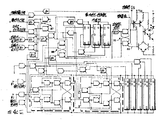
제1도는 본 방명의 일부 회로에 대한 블럭선도.1 is a block diagram of some circuits of the present invention.
제2도는 본 발명을 포함하는 스테레오픈 수신기에 대한 블럭선도.2 is a block diagram of a stereophonic receiver incorporating the present invention.
제3도는 제1도의 보호 회로와 협력하는 스테레오 존재톤 검출기에 대한 블럭선도.3 is a block diagram of a stereo presence tone detector cooperative with the protection circuit of FIG.
제4a도, 제4b도 및 제4c도는 제3도의 블럭선도에 대한 개략적 논리선도.4A, 4B, and 4C are schematic logic diagrams for the block diagram of FIG.
제5도는 두필터의 특성 곡선도.5 is a characteristic curve diagram of two filters.
* 도면의 주요부분에 대한 부호의 설명* Explanation of symbols for main parts of the drawings
12 : 저역통과필터 16 : 피크 레벨감지기12
18 : 타이밍 회로 42 : 모노 및 스테레오 모드 스위치18: timing circuit 42: mono and stereo mode switch
44 : 파이로트 톤 검출기44: pilot tone detector
본 발명은 AM스테레오 퇴 검출 부야에 관한 것이며 특히, 혼신을 수신함으로써 발생되는 스테레오톤 검출기 및 다른 스테레오 수신기 회로의 오동작이나 또는 불만족스러운 작동을 방지하는 것에 관한 것이다.FIELD OF THE INVENTION The present invention relates to an AM stereo regression detection field, and more particularly to preventing malfunction or unsatisfactory operation of stereotone detectors and other stereo receiver circuits caused by receiving interference.
청취되는 주파수와 동일한 주파수에서 다른 송신기로 인해 발생되는 혼신과 같은 공통채널 혼신은 방송분야에서 잘 알려져 있다. 이와같은 혼신은 두 오디오 신호가 동시에 틀린다는 점에서 모노픈 수신기의 문제점이 될 수 있다. 이러한 사실은 AM스테레오 수신기에서 또다른 문제점을 야기시킨다. 몇몇 스테레오 수신기에서, 위상 로크루프(PLL)는 위상 변조형 반송파(RF 혹은 IF)로부터 코사인 정정 신호를 유도하는데 이용된다. 또다른 수신기에서, PLL은 스테레오 복조 처리과정에서 스테레오 프로그램의 좌측 및 우측 신호용 스테레오폰 오디오 출력 신호 L 및 R을 제공하는데 사용된다. 코사인 정정 신호의 경우에 있어서, 공통 채널 혼신을 미세한 정도의 왜곡을 야기시키지만, L 및 R의 복조에 대해서는 신호원을 측면에서 측면으로 이동되게 하는 영향을 미친다. 스테레오폰 송신이 일어나고 있음을 나타내는 신호가 예를들면 2 내지 25Hz의 초 저주파수톤이며, 공통 채널 혼신은 스테레오 신호가 수신되지 않을 때 잘못된 스테레오 검출 신호를 발생시킨다. 이와같은 검출신호는 스테레오 표시광으로 스테레오의 발생을 표시할 뿐만 아니라, 스테레오 작동 모드로 작동할 수 있게 하는등 바람직하지 못한 영향을 미친다. 부가된 스테레 오톤을 구비한 스테레오폰 신호가 공통 채널 혼신이 발생할 때 수신되며, 수신기는 스테레오로 유지되지만 신호원의 동작이 명백히 감지된다. 따라서, 공통 채널 혼신이 심각해지면 스테레오 모드로 작동할 수 없게 하는 것이 바람직하다. 몇가지 방송 상태에서, 인접한 채널 혼신도 또한 문제가 되며, 이로 인해 모노폰 모드가 더 바람직할 수도 있다.Common channel interference, such as interference caused by other transmitters at the same frequency as is heard, is well known in the broadcast art. This interference can be a problem for monophonic receivers in that both audio signals are wrong at the same time. This fact causes another problem in AM stereo receivers. In some stereo receivers, phase lock loop (PLL) is used to derive cosine correction signals from phase modulated carriers (RF or IF). In another receiver, the PLL is used to provide the stereophone audio output signals L and R for the left and right signals of the stereo program in the stereo demodulation process. In the case of cosine correction signals, common channel interference causes a slight degree of distortion, but for L and R demodulation, the signal source is moved from side to side. A signal indicating that stereophone transmission is taking place is, for example, an ultra low frequency tone of 2 to 25 Hz, and common channel interference generates false stereo detection signals when no stereo signal is received. Such a detection signal not only indicates the occurrence of stereo with stereo display light, but also has an undesirable effect such as being able to operate in the stereo operation mode. Stereophone signals with added stereo tones are received when common channel interference occurs and the receiver remains in stereo but the signal source's operation is clearly detected. Therefore, it is desirable to be unable to operate in stereo mode if the common channel interference is severe. In some broadcast conditions, adjacent channel interference is also a problem, so monophone mode may be more desirable.
본 발명의 목적은 공통 채널 혹은 인접체널의 혼신이 AM스테레오 방송 수신에 심각한 영향을 미치는 것을 방지하는 것이다.An object of the present invention is to prevent the interference of the common channel or the adjacent channel has a serious effect on AM stereo broadcast reception.
본 발명의 특수 목적은 아무것도 수신되지 않을때 스테레오폰 신호가 나타나는 것을 방지하는 것이다.It is a special object of the present invention to prevent the stereophone signal from appearing when nothing is received.
본 발명의 또 다른 특수목적은 혼신이 신호원의 감지된 간격이나 위치에 영향을 미치는 것을 방지하는 것이다.Another special object of the present invention is to prevent interference from affecting the sensed spacing or position of the signal source.
본 발명의 또 다른 목적은 모노폰 송신만이 수신될때 혼신으로 인하여 수신기에서 스테레오 모드로 작동하게 되는 것을 방지하는 것이다. 이와 같은 목적이나 또다른 목적이 본 발명에 따른 회로에 의해서 이루어지며, 이 회로에서 인입 신호(RF 혹은 IF)나 또는 상기 인입 신호의 일부는 공통 채널 혼신으로 인하여 발생되는 초 저주파만을 통과시키도록 여파된다. 이때 필터 출력이 검사되고, 만약 주어진 레벨에서 나타나는 신호가 있으면 모노폰 모드 작동이 가능하며, 다시말하면 스테레오 톤 검출기, 정정회로 및 스테레오 모드 스위치는 짧은 시간동안 작동하지 않는다. 부가된 톤을 갖는 스테레오폰 송신이 수신되면, 고레벨의 필터 출력 신호는 톤 검출기가 작동되지 않게 해야 한다. 인접 채널 혼신이 문제시 되면 고역 통과 필터가 사용되며, 고역 통과 필터의 출력은 작동모드를 제어한다.Another object of the present invention is to prevent the receiver from operating in stereo mode due to interference when only monophone transmissions are received. This or another object is achieved by a circuit according to the invention in which the incoming signal (RF or IF) or part of the incoming signal passes only the ultra-low frequencies generated by common channel interference. do. The filter output is then checked and monophone mode operation is possible if there is a signal present at a given level, ie the stereo tone detector, correction circuitry and the stereo mode switch will not operate for a short time. When a stereophone transmission with an added tone is received, the high level filter output signal should cause the tone detector to be inoperative. If adjacent channel interference is a concern, a high pass filter is used, and the output of the high pass filter controls the operating mode.
제1도는 본 발명에 대한 간략한 블럭선도이며, 스테레오 수신기(제2도)의 S-R채널로부터 인입하는 입력 신호를 제공하는 입력 단자(10)를 도시한 것이다. AM스테레오폰 시스템의 두 채널은 I(동상 변조 또는 포락선 변조용)와, Q(직각 변조 또는 위상변조용)로 불리우며, I는 일반적으로 모노폰 또는 1+L+R변조를 나타내며 Q는 차 신호 L-R의 기능을 나타낸다.FIG. 1 is a simplified block diagram of the present invention and shows an
Q신호는 저역 통과 필터(12)에서 여파된다. 상기 저역 통과 필터의 출력은 혼신이 나타날때 조차도 매우 작으며, 증포기(14)에 결합된다. 증폭기 다음단에는 예정된 레벨의 출력이 검출될때 출력 신호를 제공하는 피크 레벨 감지기(16)가 연결된다. 예정된 레벨은 제4도에 따라서 설명될 서로 다른 수신 신호 특성에 따라서 변화한다. 레벨 감지기의 출력 신호는 타이밍 회로(18)를 활성화 시킨다. 타이밍 회로는 스테레오 수신기의 스테레오톤 검출 회로내의 회로이개나 또는 정정 회로의 일부일 수도 있다. 제3도에 따라서 설명되는 바와 같이 정정회로(24)는 단지 검출기를 저속 모드로 리세트 시키는 톤검출기에 신호를 연결시키는 작용을 할 뿐이다. 저속작동 모드에서 검출기가 부여된 기간동안 스테레오 톤 검출신호를 공급할 수 없으면, 이와 같은 장치는 레벨검출회로 다음단의 분리된 타이머와 같다.The Q signal is filtered by the
제2도는 제1도의 회로를 나타낸는 정정 회로(24)를 부가한, 미합중국 특허원 제 4,159,398에 따른 AM스테레오폰 수신기에 대한 블럭선도이다. 이 수신기는 본 발명을 이용한 수신기중 하나일 뿐이며, 수신기와 수신기를 작동시키도록 의도된 신호는 어느것도 본 발명을 제한하도록 구성된 것은 아니다.FIG. 2 is a block diagram of an AM stereophone receiver according to US Patent Application No. 4,159,398 with the addition of a correction circuit 24 showing the circuit of FIG. This receiver is only one of the receivers using the present invention, and neither the receiver nor the signal intended to operate the receiver is configured to limit the present invention.
제2도의 수신기는(1+L+R) cos(![]()
![]()
![]()
![]()
![]()
![]()
![]()
![]()
![]()
![]()
![]()
![]()
sin![]()
![]()
![]()
![]()
![]()
![]()
![]()
![]()
![]()
![]()
![]()
![]()
![]()
![]()
![]()
![]()
![]()
![]()
본 발명에 의한 회로(24)는 L-R검출기(30)의 출력에 연결되거나 또는, 본 발명의 특수 적용시 자동 이득 제어 (AGC)된 L-R신호에 인가된다. 또다른 실시예에서, 포락선 신호가 1+L+R신호는 보호 회로를 활성화 시키는데 사용될 수 있다.The circuit 24 according to the present invention is connected to the output of the
제3도에서 블럭선도 형태로 도시된 톤 검출기 회로(44)는 본 발명의 양수인에게 양도된 공도 계류중인 미국 특허원 제262,839호에서 채택된다. 필터(50)의 입력신호는 설명된 바와 같이 L-R-ST이다. 필터(50)는 가령 25Hz와 같은 스테레오(ST)주파수나 파이로트 톤 주파수에 중심점이 있다. 필터(50)의 출력은 두 비교기(52),(54)에 분리되어 연결된다. 비교기(52)의 출력은 래치 L1의 세트 입력에 연결된다. 래치 L1의 리세트입력과, 시프트 레지스터(58)의 클리어 입력에 연결된다. 비교기(54)의 출력은 래치 L1의 리세트입력과, 시프트 레지스터(58)의 데이타 입력에 연결되며, 이와 같은 상호 연결에는 만약 필요하다면 지연 장치(59)를 개재한다. 시프트레지스터(58)출력은 두 논리 게이트 즉 AND게이트(60) 및 NOR게이트(62)에 병렬로 연결된다. 단순화하기 위하여 레지스터(58)의 세 출력 단자 Q0, Q1, O2가 도시되어 있지만 희방하는 수효의 출력이 사용될 수도 있다. 레지스터(58)의 Q2출력은 래치 L2의 리세트 입력에 연결된다. AMD게이트(60)출력은 래치L3의 세트입력에 연결되고, NOR게이트(62)의 한 출력은 래치 L3의 리세트 입력에 연결된다. 래치 L3출력은 AND게이트(64)에 연결된다. NOR게이트(62) 다른 출력은 반전기(66)를 통하여, 한 입력이 래치L2의 출력인 OR게이트(68)의 다른 입력에 연결된다. 래치 L1내지 L3은 모토로라 14043B와 같은 쿼드러쳐 NOR R-S래치에 의하여 실행된다. 시프트 레지스터(58)는 모토로라 MC14015와 같은 이중 4비트의 스태틱 스프트 레지스터에 의해 실행된다. 시프트 레지스터(58)의 리세트와 래치 L2의 세트는 동조되는 동안 톤검출기 회로를 유지 상태로 하기 위하여, 입력 단자(70)를 경유하여 아웃 오브 로크(out-of-lock) 검출기와 같은 외부 회로(도시 안됨)에 연결된다. OR게이트(68)의 출력은 모토로라 MC1555와 같은 타이밍 회로(72)의 트리거 입력 및 리세트 입력에 연결된다. 전형적인 시간 지연은 750ms이다. 타이밍 회로의 출력은 반전기(74)를 경우하여 AND게이트(64)의 제2입력에 연결되며, 게이트(64)의 출력은 단자(76)에서 이용될 수 있다. 대역통과필터(50)에 입력된 신호는 많은 주파수로 구성되지만, 필터 출력 신호는 필터 회로의 설계에 따라 변화하는 사인파이다. 최대 진폭도 물론 변화하며, 단기간동안 0으로 될 수 있다. 비교기(52)(54)는 다른 임계치 레벨을 갖는다. 비교기(52)의 임계치는 비교기가 영점교차 검출기로서의 기능을 하도록 영이나 또는 그 근방의 값을 가질 수 있다. 톤 주파수나 그 근방의 주파수에서 비교기(52)를 트리거 시키기에 충분한 외부 신호가 있으므로 비교기의 출력은 톤 주파수에서 상당히 규칙적인 구형파이다. 비교기(52)의 출력신호는 래치 L1의 리세트 신호로 사용될 뿐만 아니라 시프트 레지스터(58)의 클럭 입력 신호로도 사용 된다. 비교기(54)의 임계치는 한 신호의 예상 프크 진폭보다 조금 낮은 점에서 세트되며, 비교기(54)의 출력 펄스는 비교기(52)의 출력 펄스보다 좁다. 이때 래치 L1은 비교기(54) 출력에 의해 세트되고 비교기(52)출력에 의해 리세트된다. 래치 L1의 출력은 시프트 레지스터(58)의 데이타 입력에 연결된다. 적절한 주파수 및 진폭을 갖는 신호를 처음 검출하는데 있어서, 래치 L1에서부터 시프트 레지스터(58)의 출력에 논리 1이 연결되고, 클럭 인(clock-in)될 때 레지스터(58)의 Q0출력에 논리 1이 나타나서 병렬 출력은 0-0-1이 된다. 연속적으로 제2 및 제3검출을 할때 레지스터 출력은 각각 0-1-1 및 1-1-1이된다. 제3검출시 AND게이트(60)의 모든 입력이 논리 1이므로 래치 L3의 세트 입력에는 논리 1이 연결되고 래치 입력은 논리 1이된다. 래치 L3은 래치된 후, 한 주기의 톤 신호가 없거나 어떤 값보다 너무 낮으면 레지스터(58)의 출력은 1-1-0이 되지만 래치 L3은 래치된 상태. 머무를 것이다. 세 펄스가 없거나 너무 낮으면 시프트 레지스터 출력은 0-0-0이 될 것이다. 시프트 레지스터의 출력이 NOR게이트(62) 입력이기도 하므로 NOR게이트는 논리 1을 출력하며, 래치 L3을 리세트 시키고 래치L3의 출력이 0으로 되게 한다. 이때 세 연속사이클이 필터(50)의 출력 신호에서 검출될때까지 래치 출력은 논리 0 상태에서 머문다. 단자(70)로부터의 아웃 오브 로크 신호는 래치 L2의 세트 입력에도 연결되며, 레지스터(58)의 Q2출력은 리세트 입력에 연결된다. Q2에 논리 1이 나타나면 래치 L2의 출력은 논리 0으로 되며, 논리 0 상태에서 머문다. 상기 래치의 한 출력 신호에서 일련의 0이 나타나서 레지스터(58)에 기록되어, NOR게이트(62)의 출력이 논리 1로 되면, 반전기(6)에서 출력되는 OR게이트(68)의 제2 입력신호는 타이밍 회로(72)의 트리거 및 리세트상에 하강파형을 형성시킨다. 상기 하강 파형은 타이밍 주기를 시작하고, AND게이트(64)의 한 입력을 0 상태로 만든다. 이때 단자(76)의 출력은 0 신호이거나 무파이로트 톤 신호이다.The tone detector circuit 44, shown in block diagram form in FIG. 3, is employed in highway pending US Patent Application No. 262,839, assigned to the assignee of the present invention. The input signal of the
상기 타이밍 주기동안, 또다른 논리 1이 시프트 레지스터(58)를 통해 이동되고 그 다름 일련의 0이 이어지면, 타이밍 회로(72)는 OR게이트(68)로부터의 또다른 하강 파형에 의해서 제2 타이밍 주기동안 리세트 된다. 시프트 레지스터(58)가 이어서 논리 1로 채워지고 래치 L3를 논리 1상태로 세트시킨다 할지라도, 제2 타이밍 주기가 끝날때까지 단자(76)에서 출검 신호는 발생되지 않는다. 따라서 매우 잡음이 많은 신호를 수신하는 동안 파이로트 검출기의 오동작이 방지된다.During this timing period, if another logic one is moved through the shift register 58 and the other series of zeros follows, the
종래 기술에 의한 제3도의 톤 검출기 회로에 정정 회로(24)를 부가한 상태에서, OR 게이트(78)는 시프트 레지스터(58)의 리세트 입력에 삽입된다. OR게이트(78)의 제2입력은 정정 회로(24)에서 비롯된 것이며, 따라서 심각한 정도의 공통 채널 혼신 발생을 나타낸는 회로(24)의 출력은 시프트 레지스터(58)를 리세트 시키고, 단자(76)에서 출력은 "스테레오 신호가 나타나지 않음" 이 된다.With the correction circuit 24 added to the tone detector circuit of FIG. 3 according to the prior art, the OR gate 78 is inserted into the reset input of the shift register 58. As shown in FIG. The second input of the OR gate 78 comes from the correction circuit 24, so that the output of the circuit 24, which indicates a significant degree of common channel interference, resets the shift register 58, and the terminal 76 The output at will be "no stereo signal."
제3도의 톤 검출기 회로는 본 발명에 의한 정정 장치 회로를 이용하는 톤 검출기 회로중의 하나일 뿐이며 톤 검출기 회로에 대해 제한하려는 것은 것이다.The tone detector circuit of FIG. 3 is only one of the tone detector circuits using the correction device circuit according to the present invention and is intended to be limited to the tone detector circuit.
제4a도, 제4b도 및 제4c도는 본 발명을 포함하는AM스테레오 수신기의 회로 부분에 대한 개략적인 논리선도이다. 제4a도는 톤 검출기(44)의 대역 통과 필터(50)와 정정회로(24)를 포함한다. 입력 단자(80)의 신호는 Q 또는 차 신호(L-R)COS![]()
![]()
![]()
![]()
Q신호는 파이로트 톤 검출기(44)용 파이로트 톤이나 스테레오 존재톤과 관련된 출력을 공급하기 위해 대역통과 필터(50)에서 여파된다. 양호한 실시예에서, 서로 다른 두 진폭 레벨에서 톤 검출에 응답하여 신호를 공급하는 두 출력(#1),(#2)이 있다. 출력(#1)을 톤 검출기에 공급하는 회로는 영점 교차 검출기이며, 출력(#2)을 공급하는 회로는 고레벨 톤 검출기이다. 이와 같은 기능은 위에서 언급된 공동 계류중인 출원서에서 더 설명딘다. 저역 통과 필터(12)는 증폭기(14)에 연결되며, 단자(84)의 신호는 공통 채널 증폭기(14)에서 증폭되어, 증폭기로부터 인입하는 톤 검출기의 입력#1), (#2)에 적절한 레벨로 연결된다.The Q signal is filtered out of the
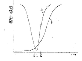
제5도는 선도에 의하면, 두 필터(50),(12)의 상보적기능은 수신기 회로를 높은수준으로 보호하는 것이다. 이러한 선도에서 곡선 A는 대역 통과 필터(50)의 감쇠를 나타낸다. 곡선 B는 저역 통과 필터(12)의 특성을 나타낸다. 대역 통과 필터는 점C로 나타내진 예상된 톤 신호의 주파수 (양호한 예로는 25Hz)에 중심이 있다. 두 곡선 A 및 곡선 B의 특성은 신호가 잘못 검출되는 것을 방지하는 것이며, 회로내의 파이로트 톤필터인 대역 통과 필터(50)만을 사용하면, 25Hz톤 보다 매우 높거나 매우 낮은 주파수에서의 매우 강한 신호가 잘못된 검출을 야기시킬 수 있다. 저역 통과 필터를 부가함으로써 점 D보다 낮은 주파수나 점 E보다 높은 주파수에서의 신호는 잘못된 검출을 야기시킬 수 없다. 점 D와 점 E사이의 윈도우에서, 만약 파이로트 톤 검출기(44)가 맞거나 틀리게 검출된 톤이 오랜 기간동안 예를들면, 스테레오 검출 신호가 출력되기 전 2초간 지속될 것을 요구하지 않는다면 혼신 비트는 잘못된 검출을 야기시킬 수도 있다. 따라서 오검출신호가 발생하기란 거의 불가능하다.5 shows, according to the diagram, the complementary function of the two
제4c도는 제3도에서 블럭형태로 도시된 톤 검출기의 대부분에 양호한 실시예를 도시한 것이다. 제4a도, 제4b도 및 제4c도는 톤 검출기의 I2L실시예이며 반면에 제3도의 블럭선도는 CMO실시예를 기초로 한 것이다. 그런, 상기 두 실시예는 넓은 의미에서 등가의 것이다. 제4C도의 톤 검출기의 한 입력은 레벨 검출기회로(도시안됨)로부터 인입되는 레벨 검출 신호이며 Q신호의 진폭값이다. 클리어 신호는 상기의 묵음화 신호로부터 파생된다. 아웃 오브 로크 신호는 제3도의 단자(70)의 신호이며 희방된 채널의 동조치이다. 증폭기의 게이트(#1) 및 증폭기의 게이트(#2)의 신호는 제4b도에 도시된 바와 같은 공통 채널 증폭기(14)로부터 파생된다. 게이트(#1)는 통상적으로 작동하는 낮은 트립(trip)레벨을 구성하며, 게이트(#2)는 높은 트립 레벨을 구성한다. 게이트(#1)는 게이트(#3)에 연결되고, 게이트(#3)는 톤 검출이 있을때 파이로트 래치(86)로부터 활성활 되는 게이트(#4)를 경우하는 신호에 의해 차례로 차된되며, 따라서 낮은 임계치 게이트 결합을 방지한다. 게이트(#5)가 클리어 입력단의 저 입력에 의해서 고 상태로 되면, 래치(87)는 저 상태로 되고, 톤 검출기가 쇼트 카운트(short count)모드로 작동하게 만든다. 롱 카운트 인히비트(long count inhibit)신호는 게이트(#6)에 연결되며, 래치(88)로부터의 제2입력 신호도 또한 1이면 파이로트 래치(86)는 리세트될 것이다. 래치(86)의 출력은 제2도의 스테레오 디코더(41)에 다시 연결된다. 래치(88)의 입력은 시프트 레지스터로부터의 전체 Q의 합성이며, 이 실시예에서 정체 Q는 7개의 구분(segment)을 갖는 것으로 이해된다. 시프트 레지스터의 각각 래치회로 또는 플립플롭 회로는 적절한 레벨의 한 사이클의 스테레오톤 신호에 응답하여 고 상태로 된다. 게이트(#7)의 출력이 고 상태로 되면, 이와 같은 고 상태는 시프트 레지스터의 제1부분의 리세트를 1 상태로 만들며, 게이트(#8)를 통하여 시프트 레지스터의 제2부분의 세트입력을 0 상태로 만든다. 시프트 레지스터는 짧은 작동 모드에서 검출이 발생하도록 하기 위해 0. 레지스터를 클럭아웃(clock out)할 때까지 대기해야 한다. 시프트 레지스터의 일련의 모든 0이 긴 작동 모드를 개시하는 것을 방지하기 위하여 1이 더해진다. 파이로트 톤이 있으면, 일련의 1이 시프트 레지스터를 통하여 클럭될 것이며, 모든 Q가 고 상태이면 게이트(#9)의 입력은 고 상태일 것이고 출력은 저 상태일 것이며, 게이트(#10)(래치(86)의 입력에 연결됨)로 출력되는 플립플롭(88)의 출력은 고 상태일 것이다. 이와 같은 조건하에서 플립플롭(87)의 출력은 고 상태일 것이고, 게이트(#10)는 래치(86)에 저상태를 출력할 것이다. 이때 파이로트 래치(86)는 리세트되고 래치의 출력(89)은 LED(90)용 제어 회로를 활성화 시킬 것이며, 스테레오 표시기(46)가 켜질 것이다.FIG. 4C shows a preferred embodiment of most of the tone detectors shown in block form in FIG. 4A, 4B and 4C are the I 2 L embodiment of the tone detector, while the block diagram of FIG. 3 is based on the CMO embodiment. As such, the two embodiments are equivalent in a broad sense. One input of the tone detector of FIG. 4C is a level detection signal drawn from the level detector circuit (not shown) and is an amplitude value of the Q signal. The clear signal is derived from the silent signal above. The out of lock signal is a signal of the terminal 70 of FIG. 3 and is a tuning of the diluted channel. The signals of gate # 1 of amplifier and gate # 2 of amplifier are derived from common channel amplifier 14 as shown in FIG. 4B. Gate # 1 constitutes a low trip level that normally operates, while gate # 2 constitutes a high trip level. The gate # 1 is connected to the gate # 3, and the gate # 3 is sequentially ordered by a signal for the gate # 4 which is activated from the pilot latch 86 when there is a tone detection, Thus, low threshold gate coupling is prevented. When
이상에서 설명된 바와 같이, AM스테레오 수신기용 보호 회로가 도시되고 설명되었으며, 상기 AM스테레오 수신기는 스테레오폰형 오디오 정보뿐만 아니라, 스테레오폰형 정보의 존재 여부를 표시하는 예정된 초 저주파 톤 도포함하고 공통 채널 또는 인접 채널 혼신과 같은 혼신을 포함할 수도 있는 신호를 수신하기 위한 수단을 포함한다. 보호회로는 수신된 초 저주파 톤의 존재 여부와 특성에 의해 여러가지 수신기 기능을 제어할 뿐만 아니라, 수신된 혼신의 크기에 따라서도 그러한 기능을 제어한다.As described above, a protection circuit for an AM stereo receiver is shown and described, wherein the AM stereo receiver includes not only stereophonic audio information, but also a predetermined ultra low frequency tone indicating whether stereophonic information is present and a common channel or Means for receiving a signal that may include interference such as adjacent channel interference. The protection circuit not only controls various receiver functions by the presence and nature of received ultra low frequency tones, but also controls them according to the size of the received interference.
따라서 잘못된 스테레오 검출 신호 및 스테오오 표시가 방지되며, 적절한 신호가 수신되지 않을때 스데레오폰 모드는 작동하지 않을 것이고, 왜곡 정정 회로는 이와같은 상태하에서 작동하지 않을 것이다. 본 발명에 대한 다른 변형 및 변경이 가능하며, 이러한 변형 및 변경은 첨부된 특허청구범위의 정신과 범위내에 속하는 모든것을 커버할 수 있어야 한다.Thus, erroneous stereo detection signals and stereo indications are prevented, and the stereophone mode will not operate when the proper signal is not received, and the distortion correction circuit will not operate under such conditions. Other variations and modifications of the present invention are possible, and such variations and modifications should be able to cover all that falls within the spirit and scope of the appended claims.
Claims (6)
Applications Claiming Priority (2)
| Application Number | Priority Date | Filing Date | Title |
|---|---|---|---|
| US06/386,374 US4489431A (en) | 1982-06-08 | 1982-06-08 | Signal interference protection circuit for AM stereo receiver |
| US386,374 | 1982-06-08 |
Publications (2)
| Publication Number | Publication Date |
|---|---|
| KR840005289A KR840005289A (en) | 1984-11-05 |
| KR860001325B1 true KR860001325B1 (en) | 1986-09-13 |
Family
ID=23525326
Family Applications (1)
| Application Number | Title | Priority Date | Filing Date |
|---|---|---|---|
| KR1019830002528A KR860001325B1 (en) | 1982-06-08 | 1983-06-07 | Signal interference protection circuit for am stereo receiver |
Country Status (11)
| Country | Link |
|---|---|
| US (1) | US4489431A (en) |
| EP (1) | EP0110994B1 (en) |
| JP (1) | JPS59500795A (en) |
| KR (1) | KR860001325B1 (en) |
| BR (1) | BR8307398A (en) |
| CA (1) | CA1196387A (en) |
| DE (1) | DE3379373D1 (en) |
| HK (1) | HK25692A (en) |
| MX (1) | MX152521A (en) |
| SG (1) | SG17692G (en) |
| WO (1) | WO1983004459A1 (en) |
Families Citing this family (8)
| Publication number | Priority date | Publication date | Assignee | Title |
|---|---|---|---|---|
| US4716590A (en) * | 1984-01-17 | 1987-12-29 | Sansui Electric Co., Ltd. | AM stereo transmission method and apparatus |
| US4653095A (en) * | 1986-02-06 | 1987-03-24 | Kahn Leonard R | AM stereo receivers having platform motion protection |
| US5008939A (en) * | 1989-07-28 | 1991-04-16 | Bose Corporation | AM noise reducing |
| US5151939A (en) * | 1990-03-21 | 1992-09-29 | Delco Electronics Corporation | Adaptive audio processor for am stereo signals |
| DE69228624T2 (en) | 1991-04-18 | 1999-07-29 | Bose Corp | Reduction of audible noise with stereo reception |
| DE19630392C2 (en) * | 1996-07-26 | 1998-10-01 | Sgs Thomson Microelectronics | Stereo decoder with smooth transition between stereo operation and mono operation |
| US6570500B1 (en) * | 2001-11-09 | 2003-05-27 | Nokia Corporation | Infra-sound surveillance system |
| US8144878B2 (en) | 2006-03-06 | 2012-03-27 | Mediatek Inc. | FM receiver and pilot detector thereof, and method for determining a type of a processed signal |
Family Cites Families (9)
| Publication number | Priority date | Publication date | Assignee | Title |
|---|---|---|---|---|
| US3944749A (en) * | 1972-05-10 | 1976-03-16 | Kahn Leonard R | Compatible AM stereophonic receivers involving sideband separation at IF frequency |
| US4192970A (en) * | 1977-01-31 | 1980-03-11 | Kahn Leonard R | Reduction of adjacent channel interference |
| US4332978A (en) * | 1977-03-21 | 1982-06-01 | The Magnavox Consumer Electronics Co. | Low frequency AM stereophonic broadcast and receiving apparatus |
| US4159398A (en) * | 1977-09-27 | 1979-06-26 | Motorola, Inc. | Stereo presence signal for an AM stereo system |
| US4169968A (en) * | 1978-01-27 | 1979-10-02 | Motorola, Inc. | Noise protection circuit for am stereo cosine correction factor |
| JPS5735440A (en) * | 1980-08-12 | 1982-02-26 | Sony Corp | Mode switching controller for am stereo receiver |
| JPS5780842A (en) * | 1980-11-07 | 1982-05-20 | Matsushita Electric Ind Co Ltd | Pilot signal detecting device |
| US4379208A (en) * | 1980-11-13 | 1983-04-05 | National Semiconductor Corporation | AM Stereo receiver logic |
| US4368356A (en) * | 1981-03-20 | 1983-01-11 | Motorola Inc. | Pilot tone detector utilizing phase deviation signals |
-
1982
- 1982-06-08 US US06/386,374 patent/US4489431A/en not_active Expired - Lifetime
-
1983
- 1983-05-30 MX MX197468A patent/MX152521A/en unknown
- 1983-06-07 CA CA000429897A patent/CA1196387A/en not_active Expired
- 1983-06-07 KR KR1019830002528A patent/KR860001325B1/en not_active IP Right Cessation
- 1983-06-07 JP JP58502439A patent/JPS59500795A/en active Granted
- 1983-06-07 DE DE8383902350T patent/DE3379373D1/en not_active Expired
- 1983-06-07 BR BR8307398A patent/BR8307398A/en not_active IP Right Cessation
- 1983-06-07 WO PCT/US1983/000906 patent/WO1983004459A1/en active IP Right Grant
- 1983-06-07 EP EP83902350A patent/EP0110994B1/en not_active Expired
-
1992
- 1992-02-24 SG SG176/92A patent/SG17692G/en unknown
- 1992-04-09 HK HK256/92A patent/HK25692A/en not_active IP Right Cessation
Also Published As
| Publication number | Publication date |
|---|---|
| BR8307398A (en) | 1984-05-08 |
| EP0110994A1 (en) | 1984-06-20 |
| US4489431A (en) | 1984-12-18 |
| WO1983004459A1 (en) | 1983-12-22 |
| SG17692G (en) | 1992-04-16 |
| CA1196387A (en) | 1985-11-05 |
| MX152521A (en) | 1985-08-14 |
| JPS59500795A (en) | 1984-05-04 |
| EP0110994B1 (en) | 1989-03-08 |
| EP0110994A4 (en) | 1985-09-16 |
| KR840005289A (en) | 1984-11-05 |
| JPH02903B2 (en) | 1990-01-09 |
| DE3379373D1 (en) | 1989-04-13 |
| HK25692A (en) | 1992-04-16 |
Similar Documents
| Publication | Publication Date | Title |
|---|---|---|
| US5222253A (en) | Transient suppression circuit for a time domain duplex transceiver | |
| KR860001325B1 (en) | Signal interference protection circuit for am stereo receiver | |
| GB1480774A (en) | Radio receivers | |
| US5261004A (en) | Noise blanking circuit for AM stero | |
| EP0998084B1 (en) | Phase-shift-keying demodulator and demodulation method using a period-width windowing technique | |
| CA1171139A (en) | Dual mode tone detector circuit | |
| KR880000649B1 (en) | Multiple tone pirot signal system | |
| US5675614A (en) | Digital squelch circuit | |
| US4821322A (en) | FM multiplex decoding | |
| US4405837A (en) | Tone detector circuit | |
| US4447909A (en) | Circuit for rapid recognition of FSK signals in a radio channel | |
| US4661996A (en) | Method and apparatus for indicating radio frequency carrier loss in remotely controlled vehicles | |
| US4171516A (en) | Tone phase shift detector | |
| US3902122A (en) | Apparatus for speeding-up the attack time of a tone-coded radio receiver | |
| US5359661A (en) | Out-of-lock detector for synchronous AM detection | |
| US4982431A (en) | Signal distinction circuit | |
| US7133468B2 (en) | Concurrent FM signal receiver | |
| KR810002133B1 (en) | Noise cancelling system for fm receiver | |
| JPS5720047A (en) | Am stereophonic receiver | |
| JPS6333813B2 (en) | ||
| JPH0669896A (en) | Signal presence/absence discriminating circuit | |
| JPS62260417A (en) | Receiver | |
| JPS6053990B2 (en) | TV audio multiplex broadcast receiver | |
| JPH0720765U (en) | TV receiver channel selection device | |
| JPS6159592B2 (en) |
Legal Events
| Date | Code | Title | Description |
|---|---|---|---|
| A201 | Request for examination | ||
| E902 | Notification of reason for refusal | ||
| G160 | Decision to publish patent application | ||
| E701 | Decision to grant or registration of patent right | ||
| GRNT | Written decision to grant | ||
| FPAY | Annual fee payment |
Payment date: 20020726 Year of fee payment: 17 |
|
| EXPY | Expiration of term |