KR860001242B1 - Current control apparatus for electric power systems - Google Patents

Current control apparatus for electric power systems Download PDF

Info

Publication number
KR860001242B1
KR860001242B1 KR1019830002248A KR830002248A KR860001242B1 KR 860001242 B1 KR860001242 B1 KR 860001242B1 KR 1019830002248 A KR1019830002248 A KR 1019830002248A KR 830002248 A KR830002248 A KR 830002248A KR 860001242 B1 KR860001242 B1 KR 860001242B1
Authority
KR
South Korea
Prior art keywords
current
value
voltage
phase
vector
Prior art date
Application number
KR1019830002248A
Other languages
Korean (ko)
Other versions
KR840004631A (en
Inventor
켄이찌 오오즈끼
타께오 시마무라
Original Assignee
가부시기 가이샤 도시바
사바 쇼오이찌
Priority date (The priority date is an assumption and is not a legal conclusion. Google has not performed a legal analysis and makes no representation as to the accuracy of the date listed.)
Filing date
Publication date
Application filed by 가부시기 가이샤 도시바, 사바 쇼오이찌 filed Critical 가부시기 가이샤 도시바
Publication of KR840004631A publication Critical patent/KR840004631A/en
Application granted granted Critical
Publication of KR860001242B1 publication Critical patent/KR860001242B1/en

Links

Images

Classifications

    • HELECTRICITY
    • H02GENERATION; CONVERSION OR DISTRIBUTION OF ELECTRIC POWER
    • H02MAPPARATUS FOR CONVERSION BETWEEN AC AND AC, BETWEEN AC AND DC, OR BETWEEN DC AND DC, AND FOR USE WITH MAINS OR SIMILAR POWER SUPPLY SYSTEMS; CONVERSION OF DC OR AC INPUT POWER INTO SURGE OUTPUT POWER; CONTROL OR REGULATION THEREOF
    • H02M7/00Conversion of ac power input into dc power output; Conversion of dc power input into ac power output
    • H02M7/42Conversion of dc power input into ac power output without possibility of reversal
    • H02M7/44Conversion of dc power input into ac power output without possibility of reversal by static converters
    • H02M7/48Conversion of dc power input into ac power output without possibility of reversal by static converters using discharge tubes with control electrode or semiconductor devices with control electrode
    • H02M7/505Conversion of dc power input into ac power output without possibility of reversal by static converters using discharge tubes with control electrode or semiconductor devices with control electrode using devices of a thyratron or thyristor type requiring extinguishing means
    • H02M7/515Conversion of dc power input into ac power output without possibility of reversal by static converters using discharge tubes with control electrode or semiconductor devices with control electrode using devices of a thyratron or thyristor type requiring extinguishing means using semiconductor devices only
    • H02M7/525Conversion of dc power input into ac power output without possibility of reversal by static converters using discharge tubes with control electrode or semiconductor devices with control electrode using devices of a thyratron or thyristor type requiring extinguishing means using semiconductor devices only with automatic control of output waveform or frequency
    • H02M7/527Conversion of dc power input into ac power output without possibility of reversal by static converters using discharge tubes with control electrode or semiconductor devices with control electrode using devices of a thyratron or thyristor type requiring extinguishing means using semiconductor devices only with automatic control of output waveform or frequency by pulse width modulation
    • H02M7/529Conversion of dc power input into ac power output without possibility of reversal by static converters using discharge tubes with control electrode or semiconductor devices with control electrode using devices of a thyratron or thyristor type requiring extinguishing means using semiconductor devices only with automatic control of output waveform or frequency by pulse width modulation using digital control

Abstract

The appts. uses a DC voltage feedback foop for closed control of a motor current amplitude and phase. The load currents, which are supplied by a cycloconverter, are detected by the sensors. A detector which receives a sensed signal from the sensors generates a DC phase error signal and a DC amplitude signal according to the load currents and the phase instruction. The amplitude instruction, amplitude signal, and phase error signal are applied to a comparator circuit. The comparator circuit generates two voltage instructions to a control circuit. The control circuit supplies the cycloconverter with voltage instruction.

Description

전력변화장치의 전류제어 방법Current Control Method of Power Change Device

제1도는 종래의 전류제어 방법을 채용한 전력변환 장치의 구성도.1 is a configuration diagram of a power conversion device employing a conventional current control method.

제2도는 다상 전류와 그 합성치인 전류 벡터와의 관계를 설명하기 위한 도면.2 is a diagram for explaining the relationship between a polyphase current and a current vector which is a composite value thereof.

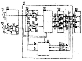
제3도는 본 발명의 전류제어 방법을 채용한 전력변 환장치의 구성도.3 is a configuration diagram of a power converter employing the current control method of the present invention.

제4도는 본 발명의 전류제어 방법을 설명하기 위한 각 신호의 관계도.4 is a relationship diagram of each signal for explaining the current control method of the present invention.

제5도는 제3도중의 검출기(450)의 상세도.5 is a detailed view of the detector 450 in FIG.

제6도는 제3도중의 제어회로(350)의 상세도.6 is a detailed view of the control circuit 350 in FIG.

제7도는 본 발명을 실시하여 유도 전동기를 벡터 제어로 운전할때의 블록도이다.7 is a block diagram when the induction motor is operated by vector control according to the present invention.

* 도면의 주요부분에 대한 부호의 설명* Explanation of symbols for main parts of the drawings

30 : 회전수설정기 31 : 벡터제어기30: rotation speed setter 31: vector controller

101 : 전류진폭설정기 103 : 주파수설제기101: current amplitude setter 103: frequency control device

150 : 지령기 20 : 전력변환장치150: commander 20: power converter

250,350 : 제어회로 450 : 검출기250,350: control circuit 450: detector

500 : 싸이크로콘버터 507-509 : 전류검출기500: micro-converter 507-509: current detector

600 : 부하 601 : 회전계600: load 601: tachometer

본 발명은 예를들어 전동기와 같은 부하에 대한 가변전압 가변주파수 전원으로서 적당한 인버터 또는 싸이크로콘버터와 같은 전력변환장치에 있어서, 다상 전류의 설정치 지령입력과 부하에 실제로 공급되는 다상전류와의 사이에 위상오차, 진폭오차가 생기지 않게하는 전력변환 장치의 전류제어 방법에 관한 것이다.The present invention is, for example, in a power converter such as an inverter or a microconverter suitable as a variable voltage variable frequency power source for a load such as an electric motor, between a setpoint command input of a polyphase current and a polyphase current actually supplied to a load. The present invention relates to a current control method of a power conversion device that prevents phase error and amplitude error.

인버터 또는 싸이크로콘버터와 같은 전력변환장치를 사용하여 부하에 가변 주파수의 전류를 공급하는 경우, 전력변환장치에 대한 전류 설정치와 부하 전류와의 사이에 위상 오차, 진폭오차가 생긴다는 것이 알려져 있다. 즉, 제1도는 종래의 싸이크로콘버터의 전류제어 구성도로서, 이것을 이용하여 종래의 전류제어법의 문제점을 설명한다. 이 도면은 부하에 싸이크로콘버터를 사용하여 3상 교류 전류를 공급하는 구성을 도시한 것으로(101)은 전류진폭 설정기로서 진폭지령치 Ⅰ1 *을 설정한다. (103)은 부하에 공급하는 교류 주파수의 설정기로서 출력 주파수에 상당하는 전압 Ⅴf1 *(주파수 지령)을 설정한다. (100)은 지령기로서 후술하는 전력 변환장치(10)로의 전류지령을 만들어 낸다. (105)는 계수기로서 진폭지령치 I1 *를 K1배한다. (106)은 전압/주파수 변환기로서, 주파수 지령치의 전압 Vf1 *을 입력하여 목적하는 출력주파수에 비례하는 펄스주파수 f1 *'를 발진한다. (109)는 카운터로서, 펄스주파수 f1 *'를 카운트하여 그 출력에서 출력주파수의 1주기로 일순하는 디지탈치의 신호

Figure kpo00001
을 입력하여 단위 정현파의 3상 전류지령
Figure kpo00002
을 발생한다. 즉
Figure kpo00003
는 식(1)로 표시된다.In the case of supplying a variable frequency current to a load by using a power converter such as an inverter or a micro-converter, it is known that a phase error and an amplitude error occur between the current set value of the power converter and the load current. That is, FIG. 1 is a configuration diagram of the current control of the conventional micro-converter, and the problems of the conventional current control method will be described using this. This figure shows a configuration in which a three-phase alternating current is supplied to the load using a micro-converter (101), which sets the amplitude command value I 1 * as a current amplitude setter. Numeral 103 sets the voltage V f1 * (frequency command) corresponding to the output frequency as a setter of the alternating frequency to be supplied to the load. Reference numeral 100 generates a current command to the power converter 10 described later as a commander. Numeral 105 denotes K 1 times the amplitude command value I 1 * . Reference numeral 106 denotes a voltage / frequency converter, which inputs the voltage V f1 * of the frequency command value to oscillate a pulse frequency f 1 * ′ proportional to the desired output frequency. 109 is a counter that is a digital value signal that counts the pulse frequency f 1 * ' and repeats it at one output cycle of the output frequency.
Figure kpo00001
3-phase current command of unit sine wave
Figure kpo00002
Occurs. In other words
Figure kpo00003
Is represented by equation (1).

Figure kpo00004
Figure kpo00004

그리고 이하의 설명에서 사용되는 제1도의 함수기(111)의 제5도의 함수기(454) 및 제6도의 함수기(368)등은 그 구성이 주지의 판독전용 메모리(소위 ROM)를 기본 요소로하고, 그 어드레스에 디지탈치의 입력이 주어지면 기억되어 있는 디지탈치의 함수치가 출력되고, 그 디지탈치의 함수치를 아나로그치로 고쳐서 출력하는 것을 사용할 수 있다. (116), (117), (118)은 곱셈기로서, 단위전류 지령치

Figure kpo00005
와 계수기(105)의 출력신호를 곱셈하여 교류전류 지령치
Figure kpo00006
를 만든다. 즉
Figure kpo00007
는 식(2)로 표시된다.In addition, the functional device 454 of FIG. 5 and the functional device 368 of FIG. 6 of FIG. 1 and the functional device 111 of FIG. 1 used in the following description are based on the well-known read-only memory (so-called ROM). When the digital value is input to the address, the stored function value of the digital value is output, and the function value of the digital value is changed to an analog value and output. (116), (117) and (118) are multipliers, and the unit current command value
Figure kpo00005
Multiplied by the output signal from counter 105
Figure kpo00006
Make In other words
Figure kpo00007
Is represented by equation (2).

Figure kpo00008
Figure kpo00008

(10)은 전력변환장치로서, 지령기(100)에서 받은 교류 전류지령

Figure kpo00009
에 따라 부하에 교류 전류를 공급한다. (200)은 제어회로이다. (201-203)은 비교기로서, 상기한 교류전류 지령치
Figure kpo00010
와 후술하는 부하전류 i1U-i1W의 검출치를 각기 도시한 극성으로 비교하여 오차 εiUiW를 만들어낸다. (207-209)는 증폭기로서, 상기한 오차 εiUiW를 증폭하여 교류전압 지령치
Figure kpo00011
를 만들어 낸다. (500)은 싸이크로 콘버터로서, 교류전압 지령치
Figure kpo00012
로 지령된 3상 교류전압 ⅤiU-ⅤiW를 발생하고, (600)은 예를들어 3상 유도기등의 부하로서 각각 권선(U),(V),(W)를 갖는다. 3상 교류전압 Ⅴ1U-V1W가 부하(600)에 인가되면 이것에 대응한 부하전류 i1U-i1W가 흐른다. (507-509)는 전류 검출기로서, 부하전류 i1U-i1W를 절연검출하여, 부하전류신호 i1U-i1W(부하로 흐르는 전류와 동일 부호를 사용)를 출력하고, 이들은 전술한 비교기(201-203)에 귀환된다.(10) is a power converter, the AC current command received from the commander (100).
Figure kpo00009
To supply an alternating current to the load. Reference numeral 200 is a control circuit. 201-203 is a comparator, and the above-mentioned alternating current command value
Figure kpo00010
And the detected values of the load current i 1U -i 1W which will be described later are compared with the polarities shown, respectively, to produce an error ε iUiW . (207-209) is an amplifier, wherein the error ε -ε iU AC voltage command value by amplifying a iW
Figure kpo00011
To produce 500 is a micro-converter, the AC voltage command value
Figure kpo00012
Generate a three-phase AC voltage V iU -V iW , and 600 has windings U, V, and W, respectively, as a load of, for example, a three-phase inductor. When the three-phase AC voltage V 1U -V 1W is applied to the load 600, the load current i 1U -i 1W corresponding thereto flows. 507-509 is a current detector, which insulates the load current i 1U -i 1W and outputs the load current signal i 1U -i 1W (using the same sign as the current flowing into the load), which are described above. 201-203).

이와 같이 구성된 종래의 장치에서는, 지령기(100)의 출력의 교류 전류 지령치

Figure kpo00013
는 교류량으로, 이것과 교류량의 부하 전류 i1U-i1W가 비교되는 전류 제어 루우프를 형성하여 그 결과 부하(600)에는 교류 전류 지령치
Figure kpo00014
에 따른(단, 싸이크로콘버터등에서는 리플분을 포함하나 이것을 무시함) 부하전류 i1U-i1W가 흐르게 된다. 이때 지령기(100)로의 입력, 즉 진폭지령치
Figure kpo00015
와 주파수 지령치 V* 1f의, 그 출력의 교류 전류지령치
Figure kpo00016
와의 관계를 제2도에서 설명한다. 제2도에서 ⓤ-ⓦ는 부하(600)의 권선위치로하고, 여기에 식(2)로 주어지는 전류
Figure kpo00017
(여기에서 *표시가 없는 기호는 실제로 부하에 흐르는 전류 또는 전압성분으로 한다)가 흐르면, 이들 전류의 합성 벡터는
Figure kpo00018
와 같이 된다. 이 전류벡터
Figure kpo00019
는 그 진폭이
Figure kpo00020
으로 일정하고, 그 위상각(권선 ⓤ 에서 측정한것)은
Figure kpo00021
으로 되어 일정속도로 회전하는 벡터가 된다. 이와같은 사실에서 다상 교류부하에 전류를 지령하는데 있어서 먼저 전류벡터
Figure kpo00022
를 설정하고 이것을 다상교류 지령으로 분해하면 좋다는 것을 알게된다. 이와 같은 고찰에 의하여 전술한 지령기(100)가 구성되어 있다. 즉, 제1도의 진폭 지령치
Figure kpo00023
은 제2도의 전류벡터
Figure kpo00024
의 길이를 지시하고 지령기(100)중의 위상각
Figure kpo00025
은 제2도의 전류 벡터
Figure kpo00026
의 회전각을 지시하게 된다.
Figure kpo00027
Figure kpo00028
를 근본으로 하여, 제1도의 함수기(111)로 식(1)의 다상(도면에서는 3상)단위 전류 지령치
Figure kpo00029
를 발생하고 곱셈기(116-118)로 그 진폭을 조정하면, 식(2)에 의한다상(3상)의 교류 전류 지령치
Figure kpo00030
가 발생하게 된다. 또 제1도의 지령기(100)의 구성은 특별히 그 구성만이 유일한 것은 아니고, 후술하는 발명의 설명을 간단히 하기 위하여 그 구성을 인용한 것이다.In the conventional apparatus configured as described above, the AC current command value at the output of the commander 100 is provided.
Figure kpo00013
Is the amount of alternating current, and a current control loop is formed in which the load current i 1U -i 1W of the alternating current is compared. As a result, the load 600 has an alternating current command value.
Figure kpo00014
However, the load current i 1U -i 1W flows in the microconverter. At this time, the input to the commander 100, that is, the amplitude command value
Figure kpo00015
Alternating current command value of its output with frequency command value V * 1f
Figure kpo00016
The relationship with is illustrated in FIG. In FIG. 2, ⓤ-ⓦ is the winding position of the load 600, and the current given by Equation (2)
Figure kpo00017
(Where the symbol without * is actually a current or voltage component flowing through the load), the composite vector of these currents
Figure kpo00018
Becomes The current vector
Figure kpo00019
Is that amplitude
Figure kpo00020
Constant, and its phase angle (measured at winding ⓤ) is
Figure kpo00021
To become a vector rotating at a constant speed. In this fact, in order to command the current to the multi-phase AC load, first the current vector
Figure kpo00022
We know that it is good to set and decompose this into a polyphase command. By such consideration, the above-mentioned commander 100 is configured. That is, amplitude command value of FIG.
Figure kpo00023
Is the current vector of FIG.
Figure kpo00024
Indicates the length of the phase angle in the commander (100)
Figure kpo00025
Is the current vector of FIG.
Figure kpo00026
It indicates the rotation angle of.
Figure kpo00027
Wow
Figure kpo00028
Based on, the current command value of the polyphase (three phase in the figure) unit of the formula (1) is the function 111 of FIG.
Figure kpo00029
Is generated and the amplitude is adjusted with the multiplier (116-118), the AC current command value of the phase (three phases) is determined by equation (2).
Figure kpo00030
Will occur. In addition, the structure of the commander 100 of FIG. 1 is not the only structure in particular, The structure is quoted in order to simplify description of the invention mentioned later.

그러면 이와 같은 구성된 제1도의 전력 변환장치에서는 교류 전류지령치

Figure kpo00031
가 교류로 주어지고, 그것과 교류량의 부하전류 i1U-i1W를 비교하여 그 편차 ε1U1W(이 편차도 교류량이다)를 증폭기(207-209)로 증폭하여 제어 동작을 하게 하는 소위 교류 제어계이다. 주지하는 바와 같이 교류량의 지령치가 주어진 폐루우프 제어계는 그 제어계의 주파수 특성에 따라서 출력의 진폭은 감쇄되고 위상은 늦어지게된다. 따라서 주파수 지령이 크게 됨에 따라 지폭도 위상의 정상편차가 중대한다.Then, in the power converter of FIG.
Figure kpo00031
Is given by an alternating current, as compared to the load current i 1U -i 1W of the alternating quantity and it amplifies the deviation ε -ε 1U 1W (the deviation amount is also AC) to the amplifier (207-209) to the control operations It is a so-called AC control system. As is well known, in a closed loop control system given a command value of the alternating current amount, the amplitude of the output is attenuated and the phase is delayed according to the frequency characteristic of the control system. Therefore, as the frequency reference becomes larger, the normal deviation of the phase of the amplitude is also significant.

종래의 전력 변환장치의 전류제어방법은 제1도의 구성을 채용하고 있는데, 예를들어 전력변환기에 싸이크로콘버터를 사용한 경우에는 부하전류에 리플성분을 포함하므로 증폭기(07-209)의 구성에 제약을 받는다. 그 결과 출력주파수를 높임에 따라 교류 전류지령치와 부하전류와의 사이의 위상 오차, 진폭 오차가 허용되지 않을 정도로 크게되어 문제가 되었다(필요하다면 그 문제에 대하여는 소화 56년 전기학회 전극대회 논문집, 강연번호 No. 563에 상세히 기술되어 있다), 특히, 싸이크로콤버터와 같은 전력 변환기를 가변 주파수의 전원으로서 사용하여 유도 전동기의 벡터 제어 운전을 행하는 것이 최근 성행하고 있으나, 이와 같은 용도에 이용되는 전력 변환장치는 전류 지령치에 대하여 위상 오차, 진폭오차가 없는 출력전류를 흘리는 것이 절대적으로 필요한 조건이다. 따라서, 다상 전류의 설정치의 지령입력과 부하에 실제로 공급되는 다상 전류와의 사이에 진폭오차가, 생기지 않는 전력변환장치의 전류 제어방법의 출현이 강하게 요망되어 왔다.The current control method of the conventional power converter adopts the configuration shown in FIG. 1, for example, in the case of using the micro-converter in the power converter, the ripple component is included in the load current, thereby limiting the configuration of the amplifier 07-209. Receive. As a result, as the output frequency was increased, the phase error and amplitude error between the AC current command value and the load current became unacceptably large. No. 563 is described in detail), and in particular, the vector control operation of an induction motor using a power converter, such as a microcombutter, as a variable frequency power supply has been popular in recent years. The converter is absolutely required to flow the output current without phase error or amplitude error with respect to the current command value. Therefore, there has been a strong demand for the emergence of a current control method of a power converter in which an amplitude error does not occur between the command input of the set value of the polyphase current and the polyphase current actually supplied to the load.

따라서 본 발명의 목적은 전력변환 장치를 사용하여 부하에 다상 교류 전류를 공급할때 문제가 되는 다상전류의 설정치와 실제로부하에 공급되는 다상교류 전류와의 사이에 적어도 정상시에는 진폭오차, 위상오차를 완전히 제거하는 동시에 신속한 과도응답을 가능케하는 전력 변환장치의 전류제어 방법을 제공코저하는 것이다.Accordingly, an object of the present invention is to provide an amplitude error and a phase error at least in a normal state between a set value of a polyphase current which is a problem when supplying a polyphase AC current to a load using a power converter and the polyphase alternating current actually supplied to the load. The present invention provides a method of controlling the current of a power converter that completely eliminates and enables a quick transient response.

이러한 목적을 달성하기 위하여 본 발명은 다음과 같은 점에 착안하여 이루어진 것이다. 즉 전술한 바와 같은 교류 제어계에서는 일반적으로 지령치와 실제치와의 사이의 편차를 "0"으로 할 수 없으나 이에 대하여 지령치에 직류량의 지령치를 주어 여기에 귀환되어 온 직류량의 실제치를 비교하고 그 오차량을 증폭하여 제어동작을 행하게하는 소위 직류제어 계에서는 오차량을 증폭하는 증폭기에 적분요소를 포함시킴으로써 정상편차가 완전히 "0"으로 되는 것에 착안하여 이루어진 것이다.In order to achieve this object, the present invention has been made with the following points in mind. That is, in the AC control system described above, in general, the deviation between the command value and the actual value cannot be set to "0", but the command value of the DC amount is given to the command value to compare the actual value of the DC amount returned to it. In a so-called DC control system that amplifies a vehicle to perform a control operation, it is conceived that the normal deviation is completely zero by including an integral element in an amplifier that amplifies an error amount.

이하 본 발명의 전력 변환장치의 전류제어 방법을 제3도에 의하여 설명한다.Hereinafter, the current control method of the power converter of the present invention will be described with reference to FIG.

제3도는 3상 부하(600)에 3상교류전류를 공급하는 예인데, 그 구성으로서는 금후의 전개가 목표하고 있는 전술한 벡터제어용 전력변환장치를 상정하고 있다.3 shows an example of supplying a three-phase alternating current to the three-phase load 600. As a configuration thereof, the above-described vector control power converter for the future development is assumed.

먼저, 그 구성부터 설명하건데, 제3도와 전술한 제1도에 있어서 동일부호로 표시된 것은 동일한 작용을 하는 것이므로 그 일부의 설명은 생략한다.First, the configuration will be described, but the descriptions of the same reference numerals in FIG. 3 and FIG.

제3도에서(101)은 전류 진폭 설정기로서 진폭지령치(제1의 진폭기준)

Figure kpo00032
을 설정한다. (103)은 주파수 설정기로서 출력주파수에 상당하는 전압
Figure kpo00033
을 설정하고, (150)은 지령기로서 전력 변환장치(20)로의 지령치를 만들어 낸다.In FIG. 3, reference numeral 101 denotes an amplitude command value (the first amplitude reference) as a current amplitude setter.
Figure kpo00032
Set. Numeral 103 denotes the frequency setter and corresponds to the output frequency.
Figure kpo00033
And 150 creates a command value to the power converter 20 as a commander.

(157)은 전압/주파수 변환기로서, 주파수 지령치

Figure kpo00034
를 입력하고, 목적하는 출력주파수에 비례하는 펄스 주파수
Figure kpo00035
를 발진한다. (159)는 카운터로서, 펄스 주파수
Figure kpo00036
를 카운트하여 그 출력에서 출력 주파수의 1주기로 일순하는 디지탈치 신호
Figure kpo00037
를 발생한다. 즉,
Figure kpo00038
는 후술하는 국좌표계에 있어서 지령의 전류벡터의 위상각(제1의 위상기준)이다. (20)은 본 발명의 전류 제어방법을 채용한 전력 변환장치로서, 지령기(150)의 출력
Figure kpo00039
,
Figure kpo00040
을 받아서 부하에 3상 교류 전류를 공급한다. (250)은 제어회로이다. (251)은 비교기로서 상기한 제1의 진폭기준치
Figure kpo00041
와 후술하는 부하전류 i1U-i1W의 검출치에서 끌어낸 극좌표계의 부하전류 벡터의 절대치, 즉 제1의 진폭실제치 I1과 비교하여 진폭오차 ε1r를 만들어낸다. (255)는 증폭기로서 상기한 진폭오차 ε1r를 증폭하여 제1의 전압지령치
Figure kpo00042
를 만들어낸다. 증폭기(256)에는 후술하는 검출기(450)에 의해 검출된 상기 극좌표계의 지령의 전류벡터의 위상, 즉 제1의 위상 기준치
Figure kpo00043
과 부하 전류벡터의 위상 QI1과의 편차, 즉 식(3)의 위상오차 ε1φ가 도입되어 이것을 증폭하여 제2의 전압지령치 T-17 을 만들어낸다.157 is a voltage / frequency converter, frequency setpoint
Figure kpo00034
Input a pulse frequency proportional to the desired output frequency
Figure kpo00035
Oscillate. 159 is a counter, pulse frequency
Figure kpo00036
Is a digital value signal that counts and repeats at that output in one cycle of the output frequency.
Figure kpo00037
Occurs. In other words,
Figure kpo00038
Is the phase angle (first phase reference) of the current vector of the command in the coordinate system described later. 20 is a power converter employing the current control method of the present invention, the output of the commander 150
Figure kpo00039
,
Figure kpo00040
Receive and supply three-phase alternating current to the load. 250 is a control circuit. 251 denotes a first amplitude reference value as the comparator.
Figure kpo00041
And the amplitude error ε 1r is generated by comparing the absolute value of the load current vector of the polar coordinate system derived from the detection value of the load current i 1U -i 1W described later, that is, the first amplitude actual value I 1 . Numeral 255 denotes the first voltage command value by amplifying the above-described amplitude error ε 1r as an amplifier.
Figure kpo00042
Create The amplifier 256 includes a phase of a current vector of the command of the polar coordinate system detected by the detector 450 described later, that is, a first phase reference value.
Figure kpo00043
A deviation from the phase Q I1 of the overload current vector, that is, the phase error ε 1 φ in Equation (3) is introduced and amplified to produce a second voltage command value T-17.

Figure kpo00044
Figure kpo00044

(350)은 제어회로로서 그 상세는 제6도에 도시되어 있다. 제6도에 있어서(352),(353)은 곱셈기로서 제1,2의 전압지령치

Figure kpo00045
를 자승하여 각기
Figure kpo00046
을 만들어낸다. (356)은 가산기로서
Figure kpo00047
를 가산하고, (358)은 함수기로서 입력치의 평방근을 취하여 후술하는 바와 같이 지령의 전압 벡터의 진폭치
Figure kpo00048
를 출력한다. 즉
Figure kpo00049
은 식(4)로 표시된다.350 is a control circuit, the details of which are shown in FIG. In FIG. 6, reference numerals 352 and 353 are multipliers and voltage command values of first and second.
Figure kpo00045
Square each
Figure kpo00046
Create 356 is an adder
Figure kpo00047
358 denotes the amplitude value of the voltage vector of the command as described later by taking the square root of the input value as a functional
Figure kpo00048
Outputs In other words
Figure kpo00049
Is represented by equation (4).

Figure kpo00050
Figure kpo00050

(360)은 계산기로서, 전술한 제2의 전압 지령치

Figure kpo00051
를 제1의 전압 지령치
Figure kpo00052
로 나눗셈을 한다. (362)는 함수기로서, 입력치의 역정접을 취하여 후술하는 바와 같이 지령의 전압 벡터의 전압각
Figure kpo00053
를 출력한다. 즉
Figure kpo00054
는 식(5)로 표시된다.Reference numeral 360 denotes a calculator, in which the second voltage command value described above is used.
Figure kpo00051
Is the first voltage setpoint
Figure kpo00052
Divide by. (362) is a functional group that takes the inverse tangent of the input value, and the voltage angle of the voltage vector of the command as described later.
Figure kpo00053
Outputs In other words
Figure kpo00054
Is represented by equation (5).

Figure kpo00055
Figure kpo00055

(364)는 아나로그/디지탈 변환기로서 아나로그치의 전압각

Figure kpo00056
을 디지탈치의 전압각으로 변환한다. (366)은 가산기로서 후술하는 지령의 전압벡터의 위상각, 즉 전압위상 지령치
Figure kpo00057
를 출력한다. 즉
Figure kpo00058
은 식(6)으로 표시된다.(364) is the analog-to-digital converter, the voltage angle of the analog value
Figure kpo00056
Is converted to the voltage angle of the digital value. Numeral 366 denotes an adder as a phase angle of the voltage vector of the command described later, that is, the voltage phase command value.
Figure kpo00057
Outputs In other words
Figure kpo00058
Is represented by equation (6).

Figure kpo00059
Figure kpo00059

(372)는 계수기로서, 진폭치

Figure kpo00060
를 K2배하여 전압진폭 지령치
Figure kpo00061
를 만들어낸다. (368)은 함수기로서 위상각
Figure kpo00062
을 입력하여 단위 전압지령치
Figure kpo00063
를 출력한다. 즉
Figure kpo00064
은 식(7)로 표시된다.372 is a counter, the amplitude value
Figure kpo00060
The K 2 times the voltage amplitude command value
Figure kpo00061
Create (368) is the functional angle of the phase
Figure kpo00062
Input unit voltage setpoint
Figure kpo00063
Outputs In other words
Figure kpo00064
Is represented by equation (7).

Figure kpo00065
Figure kpo00065

(374-376)은 곱셈기로서, 상기한 단위 전압지령치

Figure kpo00066
와 계수기(372)의 출력을 곱셈하여 교류전압 지령치
Figure kpo00067
를 만들어 낸다.374-376 is a multiplier, and the unit voltage command value described above.
Figure kpo00066
Multiplied by the output of the counter 372
Figure kpo00067
To produce

즉,

Figure kpo00068
는 식(8)으로 표시된다.In other words,
Figure kpo00068
Is represented by equation (8).

Figure kpo00069
Figure kpo00069

다음에 제3도로 돌아가서, 전술한 제어회로(350)의 출력의 교류전압 지령치

Figure kpo00070
는 싸이크로콘버터(500)에 주어지고, 싸이크로콘버터(500)는
Figure kpo00071
로 지령된 3상 교류 전압 Ⅴ1U-V1W을 발생하여 그것이 유도기등의 부하(600)에 인가되어 부하전류 i1u-i1w가 생기고, 전류 검출기(507-509)로 검출된다. (450)은 검출기로서, 그 상세를 제5도에서 설명한다. 제5도에서, (451)은 연산기로서, 상기한 부하전류 i1u-i1w가 입력되어, 그것을 후술하는 부하 전류의 고정 좌표계의 제1축성분 i1d와 제2축성분 i1q로 분해한다. 즉, 부하전류 i1u-i1w를 식(9)로 표시하면 식(10)과 같은 연산으로 제1축성분 i1d, 제2축성분 i1q가 구하여진다.Next, return to the third degree, the AC voltage command value of the output of the control circuit 350 described above.
Figure kpo00070
Is given to the micro-converter 500, the micro-converter 500 is
Figure kpo00071
Generates a three-phase AC voltage V 1U -V 1W , which is commanded to be applied to a load 600 such as an inductor to generate a load current i 1u -i 1w and is detected by the current detectors 507-509. Reference numeral 450 denotes a detector, the details of which are explained in FIG. In Fig. 5, reference numeral 451 denotes an arithmetic operator in which the load current i 1u -i 1w is input and decomposed into the first axis component i 1d and the second axis component i 1q of the fixed coordinate system of the load current described later. . That is, when the load current i 1u -i 1w is expressed by equation (9), the first axis component i 1d and the second axis component i 1q are obtained by the same operation as in equation (10).

Figure kpo00072
Figure kpo00072

다음에 (454)는 함수기로서, 전술한 위상각

Figure kpo00073
이 입력되어 단위 정현파
Figure kpo00074
를 발생한다. 즉
Figure kpo00075
는 식(11)로 표시된다.Next, 454 is a functional group, and the above-described phase angle
Figure kpo00073
This is the unit sinusoid
Figure kpo00074
Occurs. In other words
Figure kpo00075
Is represented by equation (11).

Figure kpo00076
Figure kpo00076

(457),(458)은 곱셈기로서 연산기(451)의 출력신호 i1d,i1q를 각기 자승하여 출력한다. (465)는 가산기로서, 상기한 곱셈기(457),(458)의 출력을 도시한 극성으로 가산한다.457 and 458 are multipliers and output the output signals i 1d and i 1q of the operator 451, respectively. Reference numeral 465 denotes an adder, which adds the outputs of the multipliers 457 and 458 to the polarities shown.

(469)는 함수기로서 입력신호의 평발근을 취하여 후술하는 부하전류 벡터의 절대치, 즉 제1의 진폭 실제치 I1를 출력한다.Reference numeral 469 takes a flat root of the input signal and outputs the absolute value of the load current vector, that is, the first amplitude actual value I 1 , which will be described later.

즉, I1은 식(12)와 같이 표시된다.That is, I 1 is represented as in Equation (12).

Figure kpo00077
Figure kpo00077

(459),(460)은 곱셈기로서 상기 상기한 연산기(451), 함수기(454)의 출력신호를 도시한 바와같이 곱셈을 한다. (467)은 가산기로서 곱셈기(759),(460)의 출력신호를 도시한 극성으로 가산하여 신호 i2q를 얻는다. 즉 신호 i2q는 식(13)으로 표시된다.Reference numerals 459 and 460 multiply the output signals of the above-described operators 451 and 454 as multipliers. 467 adds the output signals of the multipliers 759 and 460 as the adders with the polarities shown, to obtain a signal i 2q . In other words, the signal i 2q is represented by equation (13).

Figure kpo00078
Figure kpo00078

(471)은 제산기로서, 가산기(467)의 출력 i2q을 함수기(469)의 출력 I1로 나눗셈한다.471 is a divider, which divides the output i 2q of the adder 467 by the output I 1 of the function 469.

즉, 제산기(471)의 출력은 식(14)으로 표시되는데, 이것을 후술하겠지만 지령의 전류 벡터의 위상각(제1의 위상기준

Figure kpo00079
과 부하 전류 벡터의 위상각 QI1과의 차, 즉 식(3)의 위상오차 ε1φ의 정현치 i2q가 된다.That is, the output of the divider 471 is represented by equation (14), which will be described later, but the phase angle (first phase reference) of the current vector of the command.
Figure kpo00079
The difference from the phase angle Q I1 of the overload current vector, that is, the sine value i 2q of the phase error ε 1 φ in equation (3).

Figure kpo00080
Figure kpo00080

(473)은 함수기이고 입력신호의 역정현치를 출력한다. 즉, 함수기(473)의 출력은 상기한 위상오차 ε1φ가 되고 식(15)로 표시된다.Numeral 473 denotes a function and outputs the inverse sine of the input signal. That is, the output of the functional unit 473 becomes the above-described phase error ε 1 φ and is represented by equation (15).

Figure kpo00081
Figure kpo00081

이들 구하여진 I11φ는 전술한 제어회로(250)에서 유도된다. 이상이 본 발명을 적용한 전류 제어계의 구성으로서, 다음에 그 동작을 설명한다.These obtained I 1 , ε 1 φ are derived from the control circuit 250 described above. As described above, the operation of the current control system to which the present invention is applied will be described.

먼저, 지금까지 기술한 신호간의 관계를 설명한다. 제2도에 있어서, 식(2)로 주어지는 3상의 교류전류 지령치

Figure kpo00082
를 합성하면, 도면과 같이 전류 벡터
Figure kpo00083
가 합성되고, 그 벡터는 길이가
Figure kpo00084
으로 일정하며 위상각
Figure kpo00085
에서 회전하는 회전벡터가 되는 것에 대하여는 전술한 바와같다. 그러므로 다상 교류의 전류지령치로서는, 개개의 상에 대응하는 개별적인 전류 지령치를 줄 필요는 없고 일괄하여 전류벡터
Figure kpo00086
를 지시하는 것만으로도 좋다는 것이 명백하다.First, the relationship between the signals described so far will be described. In Fig. 2, the three-phase alternating current command value given by equation (2).
Figure kpo00082
If synthesized, current vector as shown
Figure kpo00083
Is synthesized, and the vector is
Figure kpo00084
Constant and phase angle
Figure kpo00085
As described above, the rotation vector rotates at. Therefore, as the current command value of the multi-phase alternating current, it is not necessary to give the individual current command values corresponding to the individual phases but collectively the current vector.
Figure kpo00086
Obviously, it is enough to indicate.

제4도에 각 신호간의 상태를 나타낸다. 제4도에서 기호가 다른도면에 기입된 것과같은 신호를 표시한다. 제4도에서 ⓤ-ⓦ 는 부하의 권선위치로 한다. ds-qs는 고정좌표계인데, 그 제1축 ds는 부하 권선 U상에 고정되어 그것과 직교하여 제2축 qs가 취하여진다. 또 ds 축은 벡터의 극좌표 표시의 시발선으로 하고 그 극을 ds,qs의 교차점에 선택한다.4 shows the state between each signal. In Fig. 4, the symbol indicates a signal as written in another drawing. In Figure 4, ⓤ-ⓦ is the winding position of the load. ds-qs is a fixed coordinate system whose first axis ds is fixed on the load winding U and is orthogonal to it and the second axis qs is taken. The ds axis is the starting line of the polar coordinate representation of the vector, and the pole is selected at the intersection of ds and qs.

따라서 벡터의 극좌표계의 표시방법은 ds축에서의 각도와 그 절대치로 표시된다. 이와같이 설정한 극좌표계에서 지령의 전류 벡터

Figure kpo00087
은 그 절대치, 즉 전술한 제1의 진폭기준
Figure kpo00088
과 그 위상각, 즉 전술한 제1의 위상기준
Figure kpo00089
으로 분해된다. 이들
Figure kpo00090
Figure kpo00091
은 제3도의 지령기(150)의 출력으로 하여 다음 단계의 전력변환장치(20)에 주어진다. 또 지령의 전류 벡터
Figure kpo00092
를 부하의 U, V, W 권선에 투영하면, 종래의 제1도에서의 교류전류 지령치
Figure kpo00093
가 되는데, 이것은 식(2)으로 주어진다. 제4도의 제1의 위상기준
Figure kpo00094
의 2상단위 정현차는 제5도의 함수기(454)로 발생되고 식(11)으로 주어진다. 제4도의 그밖의 신호에 대하여는 이하의 설명에서 순차적으로 밝히겠다.Therefore, the polar coordinate system of the vector is represented by the angle on the ds axis and its absolute value. Current vector of command in the polar coordinate system set in this way
Figure kpo00087
Is the absolute value, that is, the first amplitude reference
Figure kpo00088
And its phase angle, that is, the first phase reference mentioned above
Figure kpo00089
Decompose to these
Figure kpo00090
Wow
Figure kpo00091
Is given to the power converter 20 of the next step as the output of the commander 150 of FIG. Another command current vector
Figure kpo00092
Is projected on the U, V, and W windings of the load, the AC current command value in FIG.
Figure kpo00093
This is given by equation (2). Phase reference of FIG. 4
Figure kpo00094
The two-phase sine difference of is generated by the functional group 454 of FIG. 5 and is given by Equation (11). Other signals of FIG. 4 will be described sequentially in the following description.

제3도로 돌아가서, 지령기(150)에서는 직류량의 제1의 진폭기준피

Figure kpo00095
과 제1의 위상기준
Figure kpo00096
이 출력되어 이들이 전력변환 장치(20)로의 지령치로서 주어지며, 그 지령치에 따라서 부하(600)에 3상 교류 전류를 공급하게 되는데, 그 동작은 다음과 같이 된다.Returning to the third degree, the commander 150 uses the first amplitude reference blood of the DC amount.
Figure kpo00095
And first phase reference
Figure kpo00096
These outputs are given as command values to the power converter 20, and supply three-phase alternating current to the load 600 in accordance with the command values. The operation is as follows.

먼저, 검출기(450)중에서는 식(9)와 같이 표시되는 부하 전류 i1u-i1w와 제4의 제1의 위상기준

Figure kpo00097
을 사용하여 전술한 설명식(10)-(15)으로 표시되는 내부처리가 행하여지고 그 결과 제1의 진폭 실제치 I1과 위상오차 ε1φ가 얻어진다.First, in the detector 450, the load current i 1u -i 1w and the fourth first phase reference represented by Equation (9)
Figure kpo00097
The internal processing represented by the above-described equations (10)-(15) is carried out by using the above, and as a result, the first amplitude actual value I 1 and the phase error ε 1 φ are obtained.

상기 I1, ε1φ는 제4도에 있어서, 부하 전류 벡터

Figure kpo00098
(이것은 식(2)의 i1U-i1W의 합성치이다)의 절대치 I1(즉, 제1의 진폭 실제치), 지령의 전류 벡터
Figure kpo00099
의 위상각
Figure kpo00100
과 부하 전류 벡터
Figure kpo00101
의 위상각 QI1과의 차의 각, 즉 위상오차 ε1φ에 불과하다. I1, ε1φ는 직류량으로 제3도의 제어회로(250)에 인가된다. 즉 제3도에 있어서, 비교기(251)에서는 제4도의 지령의 전류 벡터
Figure kpo00102
의 절대치
Figure kpo00103
와 부하 전류 벡터
Figure kpo00104
의 절대치 I1이 비교되어 직류량의 진폭 오차 ε1r가 얻어진다. 이들 직류량의 진폭 오차 ε1r, 위상오차 ε1φ는 증폭기(255),(256)로 증폭되고, 제1의 전압지령치
Figure kpo00105
, 제2의 전압지령치
Figure kpo00106
가 만들어 지는데, 이들
Figure kpo00107
은 제4도에 도시한 바와같이가 전류 벡터
Figure kpo00109
와 같은 위상 성분,
Figure kpo00110
Figure kpo00111
가 직교되는 성분으로 간주되고, 그 합성치는 도시한 전압지령 벡터
Figure kpo00112
가 된다. 통상, 증폭기(255),(256)는 PI증폭기(비례, 적분)로 구성도므로 직류량의 편차(오차)에 대하여는 그 편차를 완전히 "0"으로 할 수 있다. 다음에 제1, 제2의 전압지령치
Figure kpo00113
는 제어회로(350)중에 유도되어 여기에서 상술한 제6도에서 설명한 것과 같은 처리가 행해진다.I 1 , ε 1 φ is the load current vector in FIG.
Figure kpo00098
(This is the combined value of i 1U -i 1W in Equation (2)), absolute value I 1 (i.e. first amplitude actual value), current vector of command
Figure kpo00099
Phase angle of
Figure kpo00100
Overload current vector
Figure kpo00101
Is only an angle of the difference with the phase angle Q I1 , that is, the phase error ε 1 φ. I 1 and ε 1 φ are applied to the control circuit 250 of FIG. 3 by the amount of direct current. That is, in FIG. 3, the comparator 251 uses the current vector of the instruction of FIG.
Figure kpo00102
Absolute value of
Figure kpo00103
And load current vector
Figure kpo00104
The absolute value of I 1 is compared to the amplitude of the direct current error amount ε 1r is obtained. The amplitude error ε 1r and the phase error ε 1 φ of these DC amounts are amplified by the amplifiers 255 and 256, and the first voltage command value
Figure kpo00105
, The second voltage command value
Figure kpo00106
Are made, these
Figure kpo00107
Is shown in Figure 4. Autumn current vector
Figure kpo00109
Phase components, such as
Figure kpo00110
Wow
Figure kpo00111
Are regarded as orthogonal components, and their combined values are shown in the voltage command vector.
Figure kpo00112
Becomes In general, the amplifiers 255 and 256 are constituted by PI amplifiers (proportional, integral), so that the deviation (error) of the DC amount can be completely set to "0". Next, the first and second voltage command values
Figure kpo00113
Is induced in the control circuit 350 to perform the same processing as described in FIG. 6 described above.

즉 제6도에 있어서 번호(352),(353),(356),(358)의 요소를 통하여 식(4)의 처리를 하게 되므로 그 결과 제4도의 지령의 전압벡터

Figure kpo00114
의 진폭
Figure kpo00115
을 얻게된다. 또 제6도의 부호(360),(362),(364)의 소요를 통하여 식(5)의 처리를 하게 되어 그 결과 제4도의 벡터
Figure kpo00116
의 전류 벡터
Figure kpo00117
에 대한 각도, 즉 전압각
Figure kpo00118
이 얻어진다. 이
Figure kpo00119
은 제6도의 가산기(368)에 의해 위상각
Figure kpo00120
과 가산되어 식(6)의 위상각, 즉 전압 위상 지령치
Figure kpo00121
로 되는데, 이것은 제4도에 있어서 벡터
Figure kpo00122
의 극좌표계의 시발선에서의 위상각이다. 제6도에서 위상각
Figure kpo00123
은 함수기(368)에 입력되어 식(7)의 단위전압 지령치
Figure kpo00124
가 발생되고, 이것이 다음의 곱셈기(374-376)로 진폭이 변화되어 식(8)의 교료전압 지령치
Figure kpo00125
가 만들어진다. 이 교류전압 지령치
Figure kpo00126
는 제4도에 있어서 지령의 전압벡터
Figure kpo00127
를 부하의 U, V, W권선으로 분해한 것이 되고, 3상교류 전압지령치가 된다. 이와같이 하여 얻어진 교류 전압 지령치
Figure kpo00128
는 제3도에 있어서 다음의 싸이크로콘버터(500)의 전압지령이 되어 싸이크로 콘버터(500)는
Figure kpo00129
로 지령된 전압 V1u-V1w을 발생한다. 그 전압이 부하에 인가되어 부하전류 i1u-i1w가 흐른다.That is, in FIG. 6, the equation (4) is processed through the elements of the numbers 352, 353, 356, and 358. As a result, the voltage vector of the command of FIG.
Figure kpo00114
Amplitude
Figure kpo00115
You get In addition, the processing of equation (5) is performed through the requirements 360, 362, and 364 of FIG. 6. As a result, the vector of FIG.
Figure kpo00116
Current vector
Figure kpo00117
Angle for ie voltage angle
Figure kpo00118
Is obtained. this
Figure kpo00119
Phase angle by the adder 368 of FIG.
Figure kpo00120
And the phase angle of equation (6), that is, the voltage phase command value
Figure kpo00121
Which is the vector in Figure 4.
Figure kpo00122
Phase angle at the starting line of the polar coordinate system. Phase angle in FIG. 6
Figure kpo00123
Is input to the function unit 368, and the unit voltage command value of Equation (7)
Figure kpo00124
Is generated, and the amplitude is changed by the next multiplier (374-376) so that
Figure kpo00125
Is made. AC voltage setpoint
Figure kpo00126
Is the voltage vector of the command
Figure kpo00127
Is divided into U, V, and W windings of the load, and becomes a three-phase AC voltage command value. AC voltage command value thus obtained
Figure kpo00128
3 is the voltage command of the next micro-converter 500, the micro-converter 500 is
Figure kpo00129
Generates the voltage V 1u -V 1w commanded by. The voltage is applied to the load so that the load current i 1u -i 1w flows.

이상이 내부 동작의 설명이다. 이와같이 구성한 전류 제어회로에서는, 가령 제4도와 같이 지령의 전류벡터

Figure kpo00130
와 부하의 전류 벡터
Figure kpo00131
와의 사이에 위상, 진폭오차가 생겼을 경우에는, 제3도의 증폭기(255),(256)가 PI 증폭기로 되어 있으므로, 그 직류량의 오차 ε1r1φ이 완전히 "0"가 될때까지 보정동작을 하게 되어 결과로서,
Figure kpo00132
가 된다.That is the description of the internal operation. In the current control circuit configured in this manner, for example, as shown in FIG. 4, the current vector of the command.
Figure kpo00130
Load current vector
Figure kpo00131
If a phase or amplitude error occurs between and, since the amplifiers 255 and 256 in FIG. 3 are PI amplifiers, they are corrected until the errors ε 1r and ε 1 φ of the DC amount are completely “0”. To behave as a result,
Figure kpo00132
Becomes

따라서, 제4도의 벡터,

Figure kpo00133
는 완전히 일치된다. 이것은 환언하면, 지령의 전류벡터
Figure kpo00134
가 제3도의 경우라면, 종래의 제1도에의 3상교류 전류 지령치
Figure kpo00135
와 등가이고, 또 부하의 전류벡터
Figure kpo00136
는 실제로흐르는 전류 i1u-i1w가 등가이므로, 이들 교류 전류 지령치
Figure kpo00137
와 부하전류 i1u-i1w는 교류량이면서, 그 위상과 진폭이 함께 완전히 일치된 것이 된다. 또 제3도의 진폭오차 s1r와 위상오차 ε1φ가 항상 직류량으로 검출되기 때문에 출력주파수의 대소에 불구하고 전류 지령치와 실제의 부하 전류를 완전히 일치시킬 수 있게된다. 따라서, 제1도에 도시한 종래의 전류제어 방법에서 나타나는 결점이 본 발명의 전류제어 방법에서는 완전히 극복된다.Thus, the vector of FIG.
Figure kpo00133
Is a perfect match. In other words, the current vector of the command
Figure kpo00134
Is the case of FIG. 3, the three-phase alternating current command value to FIG.
Figure kpo00135
Equivalent to and load current vector
Figure kpo00136
Since the actual current i 1u -i 1w is equivalent, these AC current command values
Figure kpo00137
And load current i 1u -i 1w are alternating currents, and their phase and amplitude are completely matched together. In addition, since the amplitude error s 1r and the phase error ε 1 phi in FIG. 3 are always detected as a direct current amount, the current command value and the actual load current can be completely matched regardless of the magnitude of the output frequency. Therefore, the drawbacks of the conventional current control method shown in FIG. 1 are completely overcome in the current control method of the present invention.

그러므로, 제3도의 설명에서는 지령기(150)를 설치하여 지령된 전류 벡터

Figure kpo00138
의 절대치(제1의 진폭기준)
Figure kpo00139
와, 그 위상 각(제1의 위상기준)
Figure kpo00140
을 만들어 내고 있는데, 이들은 일반적으로 다음과 이같 주어진다. 즉 제7도는 본 발명에 의한 제3도의 전력변환장치(20)를 사용하여 부하인 유도전동기 IM를 벡터 제어로 운전하는 구성이다. 제7도에서(30)은 회전수설정기로서, 회전수
Figure kpo00141
를 지령하고 그 속도로 도면의 IM을 회전시킨다. (31)은 소위 벡터 제어기로서, 회전계(601)의 회전수 Wr와 상기한
Figure kpo00142
및 모든 정수를 연산하여 여기에서 상기한 제1의 진폭기준치
Figure kpo00143
, 제1의 위상기준치
Figure kpo00144
가 주어지게 된다. 즉 벡터 제어에 있어서는, 제4도에 있어서
Figure kpo00145
는 고정자 전류 벡터의 목표치이고,
Figure kpo00146
은 실제로 유도기내부에 확립되는 고정자 전류 벡터인다, 백터의 제어에서는 지령의 벡터
Figure kpo00147
와 실제의 벡터
Figure kpo00148
를 일치시킬 수 있는지 없는지가 제어의 요점이 된다. 이에 대한 상세 설명은 필요하다면 미국 전기 학회 잡지. IEEE. Vil;IA-16NO.3 MAY/JUNE 1980, P342-350에 기술되어 있으므로 여기서는 생략한다. 따라서 제7도의 전력변환장치(20)는 벡터 제어기(31)에서 주어지는 지령치
Figure kpo00149
에 의하여 상술한 설명과 같은 제어를 행할수 있게된다.Therefore, in the description of FIG. 3, the current vector commanded by installing the commander 150 is provided.
Figure kpo00138
Absolute value (based on the first amplitude)
Figure kpo00139
And its phase angle (first phase reference)
Figure kpo00140
They are usually given by That is, FIG. 7 is a configuration in which the induction motor IM serving as a load is driven by vector control using the power converter 20 of FIG. 3 according to the present invention. 30 is a rotation speed setter, the rotation speed
Figure kpo00141
Command and rotate the IM in the drawing at that speed. 31 is a so-called vector controller, in which the rotational speed Wr of the rotation system 601 and
Figure kpo00142
And all integers, wherein the first amplitude reference value is described above.
Figure kpo00143
, The first phase reference value
Figure kpo00144
Will be given. That is, in vector control, in FIG.
Figure kpo00145
Is the target of the stator current vector,
Figure kpo00146
Is actually the stator current vector established inside the inductor.
Figure kpo00147
And real vector
Figure kpo00148
Whether or not can be matched is the point of control. A detailed description of this can be found in the American Electrical Society magazine. IEEE. Vil; IA-16NO.3 MAY / JUNE 1980, described in P342-350, is omitted here. Therefore, the power converter 20 of FIG. 7 has a command value given from the vector controller 31.
Figure kpo00149
By this, the same control as described above can be performed.

그리고 본 발명의 제3도의 설명에서는, 제1의 전압지령치

Figure kpo00150
, 제2의 전압지령치
Figure kpo00151
를 직접 제어회로(350)으로의 입력으로 주는 구성으로 되어 있는데, 예를들어 부하의 성질이 상세하게 파악되어 소위 부하의 역기전력 성분등이 예측, 또는 검출되는 경우에는, 그 전압성분을 제4도의 지령의 전류벡터 밖향의 성분과 직교 방향의 성분으로 분해하고, 그들을 제3도의 증폭기(255),(256)의 출력신호
Figure kpo00152
에 그 방향성을 고려하여 가산하고, 그 가산결과를 제어회로(350)로의 입력으로 하는 것도 가능하다.In the description of FIG. 3 of the present invention, the first voltage command value
Figure kpo00150
, The second voltage command value
Figure kpo00151
Is directly input to the control circuit 350. For example, when the nature of the load is grasped in detail and the so-called counter electromotive force component of the load is predicted or detected, the voltage component of FIG. The output signal of the amplifiers 255 and 256 of FIG. 3 is decomposed into components in the direction orthogonal to the components outward of the current vector of the command.
Figure kpo00152
It is also possible to add to the control circuit 350 to add the result in consideration of the directionality.

이상에서 설명한 바와 같이 본 발명에 의하면, 인버터 또는 싸이크로콘버터등의 전력변환장치를 이용하여 부하에 다상교류 전류를 공급할때에 문제가 되었던 다상 전류의 설정치와 실제로부하에 공급되는 다상교류 전류와의 사이의 위상 오차와 진폭오차를 완전히 제거할 수 있으므로, 그 전류 제어방법을 채용한 전력변환장치를 이용하여 전동기의 벡터제어 운전을 행할 경우에 제어의 안전성을 높일 수 있는 우수한 효과를 가져다 준다.As described above, according to the present invention, there is a difference between a set value of a polyphase current, which is a problem when supplying a polyphase alternating current to a load using a power converter such as an inverter or a micro-converter, and a polyphase alternating current actually supplied to a load. Since the phase error and the amplitude error between the two can be completely eliminated, when the vector control operation of the motor is performed by using the power converter adopting the current control method, the control safety can be improved.

Claims (2)

전류 지령이 주어지고 그 전류 지령에 따라 전력 변환장치를 제어하여 다상 부하에 전류지령에 의한 다상교류전류를 공급하게 한 전력변환 장치에 있어서, 극좌표계에 있어서의 전류 지령벡터를 나타내는 양으로서 전류지령 벡터의 절대치인 진폭기준치와 그 전류 지령 벡터의 위치인 위상기준치를 주고, 다상부하의 전류에서 상기한 좌표계표시에서의 부하전류 벡터의 절대치인 진폭실제치와 그 부하전류 벡터의 위치인 위상 실제치를 검출하고, 상기한 진폭기준치와 진폭실제치와의 비교연산에 의하여 상기한 좌표경에서의 지령벡터에 같은 위상의 제1전압 지령치를 결정하고, 상기한 위상 기준치와 위상 실제치와의 비교연산에 의하여 상기한 전류지령벡터와 직교 위상의 제2전압 지령치를 결정하고, 상기한 제1전압 지령치와 제2전압지령치를 다상 부하로의 전압 지령치로 변환하고, 그 변환된 전압지령치에 따라서 전력변환장치의 출력전압을 조정하여 다상부하의 전류를 제어하는 것을 특징으로하는 전력변환 장치의 전류제어방법.In a power converter in which a current command is given and the power converter is controlled in accordance with the current command to supply a polyphase alternating current by the current command to the polyphase load, the current command is a quantity representing the current command vector in the polar coordinate system. The amplitude reference value, which is the absolute value of the vector, and the phase reference value, which is the position of the current command vector, are given, and the amplitude actual value, which is the absolute value of the load current vector, and the phase actual value, which is the position of the load current vector, are detected from the current of the multiphase load. The first voltage command value having the same phase is determined from the command vector in the coordinate diameter by the comparison operation between the amplitude reference value and the actual amplitude value, and the comparison operation between the phase reference value and the phase actual value is performed. The second voltage command value of the current command vector and the quadrature phase is determined, and the first voltage command value and the second voltage command value are different. It converted to a voltage command value of the load, and the voltage command value in accordance with a conversion to adjust the output voltage of the electric power conversion system by the current of the electric power conversion system, characterized in that for controlling the current of a polyphase load control method. 제1항에 있어서, 상기 제1전압지령치와 제2전압 지령치를 다상부하로의 전압지령치로 변환하는 단계가 상기 제1전압지령치와 제2전압지령치를 벡터 합성시켜 전압진폭 지령치와 전압위상 지령치를 산출하고 이 전압 진폭지령치와 전압위상 지령치를 다상부하의 전압지령치로 변환시키는 것으로 되는 것을 특징으로하는 전력변환장치의 전류 제어방법.The method of claim 1, wherein the step of converting the first voltage command value and the second voltage command value into a voltage command value for a multi-phase load comprises vector synthesizing the first voltage command value and the second voltage command value to obtain a voltage amplitude command value and a voltage phase command value. And calculating and converting the voltage amplitude command value and the voltage phase command value into the voltage command value of the polyphase load.
KR1019830002248A 1982-05-26 1983-05-23 Current control apparatus for electric power systems KR860001242B1 (en)

Applications Claiming Priority (3)

Application Number Priority Date Filing Date Title
JP57089168A JPS58205221A (en) 1982-05-26 1982-05-26 Current controlling method of power converter
JP89168 1982-05-26
JP57-89168 1982-05-26

Publications (2)

Publication Number Publication Date
KR840004631A KR840004631A (en) 1984-10-22
KR860001242B1 true KR860001242B1 (en) 1986-08-30

Family

ID=13963271

Family Applications (1)

Application Number Title Priority Date Filing Date
KR1019830002248A KR860001242B1 (en) 1982-05-26 1983-05-23 Current control apparatus for electric power systems

Country Status (5)

Country Link
US (1) US4482855A (en)
JP (1) JPS58205221A (en)
KR (1) KR860001242B1 (en)
AU (1) AU547683B2 (en)
DE (1) DE3319089A1 (en)

Families Citing this family (11)

* Cited by examiner, † Cited by third party
Publication number Priority date Publication date Assignee Title
JPH0667257B2 (en) * 1984-04-16 1994-08-24 ファナック株式会社 Synchronous motor control method
JPS6122795A (en) * 1984-07-10 1986-01-31 Fanuc Ltd Controlling method of synchronous motor
US4713745A (en) * 1986-07-22 1987-12-15 Westinghouse Electric Corp. Vector-controlled unrestricted frequency changer (UFC) system and variable speed AC motor drive using such a system
JPS6373898A (en) * 1986-09-12 1988-04-04 Matsushita Electric Ind Co Ltd Inverter
FR2614481B1 (en) * 1987-02-13 1990-08-31 Pk I METHOD FOR CONTROLLING AN ASYNCHRONOUS MOTOR AND ELECTRIC DRIVE IMPLEMENTING THIS METHOD
US4987358A (en) * 1989-04-21 1991-01-22 Branam Timothy R Electronic torque switch
US5134404A (en) * 1991-04-01 1992-07-28 Aerotech, Inc. Quadrature error correction
US5298847A (en) * 1992-04-29 1994-03-29 Allen-Bradley Co., Inc. Counter EMF detector for use in electric motor controllers
FR2692416B1 (en) * 1992-06-12 1995-09-01 Telemecanique METHOD FOR CONTROLLING A POLYPHASE VOLTAGE INVERTER WITH PULSE WIDTH MODULATION AND DEVICE FOR CARRYING OUT SAID METHOD.
JP3254081B2 (en) * 1994-06-23 2002-02-04 富士通株式会社 Computer system and control method thereof
EP2275022B8 (en) * 2006-01-20 2016-10-19 Olympus Corporation Apparatus for analyzing characteristic information of object with the use of mutual interaction between ultrasound wave and light

Family Cites Families (3)

* Cited by examiner, † Cited by third party
Publication number Priority date Publication date Assignee Title
US3824437A (en) * 1969-08-14 1974-07-16 Siemens Ag Method for controlling asynchronous machines
US4230979A (en) * 1978-04-10 1980-10-28 General Electric Company Controlled current inverter and motor control system
JPS5622595A (en) * 1979-07-28 1981-03-03 Toshiba Mach Co Ltd Controller for torque of induction motor

Also Published As

Publication number Publication date
JPS58205221A (en) 1983-11-30
DE3319089A1 (en) 1983-12-08
AU547683B2 (en) 1985-10-31
KR840004631A (en) 1984-10-22
DE3319089C2 (en) 1989-09-21
AU1465383A (en) 1983-12-01
US4482855A (en) 1984-11-13

Similar Documents

Publication Publication Date Title
US5502360A (en) Stator resistance detector for use in electric motor controllers
EP0944164B1 (en) Sensorless control method and apparatus of permanent magnet synchronous motor
JP3611492B2 (en) Inverter control method and apparatus
US4361791A (en) Apparatus for controlling a PWM inverter-permanent magnet synchronous motor drive
US7187155B2 (en) Leakage inductance saturation compensation for a slip control technique of a motor drive
KR860001242B1 (en) Current control apparatus for electric power systems
US6528966B2 (en) Sensorless vector control apparatus and method thereof
JP2004297966A (en) Ac motor controlling device
JPS5924635B2 (en) Method and apparatus for generating motor drive current
JP3054521B2 (en) Induction motor control device
JPH07170799A (en) Method and apparatus for controlling a.c. motor and correcting method for motor current
JPH07107783A (en) Variable-speed driving gear of ac motor
JP2971762B2 (en) Simple vector controller for three-phase induction motor
KR100347990B1 (en) Variable speed control device of AC motor
JPH0632581B2 (en) Induction motor controller
JPH09140187A (en) Power converter
JPH07274600A (en) Method and apparatus for controlling acceleration/ deceleration of induction motor
JP2858433B2 (en) Induction motor speed detection method
JPH0480639B2 (en)
JPH05146191A (en) Controller for synchronous motor
JP2005269818A (en) Control unit of polyphase ac current
JPH0667256B2 (en) Cycloconverter control device
JPS5935595A (en) Controlling method for current of power converter
JP3755567B2 (en) Induction motor generated torque calculation device
JPH08214594A (en) Ac motor controller

Legal Events

Date Code Title Description
A201 Request for examination
E902 Notification of reason for refusal
G160 Decision to publish patent application
E701 Decision to grant or registration of patent right
GRNT Written decision to grant
FPAY Annual fee payment

Payment date: 19940824

Year of fee payment: 9

LAPS Lapse due to unpaid annual fee