KR860000045B1 - Receiver for bolt action firearm & method of manufacture - Google Patents
Receiver for bolt action firearm & method of manufacture Download PDFInfo
- Publication number
- KR860000045B1 KR860000045B1 KR1019830003839A KR830003839A KR860000045B1 KR 860000045 B1 KR860000045 B1 KR 860000045B1 KR 1019830003839 A KR1019830003839 A KR 1019830003839A KR 830003839 A KR830003839 A KR 830003839A KR 860000045 B1 KR860000045 B1 KR 860000045B1
- Authority
- KR
- South Korea
- Prior art keywords
- receiver
- projection
- barrel
- bolt
- broach
- Prior art date
Links
Images


Classifications
-
- F—MECHANICAL ENGINEERING; LIGHTING; HEATING; WEAPONS; BLASTING
- F41—WEAPONS
- F41A—FUNCTIONAL FEATURES OR DETAILS COMMON TO BOTH SMALLARMS AND ORDNANCE, e.g. CANNONS; MOUNTINGS FOR SMALLARMS OR ORDNANCE
- F41A3/00—Breech mechanisms, e.g. locks
- F41A3/64—Mounting of breech-blocks; Accessories for breech-blocks or breech-block mountings
- F41A3/66—Breech housings or frames; Receivers
Landscapes
- Engineering & Computer Science (AREA)
- General Engineering & Computer Science (AREA)
- Milling, Broaching, Filing, Reaming, And Others (AREA)
- Aiming, Guidance, Guns With A Light Source, Armor, Camouflage, And Targets (AREA)
- Dowels (AREA)
- Cutting Tools, Boring Holders, And Turrets (AREA)
- Forging (AREA)
- Confectionery (AREA)
Abstract
Description
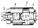
제1도는 노리쇠 돌기를 포함하는 노리쇠와 본 발명의 리시버(receiver)의 일부를 보인 소총의 일부 절개측면도.1 is a partial cutaway side view of a rifle showing a clasp including a clasp protrusion and a portion of a receiver of the present invention.
제2도는 리시버를 보인 소총의 평면도.2 is a plan view of the rifle showing the receiver.
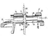
제3도는 단면으로 보인 브로우치(broach)로 제조중에 있는 본 발명 리시버의 평면도.3 is a plan view of the receiver of the present invention in manufacture with a broach shown in cross section.
제4도는 제3도의 4-4선 단면도.4 is a cross-sectional view taken along line 4-4 of FIG.
* 도면의 주요부분에 대한 부호의 설명* Explanation of symbols for main parts of the drawings
12 : 리시버 14 : 노리쇠12: receiver 14: bolt
23 : 전방부 24 : 후방부23: front part 24: rear part
27,28 : 돌기 27a,28a : 돌기좌27,28 projections 27a, 28a projections
30 : 개머리개방부 35 : 브로우치.30: open head part 35: brooch.
본 발명은 노리쇠돌기가 삽입되는 돌기좌(突起座)를 갖는 소총용 리시버와 이러한 돌기좌를 갖는 리시버의 제조방법에 관한 것이다.TECHNICAL FIELD The present invention relates to a rifle receiver having a projection seat into which a projection is inserted, and a method of manufacturing a receiver having such projection seat.
종래 소총의 리시버에 있어서는 돌기좌가 간격을 두고 떨어져 있어 돌기좌를 포함하는 리시버의 제조에 많은 작업단계를 거쳐야하고 요구된 유극을 얻지 못하는 결점이 있었다.In conventional rifle receivers, the projection seats are spaced apart from each other, and thus, the manufacturing process of the receiver including the projection seats requires a lot of work steps, and there is a drawback of failing to obtain the required clearance.
본 발명에 있어서는 새로운 리시버와 그 제조방법을 제공함으로서 종래의 결점을 해결하는데 그 목적이 있다.In the present invention, it is an object to solve the conventional drawbacks by providing a new receiver and its manufacturing method.
본 발명의 리서버를 전방으로 개머리개방부를 가지며, 후방으로 하나 또는 그 이상의 노리쇠돌기가 삽입되는 돌기좌가 형성되는데 이들은 간단한 브로우치 가공으로 간단히 형성된다. 브로우치는 돌기좌를 연삭하기 위하여 개머리개방부로 삽입된다. 형성된 돌기좌가 총신의 총구에 대하여 수직인 평면에 놓이는 것이 특징이다.The reserver of the present invention has a protruding opening to the front, and a protruding seat is formed into which one or more staple protrusions are inserted to the rear, which are simply formed by simple broaching. The broach is inserted into the opening to grind the protruding seat. The protruding seat formed is in a plane perpendicular to the barrel of the barrel.
또한 리시버원판이 형성된 돌기좌에 인접한 부분에서 금속재료의 양을 조절하여 주조될 수 있어 돌기좌가 브로우치가공 공구의 1회 왕복으로 간단히 구성될 수 있다.In addition, the receiver disc may be cast by controlling the amount of metal material at a portion adjacent to the protrusion which is formed, so that the protrusion may be simply configured by one round trip of the broaching tool.
본 발명의 첨부도면에 의거하여 보다 상세히 설명하면 다음과 같다.When described in more detail based on the accompanying drawings of the present invention.
제1도 및 제2도에서, 소총(10)은 총신(11), 리시버(12), 개머리노리쇠조립체(13), 노리쇠(14), 노리쇠손잡이(16), 노리쇠 헤드슬리이브(17)와 격침(19)을 포함한다. 또한 개머리판(21)과 삽입고정부(22)가 도시되어 있다. 리시버(12)는 전방부(23), 후방부(24)와 속이 빈 개머리 부분(26)을 포함한다. 노리쇠(14)에는 상부노리쇠돌기(27)와 하부노리쇠돌기(28)가 돔설되어 있다. 리시버 후방부(24)에는 상부돌기좌(27a)와 하부 돌기좌(28a)가 형성되어 있다.In FIGS. 1 and 2, the rifle 10 includes a barrel 11, a receiver 12, a butt assembly 13, a bolt 14, a bolt handle 16, a bolt head sleeve 17. And sinking 19. Also shown are the butt plate 21 and the insertion fixing part 22. The receiver 12 includes a
노리쇠돌기(27)(28)는 노리쇠가 폐쇄위치에 있을 때(제1도) 리시버돌기좌(27a)(28a)에 각각 삽입된다.The collar projections 27 and 28 are respectively inserted into the receiver projection seats 27a and 28a when the collar is in the closed position (FIG. 1).
제3도 및 제4도에서, 리시버돌기좌(27a)(28a)의 제조방법이 도시되어 있으며, 여기에서 브로우치(35)가 개머리개방부(30)에 삽입되어 있음이 도시되어 있다. 처음 리시버원판은 정밀주조, 단조 또는 다른 방법으로 성형된다. 그리고 리시버원판의 각 부분이 연삭, 연마 또는 공지의 방법으로 가공된다.3 and 4, a method of manufacturing the receiver protruding seats 27a and 28a is shown, where the broach 35 is inserted into the butt opening 30. As shown in FIG. Initially, the receiver disc is molded by precision casting, forging or other means. And each part of a receiver disc is processed by grinding, grinding | polishing, or a well-known method.
이러한 제조공정의 일부로서, 후방부(24)의 전면(31)(32)은 요구된 돌기좌(27a)(28a)를 제공토록 연삭가공에 의하여 부분적으로 제거된다. 본 발명에 있어서는, 리시버후방부(24)의 전면(31)(32)에 금속재료를 포함하고 있으므로 연삭에 의하여 전면(31)(32)의 금속재료가 제거되고 허용유극을 갖는 적당한 크기의 돌기좌(27a)(28a)가 제공된다. 또한 본 발명의 제조방법은 전면(31)(32)의 금속량이 브로우치공구의 1회왕복만으로 연삭될 수 있는 양을 초과하지 않도록 되어있다. 전면(31)(32)의 금속량을 조절함으로서 돌기좌(37a)(28a)가 브로우치공구의 1회왕복으로 형성될 수 있다.As part of this manufacturing process, the front surfaces 31 and 32 of the rear part 24 are partially removed by grinding to provide the required projection seats 27a and 28a. In the present invention, since the front surfaces 31 and 32 of the receiver rear part 24 contain metal materials, the projections of a suitable size having the metal material of the front surfaces 31 and 32 removed by grinding and having an allowable clearance therebetween. Seats 27a and 28a are provided. In addition, the manufacturing method of the present invention is such that the amount of metal on the front surfaces 31 and 32 does not exceed the amount that can be ground with only one round trip of the broach tool. By adjusting the amount of metal on the front surfaces 31 and 32, the protruding seats 37a and 28a can be formed in one round trip of the broach tool.
제4도에서, 브로우치(35)는 이 브로우치(35)가 하향될 때에(제4도의 화살표 참조), 전면(31)(32)으로부터 금속을 연삭하는 톱니(36)를 갖는다. 브로우치(35)는 돌기좌(27a)(28a)를 형성하도록 하는 전면(31)(32)의 연삭이 1회왕복으로 충분히 수행될 수 있는 선택된 크기, 길이 및 각도의 톱니를 갖는다. 이 브로우치(35)는 총신의 축 또는 이에 평행한 선(제4도의 중심선 C/L참조)에 대하여 수직으로 놓이게 하는 것이 좋다. 브로우치 연삭행정중의 이러한 브로우치(35)의 방향으로 돌기좌(27a)(28a)는 총신단부로부터 동일거리의 동일 평면내에 형성될 것이다.In FIG. 4, the brooch 35 has
Claims (4)
Applications Claiming Priority (2)
| Application Number | Priority Date | Filing Date | Title |
|---|---|---|---|
| US49050483A | 1983-05-02 | 1983-05-02 | |
| US490504 | 1983-05-02 |
Publications (2)
| Publication Number | Publication Date |
|---|---|
| KR850001999A KR850001999A (en) | 1985-04-10 |
| KR860000045B1 true KR860000045B1 (en) | 1986-01-30 |
Family
ID=23948343
Family Applications (1)
| Application Number | Title | Priority Date | Filing Date |
|---|---|---|---|
| KR1019830003839A KR860000045B1 (en) | 1983-05-02 | 1983-08-17 | Receiver for bolt action firearm & method of manufacture |
Country Status (10)
| Country | Link |
|---|---|
| EP (1) | EP0130253B1 (en) |
| JP (1) | JPS59202400A (en) |
| KR (1) | KR860000045B1 (en) |
| AR (1) | AR231353A1 (en) |
| AU (1) | AU562369B2 (en) |
| BR (1) | BR8304628A (en) |
| DE (1) | DE3378593D1 (en) |
| ES (2) | ES525211A0 (en) |
| MX (1) | MX156730A (en) |
| PT (1) | PT77236B (en) |
Families Citing this family (1)
| Publication number | Priority date | Publication date | Assignee | Title |
|---|---|---|---|---|
| US4719714A (en) * | 1986-06-19 | 1988-01-19 | Louis Palmisano | Locking lug insert for a firearm receiver |
Family Cites Families (4)
| Publication number | Priority date | Publication date | Assignee | Title |
|---|---|---|---|---|
| US1924692A (en) * | 1931-05-28 | 1933-08-29 | Remington Arms Co Inc | Firearm |
| FR794614A (en) * | 1935-09-06 | 1936-02-21 | Manufacturing process for breech boxes, movable breeches or similar parts of rifles | |
| US2606382A (en) * | 1948-11-29 | 1952-08-12 | Wilbur A Schaich | Two-piece firearm bolt |
| AT281637B (en) * | 1968-06-04 | 1970-05-25 | Furtschegger W | Lock of an army rifle |
-
1983
- 1983-07-28 AU AU17387/83A patent/AU562369B2/en not_active Ceased
- 1983-08-17 KR KR1019830003839A patent/KR860000045B1/en not_active IP Right Cessation
- 1983-08-23 PT PT77236A patent/PT77236B/en not_active IP Right Cessation
- 1983-08-26 BR BR8304628A patent/BR8304628A/en not_active IP Right Cessation
- 1983-08-29 ES ES525211A patent/ES525211A0/en active Granted
- 1983-08-30 DE DE8383304997T patent/DE3378593D1/en not_active Expired
- 1983-08-30 EP EP83304997A patent/EP0130253B1/en not_active Expired
- 1983-08-30 MX MX198556A patent/MX156730A/en unknown
- 1983-08-30 JP JP58158940A patent/JPS59202400A/en active Granted
- 1983-08-31 AR AR294068A patent/AR231353A1/en active
-
1984
- 1984-01-27 ES ES1984277149U patent/ES277149Y/en not_active Expired
Also Published As
| Publication number | Publication date |
|---|---|
| ES277149Y (en) | 1986-10-01 |
| MX156730A (en) | 1988-09-28 |
| EP0130253B1 (en) | 1988-11-30 |
| JPS59202400A (en) | 1984-11-16 |
| JPH0366600B2 (en) | 1991-10-17 |
| DE3378593D1 (en) | 1989-01-05 |
| BR8304628A (en) | 1985-02-20 |
| AU1738783A (en) | 1984-11-08 |
| PT77236B (en) | 1986-02-17 |
| AU562369B2 (en) | 1987-06-11 |
| ES277149U (en) | 1986-02-01 |
| ES8406256A1 (en) | 1984-08-01 |
| PT77236A (en) | 1983-09-01 |
| AR231353A1 (en) | 1984-10-31 |
| ES525211A0 (en) | 1984-08-01 |
| EP0130253A3 (en) | 1985-10-09 |
| EP0130253A2 (en) | 1985-01-09 |
| KR850001999A (en) | 1985-04-10 |
Similar Documents
| Publication | Publication Date | Title |
|---|---|---|
| US2635327A (en) | Hack saw | |
| US4143920A (en) | Mineral cutting pick insert shape | |
| FR2592608A1 (en) | KNIFE BLADE AND MANUFACTURING METHOD THEREOF. | |
| US2589357A (en) | Diamond type tooth for rotary stone cutting saws | |
| EP0122334A2 (en) | Milling cutter and method of assembling therefor | |
| GB2196567A (en) | Stud welding tool | |
| KR860000045B1 (en) | Receiver for bolt action firearm & method of manufacture | |
| US4593488A (en) | Receiver for bolt action firearm and method of manufacture | |
| US4051954A (en) | Coupler butt end replacement method and part | |
| US3590893A (en) | Method of fastening blades to sawing tools | |
| AU641724B2 (en) | A metal cutting tool | |
| KR0124794B1 (en) | Cutting tool | |
| GB1562065A (en) | Multiple-operation tool carrier assembly | |
| US2187640A (en) | Stock fastening means | |
| US2104604A (en) | Cutter clamping mechanism | |
| US2783050A (en) | Locating stud | |
| US1890997A (en) | Forged dipper tooth | |
| US4016634A (en) | Indexable insert type cutting toolholders | |
| US3528154A (en) | Individual tooth broach | |
| US1761755A (en) | Process of making metal-working tools | |
| US3707788A (en) | Locking means for cap-type tooth | |
| US4798075A (en) | Method and apparatus for making a bowed external spring retaining ring of the E-shaped type | |
| JP2529997Y2 (en) | Replaceable blade type only | |
| EP0055998B2 (en) | Tool element | |
| EP0366047B1 (en) | Grooving or threading tool |
Legal Events
| Date | Code | Title | Description |
|---|---|---|---|
| A201 | Request for examination | ||
| G160 | Decision to publish patent application | ||
| E701 | Decision to grant or registration of patent right | ||
| GRNT | Written decision to grant | ||
| FPAY | Annual fee payment |
Payment date: 19931116 Year of fee payment: 9 |
|
| LAPS | Lapse due to unpaid annual fee |