EP0130253B1 - Receiver for bolt action firearm and method of manufacture - Google Patents
Receiver for bolt action firearm and method of manufacture Download PDFInfo
- Publication number
- EP0130253B1 EP0130253B1 EP83304997A EP83304997A EP0130253B1 EP 0130253 B1 EP0130253 B1 EP 0130253B1 EP 83304997 A EP83304997 A EP 83304997A EP 83304997 A EP83304997 A EP 83304997A EP 0130253 B1 EP0130253 B1 EP 0130253B1
- Authority
- EP
- European Patent Office
- Prior art keywords
- receiver
- bolt
- rearward
- broach
- rearward portion
- Prior art date
- Legal status (The legal status is an assumption and is not a legal conclusion. Google has not performed a legal analysis and makes no representation as to the accuracy of the status listed.)
- Expired
Links
Images
Classifications
-
- F—MECHANICAL ENGINEERING; LIGHTING; HEATING; WEAPONS; BLASTING
- F41—WEAPONS
- F41A—FUNCTIONAL FEATURES OR DETAILS COMMON TO BOTH SMALLARMS AND ORDNANCE, e.g. CANNONS; MOUNTINGS FOR SMALLARMS OR ORDNANCE
- F41A3/00—Breech mechanisms, e.g. locks
- F41A3/64—Mounting of breech-blocks; Accessories for breech-blocks or breech-block mountings
- F41A3/66—Breech housings or frames; Receivers
Definitions
- This invention relates to receivers used in rifles which receivers have seating surfaces against which bolt lugs are positioned and to the method of manufacture of the receiver with such seating surfaces wherein the preamble of claims 1 and 3 is based on US-A-1924692.
- the present invention overcomes weaknesses of the prior art by providing an improved receiver and method of manufacture.
- a receiver for a bolt action firearm having a barrel, a bolt with lugs a stock, a receiver housing having a forward portion adapted to engage the barrel, a rearward portion adapted to engage the stock and hollow breech portion between said forward and rearward portions characterised in that there is provided; two seat surfaces on the rearward receiver portions for mating with spaced lugs on the bolt, said seat surfaces being formed by a single stroke of a broach cutting means.
- a method of manufacture of a receiver for a bolt action firearm comprising a rearward position with a breech opening adjacent thereto characterised in that the method includes the steps of:-
- the invention concerns the formation of a receiver having forward, breech opening and rearward portions with two spaced bolt lugs seats positioned on the rearward portion so that they can be readily formed by the simple broaching operation.
- the broach is passed through the breech opening to machine the lug seats.
- the lug seats may afterforming g lie in a plane perpendicular to the bore of the rifle barrel.
- the receiver blank can be cast with a controlled amount of metal material in the areas adjacent the seats to be formed such that the seats can be formed in a single stroke of a broaching tool.
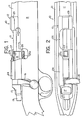
- rifle 10 includes barrel 11, receiver 12, breech bolt assembly 13, bolt 14, bolt handle 16, bolt head sleeve 17 and cocking piece 19. Also shown are stock 21 and tang 22.
- Receiver 12 includes forward portion 23, rearward portion 24 and a hollow breech portion 26.
- Bolt 14 carries upper bolt lug 27 and lower bolt lug 28.
- Forward receiver portion 24 has upper lug seat 27a and lower lug seat 28a.
- Bolt lugs 27 and 28 engage receiver lug seats 27a and 28a when the bolt is in its closed position (Fig. 1).
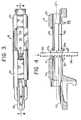
- Figs. 3 and 4 the method of manufacture of receiver lug seats 27a and 28a is shown in which a broach 35 is positioned in breech opening 30.
- the receiver blank is formed by investment casting, forging or other method. Portions of the receiver blank are then finished by machining, grinding or otherwise as known in the art.
- the forward areas 31, 32 of the rearward portion 24 are partially removed by machining to provide the desired location of surfaces 27a and 28a.
- the receiver blank includes metal material in the forward areas 31, 32 of the rearward receiver portion 24 so that metal removed from area 31, 32 by machining provides surface seats 27a, 28a of proper area and location within acceptable tolerances.
- the method of manufacture provides that the volume of metal material in areas 31,32 preferably does not exceed that which can be machined by one stroke of a broach tool. By controlling the amount of metal in areas 31, 32 seats 27a, 28a can be formed in one broach stroke.
- broach tool 35 has broach teeth 36 which machine metal from the forward areas 31, 32 as broach 35 is moved downwardly (see arrow in Fig. 4).
- Broach 35 carries sufficient teeth of selected size, length and angle such that the machining of forward areas 31, 32 to form seat surfaces 27a and 28a is accomplished in one downward stroke.
- Broach 35 is preferably positioned to move perpendicularly to the axis of the barrel or a line parallel thereto (see centre line C/L of Fig. 4). With broach 35 so oriented during its machining stroke, seat surfaces 27a and 28a will be in the same plane and each seat surface equidistant from the end of the barrel 11.
Landscapes
- Engineering & Computer Science (AREA)
- General Engineering & Computer Science (AREA)
- Milling, Broaching, Filing, Reaming, And Others (AREA)
- Aiming, Guidance, Guns With A Light Source, Armor, Camouflage, And Targets (AREA)
- Dowels (AREA)
- Cutting Tools, Boring Holders, And Turrets (AREA)
- Forging (AREA)
- Confectionery (AREA)
Description
- This invention relates to receivers used in rifles which receivers have seating surfaces against which bolt lugs are positioned and to the method of manufacture of the receiver with such seating surfaces wherein the preamble of claims 1 and 3 is based on US-A-1924692.
- Prior rifle receivers have had spaced apart lug seating surfaces which were so positioned that manufacture of the receiver including the lug seats required numerous operational steps and often meeting required tolerances was difficult.
- The present invention overcomes weaknesses of the prior art by providing an improved receiver and method of manufacture.
- According to the present invention there is provided a receiver for a bolt action firearm having a barrel, a bolt with lugs a stock, a receiver housing having a forward portion adapted to engage the barrel, a rearward portion adapted to engage the stock and hollow breech portion between said forward and rearward portions characterised in that there is provided; two seat surfaces on the rearward receiver portions for mating with spaced lugs on the bolt, said seat surfaces being formed by a single stroke of a broach cutting means.
- According to a further aspect of the present invention there is provided a method of manufacture of a receiver for a bolt action firearm the receiver comprising a rearward position with a breech opening adjacent thereto characterised in that the method includes the steps of:-
- a) forming a metal receiver blank having the rearward portion and the breech opening adjacent thereto;
- b) controlling the amount of metal in said rearward portion to an amount which does not exceed that which can be machined by a single stroke of a broaching tool, and
- c) passing a broach means through the breech opening to remove metal from the rearward portion to form at least two spaced apart bolt lug seat surfaces thereon. at least one bolt lug seat thereon.
- As will be apparent from the foregoing, the invention concerns the formation of a receiver having forward, breech opening and rearward portions with two spaced bolt lugs seats positioned on the rearward portion so that they can be readily formed by the simple broaching operation. The broach is passed through the breech opening to machine the lug seats.
- It is a feature that the lug seats may afterforming g lie in a plane perpendicular to the bore of the rifle barrel.
- It is also a feature that the receiver blank can be cast with a controlled amount of metal material in the areas adjacent the seats to be formed such that the seats can be formed in a single stroke of a broaching tool.
- An embodiment of the present invention will now be described, by way of example, with reference to the accompanying drawings in which:-
- Fig. 1 is a side elevtional view of a rifle, partially broken away, to show portions of the bolt including the bolt lugs and the receiver of this invention;
- Fig. 2 is a plan view of the rifle showing the receiver;
- Fig. 3 is a plan view of the receiver of the invention during manufacture with the broach shown in section; and
- Fig. 4 is the section along line 4-4 of Fig. 3.
- Referring to Figs. 1 and 2, rifle 10 includes barrel 11,
receiver 12,breech bolt assembly 13,bolt 14,bolt handle 16,bolt head sleeve 17 and cocking piece 19. Also shown arestock 21 andtang 22. -
Receiver 12 includesforward portion 23,rearward portion 24 and ahollow breech portion 26.Bolt 14 carriesupper bolt lug 27 andlower bolt lug 28.Forward receiver portion 24 hasupper lug seat 27a and lower lug seat 28a. Bolt lugs 27 and 28 engagereceiver lug seats 27a and 28a when the bolt is in its closed position (Fig. 1). - Turning to Figs. 3 and 4, the method of manufacture of
receiver lug seats 27a and 28a is shown in which abroach 35 is positioned in breech opening 30. Initially, the receiver blank is formed by investment casting, forging or other method. Portions of the receiver blank are then finished by machining, grinding or otherwise as known in the art. As part of this manufacturing process, theforward areas rearward portion 24 are partially removed by machining to provide the desired location ofsurfaces 27a and 28a. In the practice of this invention, the receiver blank includes metal material in theforward areas rearward receiver portion 24 so that metal removed fromarea surface seats 27a, 28a of proper area and location within acceptable tolerances. Further the method of manufacture provides that the volume of metal material inareas areas seats 27a, 28a can be formed in one broach stroke. - Referring to Fig. 4,
broach tool 35 hasbroach teeth 36 which machine metal from theforward areas broach 35 is moved downwardly (see arrow in Fig. 4).Broach 35 carries sufficient teeth of selected size, length and angle such that the machining offorward areas seat surfaces 27a and 28a is accomplished in one downward stroke.Broach 35 is preferably positioned to move perpendicularly to the axis of the barrel or a line parallel thereto (see centre line C/L of Fig. 4). Withbroach 35 so oriented during its machining stroke,seat surfaces 27a and 28a will be in the same plane and each seat surface equidistant from the end of the barrel 11.
Claims (4)
Applications Claiming Priority (2)
| Application Number | Priority Date | Filing Date | Title |
|---|---|---|---|
| US49050483A | 1983-05-02 | 1983-05-02 | |
| US490504 | 1983-05-02 |
Publications (3)
| Publication Number | Publication Date |
|---|---|
| EP0130253A2 EP0130253A2 (en) | 1985-01-09 |
| EP0130253A3 EP0130253A3 (en) | 1985-10-09 |
| EP0130253B1 true EP0130253B1 (en) | 1988-11-30 |
Family
ID=23948343
Family Applications (1)
| Application Number | Title | Priority Date | Filing Date |
|---|---|---|---|
| EP83304997A Expired EP0130253B1 (en) | 1983-05-02 | 1983-08-30 | Receiver for bolt action firearm and method of manufacture |
Country Status (10)
| Country | Link |
|---|---|
| EP (1) | EP0130253B1 (en) |
| JP (1) | JPS59202400A (en) |
| KR (1) | KR860000045B1 (en) |
| AR (1) | AR231353A1 (en) |
| AU (1) | AU562369B2 (en) |
| BR (1) | BR8304628A (en) |
| DE (1) | DE3378593D1 (en) |
| ES (2) | ES525211A0 (en) |
| MX (1) | MX156730A (en) |
| PT (1) | PT77236B (en) |
Families Citing this family (1)
| Publication number | Priority date | Publication date | Assignee | Title |
|---|---|---|---|---|
| US4719714A (en) * | 1986-06-19 | 1988-01-19 | Louis Palmisano | Locking lug insert for a firearm receiver |
Family Cites Families (4)
| Publication number | Priority date | Publication date | Assignee | Title |
|---|---|---|---|---|
| US1924692A (en) * | 1931-05-28 | 1933-08-29 | Remington Arms Co Inc | Firearm |
| FR794614A (en) * | 1935-09-06 | 1936-02-21 | Manufacturing process for breech boxes, movable breeches or similar parts of rifles | |
| US2606382A (en) * | 1948-11-29 | 1952-08-12 | Wilbur A Schaich | Two-piece firearm bolt |
| AT281637B (en) * | 1968-06-04 | 1970-05-25 | Furtschegger W | Lock of an army rifle |
-
1983
- 1983-07-28 AU AU17387/83A patent/AU562369B2/en not_active Ceased
- 1983-08-17 KR KR1019830003839A patent/KR860000045B1/en not_active IP Right Cessation
- 1983-08-23 PT PT77236A patent/PT77236B/en not_active IP Right Cessation
- 1983-08-26 BR BR8304628A patent/BR8304628A/en not_active IP Right Cessation
- 1983-08-29 ES ES525211A patent/ES525211A0/en active Granted
- 1983-08-30 DE DE8383304997T patent/DE3378593D1/en not_active Expired
- 1983-08-30 EP EP83304997A patent/EP0130253B1/en not_active Expired
- 1983-08-30 MX MX198556A patent/MX156730A/en unknown
- 1983-08-30 JP JP58158940A patent/JPS59202400A/en active Granted
- 1983-08-31 AR AR294068A patent/AR231353A1/en active
-
1984
- 1984-01-27 ES ES1984277149U patent/ES277149Y/en not_active Expired
Also Published As
| Publication number | Publication date |
|---|---|
| ES277149Y (en) | 1986-10-01 |
| MX156730A (en) | 1988-09-28 |
| JPS59202400A (en) | 1984-11-16 |
| JPH0366600B2 (en) | 1991-10-17 |
| DE3378593D1 (en) | 1989-01-05 |
| BR8304628A (en) | 1985-02-20 |
| AU1738783A (en) | 1984-11-08 |
| PT77236B (en) | 1986-02-17 |
| AU562369B2 (en) | 1987-06-11 |
| ES277149U (en) | 1986-02-01 |
| ES8406256A1 (en) | 1984-08-01 |
| PT77236A (en) | 1983-09-01 |
| AR231353A1 (en) | 1984-10-31 |
| ES525211A0 (en) | 1984-08-01 |
| EP0130253A3 (en) | 1985-10-09 |
| EP0130253A2 (en) | 1985-01-09 |
| KR850001999A (en) | 1985-04-10 |
| KR860000045B1 (en) | 1986-01-30 |
Similar Documents
| Publication | Publication Date | Title |
|---|---|---|
| US4198879A (en) | Method for the manufacture of connecting rods for small reciprocating engines | |
| US4593488A (en) | Receiver for bolt action firearm and method of manufacture | |
| EP0192872A1 (en) | Saw blade and tip therefor | |
| US6632051B1 (en) | Cutting bit, cutting tool and method for machining, especially rotationally symmetrical work piece surfaces | |
| JPH06155158A (en) | Saw blade | |
| KR100568883B1 (en) | Cutting tool for producing toothed articles | |
| US20210102778A1 (en) | Pistol frame | |
| US3422706A (en) | Gun drill | |
| US3104562A (en) | Saw | |
| EP1188905B1 (en) | Seat faced engine valves and method of making the same | |
| EP0130253B1 (en) | Receiver for bolt action firearm and method of manufacture | |
| CA1215295A (en) | Cutting link for a chain cutter | |
| EP0412950B1 (en) | Broaching assembly | |
| US5738060A (en) | Poppet valve and method of making the poppet valve | |
| US20050005443A1 (en) | Method for producing a connecting rod for a reciprocating-piston engine | |
| EP0592179A1 (en) | Reconditioning engine parts | |
| US2656590A (en) | Broach | |
| US2622464A (en) | Pivoted hand tool | |
| US6119497A (en) | Method for use with a lathe for forming a journal on metal stock | |
| AU700739B2 (en) | Reforged flight bar and method of making the same | |
| RU190141U1 (en) | PULL-UP | |
| US4067400A (en) | Pneumatic hammer | |
| US2530363A (en) | Action slide for firearms | |
| US2164874A (en) | Broaching cutter for stub ball joint | |
| DE4124646A1 (en) | Inserted tooth cutter for machining I.C. engine valve seatings - has reversible insert in form of ribbed base section with brazed hardmetal strips having different profiles on two end faces |
Legal Events
| Date | Code | Title | Description |
|---|---|---|---|
| PUAI | Public reference made under article 153(3) epc to a published international application that has entered the european phase |
Free format text: ORIGINAL CODE: 0009012 |
|
| AK | Designated contracting states |
Designated state(s): BE DE FR GB IT LU NL |
|
| PUAL | Search report despatched |
Free format text: ORIGINAL CODE: 0009013 |
|
| AK | Designated contracting states |
Designated state(s): BE DE FR GB IT LU NL |
|
| 17P | Request for examination filed |
Effective date: 19860407 |
|
| 17Q | First examination report despatched |
Effective date: 19870224 |
|
| GRAA | (expected) grant |
Free format text: ORIGINAL CODE: 0009210 |
|
| AK | Designated contracting states |
Kind code of ref document: B1 Designated state(s): BE DE FR GB IT LU NL |
|
| ITF | It: translation for a ep patent filed |
Owner name: JACOBACCI & PERANI S.P.A. |
|
| REF | Corresponds to: |
Ref document number: 3378593 Country of ref document: DE Date of ref document: 19890105 |
|
| ET | Fr: translation filed | ||
| PLBE | No opposition filed within time limit |
Free format text: ORIGINAL CODE: 0009261 |
|
| STAA | Information on the status of an ep patent application or granted ep patent |
Free format text: STATUS: NO OPPOSITION FILED WITHIN TIME LIMIT |
|
| 26N | No opposition filed | ||
| PGFP | Annual fee paid to national office [announced via postgrant information from national office to epo] |
Ref country code: GB Payment date: 19920625 Year of fee payment: 10 |
|
| PGFP | Annual fee paid to national office [announced via postgrant information from national office to epo] |
Ref country code: LU Payment date: 19920710 Year of fee payment: 10 |
|
| PGFP | Annual fee paid to national office [announced via postgrant information from national office to epo] |
Ref country code: NL Payment date: 19920831 Year of fee payment: 10 |
|
| EPTA | Lu: last paid annual fee | ||
| PG25 | Lapsed in a contracting state [announced via postgrant information from national office to epo] |
Ref country code: LU Free format text: LAPSE BECAUSE OF NON-PAYMENT OF DUE FEES Effective date: 19930830 Ref country code: GB Effective date: 19930830 |
|
| ITTA | It: last paid annual fee | ||
| PG25 | Lapsed in a contracting state [announced via postgrant information from national office to epo] |
Ref country code: NL Effective date: 19940301 |
|
| NLV4 | Nl: lapsed or anulled due to non-payment of the annual fee | ||
| GBPC | Gb: european patent ceased through non-payment of renewal fee |
Effective date: 19930830 |
|
| PGFP | Annual fee paid to national office [announced via postgrant information from national office to epo] |
Ref country code: DE Payment date: 19940728 Year of fee payment: 12 |
|
| PGFP | Annual fee paid to national office [announced via postgrant information from national office to epo] |
Ref country code: BE Payment date: 19940729 Year of fee payment: 12 |
|
| PGFP | Annual fee paid to national office [announced via postgrant information from national office to epo] |
Ref country code: FR Payment date: 19940802 Year of fee payment: 12 |
|
| PG25 | Lapsed in a contracting state [announced via postgrant information from national office to epo] |
Ref country code: BE Effective date: 19950831 |
|
| BERE | Be: lapsed |
Owner name: STURM RUGER & CY INC. Effective date: 19950831 |
|
| PG25 | Lapsed in a contracting state [announced via postgrant information from national office to epo] |
Ref country code: FR Effective date: 19960430 |
|
| PG25 | Lapsed in a contracting state [announced via postgrant information from national office to epo] |
Ref country code: DE Effective date: 19960501 |
|
| REG | Reference to a national code |
Ref country code: FR Ref legal event code: ST |