KR850000460B1 - Pellet work piece container boat loading apparatus - Google Patents
Pellet work piece container boat loading apparatus Download PDFInfo
- Publication number
- KR850000460B1 KR850000460B1 KR1019810002645A KR810002645A KR850000460B1 KR 850000460 B1 KR850000460 B1 KR 850000460B1 KR 1019810002645 A KR1019810002645 A KR 1019810002645A KR 810002645 A KR810002645 A KR 810002645A KR 850000460 B1 KR850000460 B1 KR 850000460B1
- Authority
- KR
- South Korea
- Prior art keywords
- pellet
- boat
- container
- workpiece
- limit switch
- Prior art date
Links
Images


Classifications
-
- F—MECHANICAL ENGINEERING; LIGHTING; HEATING; WEAPONS; BLASTING
- F27—FURNACES; KILNS; OVENS; RETORTS
- F27D—DETAILS OR ACCESSORIES OF FURNACES, KILNS, OVENS, OR RETORTS, IN SO FAR AS THEY ARE OF KINDS OCCURRING IN MORE THAN ONE KIND OF FURNACE
- F27D3/00—Charging; Discharging; Manipulation of charge
- F27D3/0024—Charging; Discharging; Manipulation of charge of metallic workpieces
-
- G—PHYSICS
- G21—NUCLEAR PHYSICS; NUCLEAR ENGINEERING
- G21C—NUCLEAR REACTORS
- G21C21/00—Apparatus or processes specially adapted to the manufacture of reactors or parts thereof
-
- F—MECHANICAL ENGINEERING; LIGHTING; HEATING; WEAPONS; BLASTING
- F27—FURNACES; KILNS; OVENS; RETORTS
- F27B—FURNACES, KILNS, OVENS, OR RETORTS IN GENERAL; OPEN SINTERING OR LIKE APPARATUS
- F27B21/00—Open or uncovered sintering apparatus; Other heat-treatment apparatus of like construction
- F27B21/04—Sintering pots or sintering pans
-
- F—MECHANICAL ENGINEERING; LIGHTING; HEATING; WEAPONS; BLASTING
- F27—FURNACES; KILNS; OVENS; RETORTS
- F27D—DETAILS OR ACCESSORIES OF FURNACES, KILNS, OVENS, OR RETORTS, IN SO FAR AS THEY ARE OF KINDS OCCURRING IN MORE THAN ONE KIND OF FURNACE
- F27D3/00—Charging; Discharging; Manipulation of charge
- F27D2003/0001—Positioning the charge
- F27D2003/0004—Positioning the charge involving devices for measuring the article, the stack of articles or the height of the furnace passage or for adjusting the height of the passage to the charge or for putting the articles in the same position
-
- F—MECHANICAL ENGINEERING; LIGHTING; HEATING; WEAPONS; BLASTING
- F27—FURNACES; KILNS; OVENS; RETORTS
- F27D—DETAILS OR ACCESSORIES OF FURNACES, KILNS, OVENS, OR RETORTS, IN SO FAR AS THEY ARE OF KINDS OCCURRING IN MORE THAN ONE KIND OF FURNACE
- F27D3/00—Charging; Discharging; Manipulation of charge
- F27D2003/0001—Positioning the charge
- F27D2003/0018—Positioning the charge comprising means to introduce or extract the charge in series of separate containers or zones
- F27D2003/0019—Positioning the charge comprising means to introduce or extract the charge in series of separate containers or zones simultaneously
-
- F—MECHANICAL ENGINEERING; LIGHTING; HEATING; WEAPONS; BLASTING
- F27—FURNACES; KILNS; OVENS; RETORTS
- F27D—DETAILS OR ACCESSORIES OF FURNACES, KILNS, OVENS, OR RETORTS, IN SO FAR AS THEY ARE OF KINDS OCCURRING IN MORE THAN ONE KIND OF FURNACE
- F27D3/00—Charging; Discharging; Manipulation of charge
- F27D2003/0034—Means for moving, conveying, transporting the charge in the furnace or in the charging facilities
- F27D2003/0068—Means for moving, conveying, transporting the charge in the furnace or in the charging facilities comprising clamps or tongs
-
- F—MECHANICAL ENGINEERING; LIGHTING; HEATING; WEAPONS; BLASTING
- F27—FURNACES; KILNS; OVENS; RETORTS
- F27D—DETAILS OR ACCESSORIES OF FURNACES, KILNS, OVENS, OR RETORTS, IN SO FAR AS THEY ARE OF KINDS OCCURRING IN MORE THAN ONE KIND OF FURNACE
- F27D5/00—Supports, screens, or the like for the charge within the furnace
- F27D5/0068—Containers
-
- F—MECHANICAL ENGINEERING; LIGHTING; HEATING; WEAPONS; BLASTING
- F27—FURNACES; KILNS; OVENS; RETORTS
- F27M—INDEXING SCHEME RELATING TO ASPECTS OF THE CHARGES OR FURNACES, KILNS, OVENS OR RETORTS
- F27M2001/00—Composition, conformation or state of the charge
- F27M2001/18—Composition, conformation or state of the charge in the form of pellets
-
- Y—GENERAL TAGGING OF NEW TECHNOLOGICAL DEVELOPMENTS; GENERAL TAGGING OF CROSS-SECTIONAL TECHNOLOGIES SPANNING OVER SEVERAL SECTIONS OF THE IPC; TECHNICAL SUBJECTS COVERED BY FORMER USPC CROSS-REFERENCE ART COLLECTIONS [XRACs] AND DIGESTS
- Y02—TECHNOLOGIES OR APPLICATIONS FOR MITIGATION OR ADAPTATION AGAINST CLIMATE CHANGE
- Y02E—REDUCTION OF GREENHOUSE GAS [GHG] EMISSIONS, RELATED TO ENERGY GENERATION, TRANSMISSION OR DISTRIBUTION
- Y02E30/00—Energy generation of nuclear origin
- Y02E30/30—Nuclear fission reactors
Abstract
Description
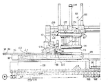
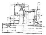
제1a도 및 제1b도는 본 펠리트 가공물 콘테이나 적재장치의 측면도.1A and 1B are side views of the present pellet workpiece or loading device.
제2a도 및 제2b도는 제1도에 도시된 장치의 평면도.2a and 2b show a plan view of the apparatus shown in FIG.
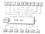
제3도는 펠리트 가공물 적재장치와 차례로 연결되도록 제공된 입력제한 스위치 및 출력작동 장치에 연결되는 본 발명의 프로그램 제어기의 개략도.3 is a schematic diagram of a program controller of the present invention connected to an input limit switch and an output actuating device provided in turn to be connected with a pellet workpiece loading device.
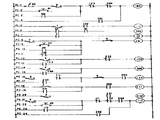
제4a도, 제4b도 및 제4c도는 제3도의 프로그램 제어기용연속 작동제어 프로그램.4A, 4B and 4C are the continuous operation control program for the program controller of FIG.
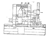
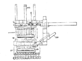
제5도는 가공물 열 압송기 및 관련장치의 평면도.5 is a plan view of the workpiece heat presser and related devices.
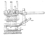
제6도는 제5도에 도시된 장치의 측면도.6 is a side view of the apparatus shown in FIG.
제7도는 유지트레이상에서 가공물이 소정의 열간격으로 진행하는 것을 도시하는 제6도 장치의 단면도.FIG. 7 is a cross-sectional view of the apparatus of FIG. 6 showing that the workpiece advances at a predetermined thermal interval above the holding tray.
제8도는 콘테이나 보우트로 하강된 트랜스퍼 헤드의 단면도.8 is a cross-sectional view of the transfer head lowered with a container or bow.
제9도는 펠리트 가공물이 적재되지 않고 제거되는 뒤틀린 빈 보우트의 단면도.9 is a cross-sectional view of a twisted empty boat in which the pellet workpiece is removed without loading.
핵 연료 제조방법의 작업 단계는 소결로에서의 펠리트 가공물의 고온 연소에 대한 준비로서 펠리트 압착기로 부터 형성된 그리인 펠리트 가공물을 소결 콘테이나 보우트속으로 적재하는 것이다. 이런 작업은 펠리트 가공물에 주의깊은 취급을 요하는데 그 이유는 이 때에 펠리트가 부서지기 쉬우며, 손상을 받기 쉽기 때문이다.The working step of the nuclear fuel production method is to load the green pellets formed from the pellet press into the sinter container or boat in preparation for the high temperature combustion of the pellets in the sintering furnace. This operation requires careful handling of the pellet workpiece because the pellets are brittle and susceptible at this time.
슈우트를 통해 펠리트 압착기로 부터 중방출된 펠리트 가공물을 소결 보우트내로 적재하며 만재된 소결보우트를 수동으로 변위시키는 것이 종전 기술에 공지되어 있다. 이런 방법은 펠리트끼리는 충돌하게 하는 단점을 가져서 펠리트 손상에 대한 상당한 잠재력을 가지고 있다. 부가적으로, 각 소결 콘테이나 보우트에서 펠리트의 임의의 방향은 적재 밀도를 줄이며 그로인해 고온 소결생산 능력을 줄인다.It is known in the art to manually load a pellet workpiece from the pellet presser through the chute into the sintering boat and manually displace the loaded sintering boat. This method has the disadvantage of causing the pellets to collide with each other and has considerable potential for pellet damage. In addition, the arbitrary orientation of the pellets in each sintered container or boat reduces the loading density and thereby the high temperature sintering production capacity.
덧붙여서, 기계화된 보우트 적재기는 한번에 단일열의 펠리트 가공물을 집어서 그 열을 소결콘테이나 보우트 내로 이송하는 기계적인 브레이드 또는조우를 가진 파지 및 위치설정장치를 구사하는 것이 이전 기술에 공지되어 있다. 이런 기계화된 보우트 적재기는 빈번한 주의를 요하며 생산성이 제한되는 데, 그 이유는 단일 열이송개념이 이런 기계화된 보우트 적재기의 작동을 유지하기 위해노동력을 요구하며 시간을 소비하기 때문이다. 또한, 보우트는 소결로내에서 펠리트를 소결하기 위하여 반복사용되며 고온에 노출되어 뒤틀림당 할 수도 있다. 그러나, 이와 같이 뒤틀림 당한 보우트는 펠리트를 수용하기 위한 그들의 내부공간을 변경시킬 뿐만 아니라 소결로내에 봉쇄를 야기하여 각 보우트내의 펠리트뿐만 아니라 소결로내의 모든 펠리트에 대하여 손상을 일으킨다.In addition, it is known in the prior art to use a mechanical braid or jaw with a mechanical braid or jaw that picks up a single row of pellet workpieces at one time and transfers the rows into a sintered container or boat. These mechanized boat loaders require frequent attention and productivity is limited because a single heat transfer concept requires labor and time to maintain the operation of these mechanized boat loaders. In addition, the bow is repeatedly used to sinter the pellets in the sintering furnace and may be warped due to exposure to high temperatures. However, these twisted boats not only change their internal space for accommodating the pellets, but also cause blockage in the sintering furnace, causing damage not only to the pellets in each boat but also to all the pellets in the sintering furnace.
적재 또는 소결작업을 하는 동안 비교적 민감한 펠리트를 손상시킴이 없이 다량의 그리인 펠리트를 소결보우트내로 적재할 수 있는 그리인 핵연료 펠리트 적재장치를 마련하는 것이 본 발명의 주요한 목적이다.It is a primary object of the present invention to provide a green fuel pellet loading device capable of loading a large amount of green pellets into a sinter boat without damaging relatively sensitive pellets during loading or sintering operations.
이러한 목적에 있어서, 본 발명은 입력 공급에서 가공물을 수용하고 콘테이나 속으로 이들 가공물을 적재시키기 위한 장치에 있으며, 콘테이나가 적재하기에 만족스러운가를 설정하기 위해 예정된 점검을 하기 위한 수단, 각 열마다 선정된 수의 가공물이 있는 다수의 가공물열을 수집하기 위한 파지부재를 구비하는 수단, 콘테이나 내에 가공물의 일층을 적재하기 위해 상기 다수의 가공물열을 이동시키는 수단 및 상기 장치에서 운동이 멀어지도록 상기 콘테이나 부재를 방면하기 위하여 콘테이나 내에 선정된 다수의 가공물층에 응답하는 수단을 갖는 것을 특징으로 한다.For this purpose, the present invention is directed to an apparatus for receiving workpieces from an input supply and for loading them into a container, the means for performing a predetermined check to establish whether the container is satisfactory for loading, each row Means for having a holding member for collecting a plurality of workpiece rows each having a predetermined number of workpieces, means for moving the plurality of workpiece rows for loading one layer of workpieces in a container, and for movement away from the apparatus And means for responding to a plurality of workpiece layers selected within the container to exit the container member.
본 발명은 부수도면에서 실시예에 의하여 도시된 양호한 실시양태의 다음 설명으로 부터 보다 쉽게 명백해질 것이다.The invention will be more readily apparent from the following description of the preferred embodiments shown by way of example in the accompanying drawings.
제1a도 및 제1b도에 도시된 장치는 차우의 소결로 열처리를 위한 준비로서의 적재를 위하여 소결 콘테이나 보우트(519)를 운반하는 컨베이어 상부에 설치된 펠리트 가공물 콘테이나 보우트 적재 장치로 구성된다. 본 장치는 보우트가 채택가능하며 이런목적을 위해 만족스러운지를 보증하도록 펠리트 가공물을 적재하기 전에 보우트의 외양을 점검하기 위하여 작동한다. 빈 보우트가 채택될 수 없으면, 적재 지역에서 방면되어 통과하며 새로운 보우트가 적재 장소로 색인되어 펠리트 가공물의 적재에 대한 타당성 및 충분한 조건을 결정하기 위해 점검된다.The apparatus shown in FIGS. 1A and 1B consists of a pellet workpiece container loading device mounted on top of a conveyor carrying a sinter container or
적재장치는 이전 펠리트 압착 작업으로부터 그리인 펠리트 가공물을 연속적으로 수용하는 펠리트 가공물 축적부를 가지고 있다. 펠리트 가공물의 연속적으로 미리 설정된 길이가 각 열에 축적됨에 따라서 각열은 지지 트레이상에 축방향으로 색인되며, 이런 축적작업은 펠리트 가공물의 소정행렬 배열이 축적되어 보우트에 적재되어야 할 소정의 층과 같아 질 때까지 계속된다.The loading device has a pellet workpiece accumulator which continuously receives the drawn pellet workpiece from the previous pellet crimping operation. Each row is axially indexed on the support tray as successively preset lengths of the pellet workpiece accumulate in each row, which accumulates a predetermined layer to which the matrix arrangement of the pellet workpiece is to be stacked and loaded onto the boat. Continue until you are equal.
제1a도에서, 입력 펠리트 가공물(500)은 압송기 부재(506)과 벽 부재(507) 사이에 일렬로 배치된다. 펠리트 가공물의 전열이 압송기(506)과 벽부재(507) 사이에 축적될 때, 제한 스위치 LSO는 압송기 실린더(100)이 압송기(506)을 우측방향으로 이동시켜서 유지 트레이(502)를 따라 펠리트가공물(500)의 열을 측방향으로 움직이게 한다.In FIG. 1A, the
제2a도에 도시된 제한 스위치 LSI은 펠리트 가공물(500)의 열에 대하여 소정의 이동거리가 설정될 때 작동하며 트레이 인덱스모터(110)를 작동시켜 새로히 위치설정된 가공물(500)의 열을포함 하는 유지트레이(502)를 펠리트 가공물(500)의 인접열 사이의 간격으로 요구되는 선정된 거리만큼 우측으로 이동시킨다. 이런 펠리트 가공물 열 축적 작업과 위치 색인은 각 열에 대하여 연속적으로 반복된다. 펠리트 가공물(500)열의 소정의 행렬배열이 유지트레이(502) 상에 배치될 때, 유지 트레이(502)에 고착된 아암(513)에 의해 운반되는 캠(512)은 트랜스퍼헤드(514)하부의 적재 위치로 우측으로 유지트레이(502)를 이동시키기 위해 트레이 인덱스모터(110)을 작동시키도록 제한 스위치 LS2를 작동시키며 상기 위치에서 아암(513)에 의해 운반되는캠(512)는 수직 실린더(C102)가 트랜스퍼 헤드(514)와 지지부재(512)를 하강시키도록 제한 스위치(LS2)로 작용된다. 트랜스퍼 헤드(514)에 의해 지지되는 픽업노즐(515)는 유지트레이(502) 상의펠리트 가공물(500)의 배열과 접촉한다. 트랜스퍼헤드(514)는 진공을 제공하여 각 가공물이 트랜스퍼헤드(514)의 노즐(515)에 고착되도록 오리피스 노즐(515)이 연결된 진공 추출기(517)과 함께 작동한다. 그런다음 트랜스퍼헤드(514)는 수평실린더(C101)이 빈콘테이나 보우트(516)의 상부로 오른쪽으로 트랜스퍼 헤드(514)를 이동시키는 제한 스위치 LS5에 의해 감지되는 최상부위치까지 수직 실린더(C102)에 의해 상승된다. 콘테이나 보우트(516)은 콘베이어 로울러(518) 상의 적재위치에 위치하며 지지부재(524)와 함께 작동하는 유지 실린더(C104)에 의해 적소에 유지된다. 트랜스퍼 헤드(514)는 제한스위치(LS7)이 작동될 때, 수직 실린더(C102)에 의해 콘테이나 보우트(516) 내로 하강된다. 제한스위치(LS7)이 작동될 때, 추출기(517)를 통한 진공이 제1a도 및 제1b도에 도시된 바와 같이 콘테이나 보우트(516)과 함께 일층위치에 있는 펠리트 가공물을 방면하기 위해 추출된 후에 시간지연이 개시된다.The limit switch LSI shown in FIG. 2A is operated when a predetermined moving distance is set with respect to a row of the
트랜스퍼헤드(514)는 수직 실린더(C102)에 의해 상승되며 제1a도에 도시된 것 같이 펠리트 가공물을 장진하기 위한 최좌측의 원위치로 수평 실린더(C101)에 의해 복귀된다. 이와 같은 작동 싸이클은 보우트(516)이 소정수의 층으로 채워질때까지, 콘테이나 보우트(516) 내에 배치된 각 펠리트 가공물층에 대하여 반복된다. 펠리트 가공물의 마지막 소정의 층이 콘테이나 보우트(516) 내에 배치될 때,지지부재(512)에 의해 운반되는 아암(522)를 따라 배치된 캠(520)은 콘테이너 보우트(516)의 소정의 펠리트 가공물층을 수용했다는 것을 지지하기 위해 제한 스위치(LS11)과 더 이상 작동하지 않으며, 이 때에 보우트(516)은 콘테이나 보우트(516)을 유지하는 위치에서 유지부재(524)를 추출하는 유지 실린더(104)에 의해 방면되며 콘베이어 로울러(518)는 콘테이나 보우트(516)이 적재위치로 부터 우측으로 이동하게 한다. 적재된 보우트(516)은 적재위치로 부터 방면될 때 실린더(C106)은 유지 실린더(C104)에 의해 이제 막하강된 유지 부재(524)에 의해 결정된 적재위치로 콘베이어 로울러(518)을 따라 이동하도록 다음 빈 보우트(526)을 방면하기 위해 작동된다.The
본 보우트 적재 장치에 의해 제공되는 장점은 충격이 상당히 감소되며 펠리트 가공물이 보다 부드럽게 취급되어 펠리트 손상에 대한 가능성이 감소되는 동시에 각 보우트층내의 적재 밀도를 높이기 위하여 보다 빽빽한 배열로 배치될 수 있도록 함으로써 소정의 펠리트 가공물 적재 작업의 생산능력을 향상시킬 수 있다는 점이다.The advantages offered by this boat loading device are that the impact is significantly reduced and the pelleted workpieces are handled more smoothly, reducing the chance of pellet damage and at the same time being arranged in a more compact arrangement to increase the loading density in each boat layer. This can improve the production capacity of a given pellet workpiece loading operation.
제2a도 및 제2b도에는 제1a도 및 제1b도에 도시된 장치의 평면도가 도시되며 펠리트 가공물(500)이 적재슈우트(501)을 통하여 유지트레이(502) 상의 열을 채우는 것을 도시하고 있다. 펠리트 가공물의 각열이 채워질 때, 펠리트 가공물의 단부는 제한 스위치(LS0)를 쳐서 압송실린더(C100)으로 하여금, 펠리트 가공물의 열을 유지레이(502)를 따라 우측으로 이동색인시키도록 한다. 그런 다음, 트레이(502)는 트레이(502) 상에서의 펠리트 가공물의 연속열 사이의 소장 간격을 마련하기 위해 인덱스 모터(110)에 의해 이동 된다. 이런 작동은 전체열의 가공물이 적재되어 제한스위치(LS0)와 접촉할때마다 연속적으로 반복된다. 압송기(506)이 실린더(C100)에 의해 우측으로 이동됨에 따라서 압송기(506)의 신장부(507)은 압송기(506)이 제2a도에 도시된 위치로 역귀환되어 부가 적인 펠리트가공물(500)이 또 다른 열을 형성하여 제한스위치(LSO)와 접촉할때까지 입력공급 슈우트(501)을 떠난 또 다른 가공물들을 차단한다. 유지트레이(502)가 좌측의 홈위치에 있을 때, 제한 스위치(LS4)가 작동된다. 유지트레이(502)가 트레이(502) 상에 소정수의 펠리트가공물열을 축적하기 위하여 충분한 거리만큼 우측으로 이동할 때, 캠(510)은 제2a도와 제2b도에 도시된 것같이 인덱스 모터(110)이 유지 트레이(502)를 장진위치로 우측으로 이동하도록 제한스위치(LS2)와 작동된다. 장진위치에 도달할 때 캠(512)는 수직실린더(C102)가 트랜스퍼 헤드(514)를 하강시켜서 유지트레이(502)에 축적된 펠리트 가공물과 접촉하도록 제한 스위치(LS2)와 작동된다. 수직실린더(C102)가 트랜스퍼헤드(514)를 하강시킴에 따라서, 제한스위치(LS6)가 작동되어 오리피스 노즐(515)에 소정의 진공을 부여하기 위하여 당 기술에 공지된 바와 같이 진공 추출기(517)을 통해 기류를 흐르게 한다.2a and 2b show a plan view of the apparatus shown in FIGS. 1a and 1b and show that the
소정의 시간간격 후, 수직 실린더(C102)는 펠리트 가공물의 배열이 유지트레이(502)에서 벗어나도록 트랜스퍼헤드(514)를 들어 올리며, 수평실린더(C101)은 제한 스위치(LS5)가 최상부위치에 도달하는 지지부재(512)에 의해 작동될 때 작동되며 콘테이나 보우트(516) 상부의 적재 위치로 우측으로 트랜스퍼헤드(514)를 이동시키기 위해 작동한다. 제한스위치(LS7)이 지지부재(512)에 의해 작동될 때, 수직 실린더(102)는 콘테이나 보우트(516) 내로 트랜스퍼 헤드(514)를 하강시키기 위해 작동된다. 소정의 시간 간격후, 진공 추출기(517)은 각 오리피스 노즐(515)에 반하여 펠리트 가공물을 유지 하기 위한 진공을 부여하기에 필요한 기류를 이제 더이상 수용하지 않으며, 펠리트 가공물의 배열이 콘테이나 보우트(516) 내에서 일층으로서 배치된다.After a predetermined time interval, the vertical cylinder C102 lifts the
또 다른 소정의 시간 간격후, 트랜스퍼 헤드(514)는 수직 실린더(C102)에 의해 상승되며, 제한스위치(LS5)가 최상부 위치에 도달하는 지지부재(512)에 의해 작동될 때, 수평실린더(C101)은 트랜스퍼헤드를 좌측으로 제1a도에 도시된 위치로 이동시킨다. 기술된 작동 싸이클은 두개의 기본적인 가공물 취급작동으로서 콘테이나 보우트(516) 내로 공급 및 적재되는 펠리트 가공물의 각 층에 대해 반복되며, 이중의 하나는 유지 트레이(502) 상에서 펠리트 가공물의 소정 배열의 축적이며 다른 하나는 펠리트 가공물의 상기 배열을 집어서 콘테이나 보우트(516) 내로 적재하기 위하여 가공물을 이송하는 것이다.After another predetermined time interval, the
콘 베이어 로울러(518)은 회전 구동축(521)과 작동하며 각 로울러는 0-링 벨트를 통해서 연결되어 콘테이나 보우트와 함께 작동하는 어떤 로울 또는 로울군이 호울더(525)와 함께 작동하는 실린더(106) 또는 유지부재(524)와 함께 작동하는 실린더(104)에 의해 정지상태로 유지되는 콘테이나 보우트에 의해 작동되면 0-링벨트(522)에 의한 마찰은 각 콘베이어 로울(518)을 정지시켜서 정지된 로울이 구동축(521)이 회전하는 동안 정지될 수 있도록 한다. 이와 같은 작동은 이미 자가 콘테이나 보우트는 이동될 수 있도록 하는 동시에 어떤 콘테이나 보우트는 동일 콘베이어 상에서 정지될 수 있도록 한다. 임의의 로울러(518)군이 정지될 때, 다른 로울러들은 다음 콘테이나 보우트를 유지하는 호울더(525) 및 적재위치에 보우트(516)을 유지하는 유지부재(524)에 의하여 정지되지 않는 콘테이나 보우트의 이동을 계속할 목적으로 운동을 계속 유지한다.
트랜스퍼 헤드(514)가 콘테이나 보우트(516) 내로 하강할 때, 공지된 대쉬 포트(도시안됨)가 수직실린더 상에 배치되어 트랜스퍼헤드(514)가 하강하여 이미 콘테이나 보우트(516) 내에 배치된 펠리트 가공물(500)의 이전층에 반하여 배치될 때 부드러운 착륙을 할 수 있도록 한다.When the
제3도에 프로그램 제어기(600)이 도시되어 있는데, 이는 현시장에서 이용되고 있는 스트루더스-던 모델 에스디 64 확장 프로 그램 제어일 수 있으며, 제1a도, 제1b도, 제2a도 및 제2b도에 도시된 장치에 대한 입력신호 공급 장치와 출력작동기 사이에 연결된다. 보다 상세하게 설명하면, 입력공급 슈우트(501)로 부터의 펠리트 가공물(500)의 전열에 응답하는 동시에 제2a도에 도시된 바와 같이 유지 트레이(502) 상에 배치된 제한 스위치(L S 0)은 펠리트 가공물의 전 열이 상기 제한 스위치(L S 0)를 작동시킬 때 프로그램제어기(600)에 입력신호를 공급한다. 제한스위치(L S 1)은 압송기(506)이 아암(508)에 의해 결정된 거리를 이동할 때 입력신호를 프로그램 제어기(600)에 제공한다. 제한스위치(L S 2)는 캠(510)이 제한스위치(L S 2)와 작동할 때 제1입력신호를 프로그램제어기(600)에 제공하며 캠(512)가 제한스위치(L S 2)와 작동될 때 제2입력신호를 제공한다. 제한스위치(L S 4)는 유지 트레이(502)가 제2a도에 도시된 바와 같이 본래 위치로 귀환할 때 입력신호를 프로그램 제어기(600)에 제공한다. 제한스위치(L S 5)는 지지부재(512)가 제1a도에 도시된 바와 같은 최상부 위치에 도달할때마다 입력신호를 프로그램 제어기에 제공한다. 제한스위치(L S 6)은 수직실린더(C102)가 트랜스퍼헤드(514)를 하강시켜서트랜스퍼헤드(514)에 연결된 지지부재(512)가 제한 스위치(L S 6)를 작동시킬 때 입력신호를 프로그램 제어기에 제공한다. 제한스위치(L S 7)은 트랜스퍼헤드(514)가 수평실린더(C101)에 의해 오른쪽으로 이동되어 적재될 콘테이나 보우트상의 적재위치에 도달할때 입력신호를 프로그램 제어기에 제공한다.Shown in Figure 3 is a program controller 600, which may be the Struts-Don Model SD 64 Extended Program Control that is currently available on the market, and is shown in Figures 1a, 1b, 2a and 2b. It is connected between the input signal supply device and the output actuator for the device shown in FIG. More specifically, the limit switch LS 0 disposed on the holding
제한스위치(L S 10)은 트랜스퍼헤드(514)가 제1a도에 도시된 펠리트 가공물 파지위치로 귀환할 때 입력신호를 프로그램제어기에 제공한다. 제한스위치(L S 11)은 유지 부재(524)에 의해 유지된 콘테이나 보우트에 적재된 펠리트가공물의 각 층에 대해입력 신호를 프로그램 제어기에 제공하며 이것은 펠리트 가공물(500)의 마지막층과는 다른 것이다. 제한스위치(L S 12)는 새로운 빈 보우트가 유지부재(524)에 의해 결정된 적재위치에서 도달하여 정지할 때 입력신호를 프로그램 제어기에 제공한다.The
프로그램 제어기(600)은 압송 실린더(C100)의 작동을 결정하기 위해 작동기(A100)에 출력신호를 제공하며, 수평실린더(C101)의 작등을 결정하기 위해 작동기(101A)에 출력신호를 제공하며, 수직실린더(C102)의 작동을 결정하기 위해 작동기(A102)에 출력신호를 제공하며, 진공 추출기(517)의 작동을 결정하기 위해 작동기(A103)에 출력신호를 제공하며, 유지 실린더(C104)의 작동을 결정하기 위해 작동기(A104)에 출력신호를 제공하며, 유지실린더(C106)의 작동을 결정하기 위해 출력신호를 작동기(A106)에 제공하며, 트레이 인덱스 모터(110)의 작동을 결정하기 위재 작동기(A110)에 출력신호를 제공한다. 작동기(A110)은 수퍼리어 일렉트릭 컴패니에 의해 제작되고 현재 시장에서 이용할 수 있는 sol-syn 설정인덱스를 포함할 수 있다. 적절한 전원장치(602)는 본 기술에 통상의 지식을 가진 사람에게 공지된 프로그램제어기와 작동한다.The program controller 600 provides an output signal to the actuator A100 to determine the operation of the pressure cylinder (C100), and provides an output signal to the actuator 101A to determine the equality of the horizontal cylinder (C101), An output signal is provided to the actuator A102 to determine the operation of the vertical cylinder C102, an output signal is provided to the actuator A103 to determine the operation of the vacuum extractor 517, and Provide an output signal to actuator A104 to determine operation, provide an output signal to actuator A106 to determine operation of holding cylinder C106, and determine the operation of
제4a도, 제4b도 및 제4c도에서, 제3도에 도시된 프로그램 제어기(600)과 작등하기에 적합한 연속 제어프로그램이 도시되어 있으며, 이와 같은 특정 기술에 숙련된 사람에 의해 이해될 수 있다. 빈 보우트(516)이 먼저 적재위치에 도달하여 제1b도에 도시된 유지부재(524)에 의해 유지될 때, 제한스위치(L S 12)가 접촉되며 프로그램 라인(P C 51)에서 수평실린더(C101)이 작동되어 빈트랜스퍼헤드(514)를 우측적재위치의 빈콘테이나 보우트로 이동시킨다. 이와 같은 것은 제한스위치(L S 7)을 접속시키며, 프로그램라인(P C 33)에서 수직 실린더(C102)가 작동하여 유지부재(524)에 의해 유지되는 빈 보우트에 빈 보우트에 빈 트랜스퍼 헤드(514)를 하강시킬 것이다.4A, 4B and 4C, a continuous control program suitable for engaging with the program controller 600 shown in FIG. 3 is shown and can be understood by a person skilled in this particular art. have. When the
보우트가 뒤틀려져 있거나 결함이 있거나 펠리트 가공물로 이미 채워져 있다면, 트랜스퍼헤드(514)가 보우트에 들어갈 수 없고, 결국 펠리트 가공물의 적재를 할 수 없다. 제1a도에 도시한 아암(522)를 따르는 캠(520)의 위치는 캠(520)이 제한스위치(L S 11)을 접속시키지 않고 프로그램 라인(P C 47)에서 인터록(210)이 작동되지 않아서 폐쇄된 프로그램 라인(P C 54)에 접촉점(205)를 남겨두도록 되어 있다. 제한스위치(L S 5)가 접촉된다면 지지부재(512)가 최상측위치에 도달할 때, 인터록(205)이 작동되어 프로그램라인(P C 52)에서 결함있는 보우트를 방출하도록 접촉점(205)을 폐쇄한다. 이런 보우트 방출작업은 펠리트 가공물을 적재하기 위한 만족스런 보우트가 트랜스퍼 헤드(514)로 하여금 보우트내로 하강하여 캠(520)의 작동에 의해 제한스위치(K S 11)을 접속시킬 수 있도록하는 동시에 트랜스퍼 헤드(514)가 유지부재(524)에 의하여 유지되는 보우트내의 한 위치내로 들어갈 수 있는가를 지시할 수 있을 때까지 각 연속 보우트에 대하여 반복된다.If the boat is warped, defective or already filled with a pellet workpiece, the
프로그램 라인(P C 1)은 수동 또는 자동 선택스위치(40) 및 전열제한 스위치(L S 0)를 구비한다. 펠리트가공물(500)이 유지트레이(502) 상에 한열를 채우기 위해 입력공급슈우트(501)에 의해 공급될 때, 제한스위치(L S 0)가 단부 가공물에 의해 접촉되어 유지트레이(502) 상에서 약 2.5cm의 거리만큼 가공물의 열을 진행시키기 위해 압송실린더(C100)을 작동시키도록 폐쇄된다. 폐쇄된 제어기(500) 내에서 약 1초동안의 시간 지연으로 접촉점(T D 123)이 폐쇄되며 접촉점(200)은 이미 색인이 되어 시간이 경과한 제어기(600) 내의 인터록이다.The program line P C 1 has a manual or
프로그램 라인(P C 2)은 가공물 펠리트 열을 수동으로 진행하기 위해 작동자에 의해 폐쇄될 수 있는 수동 접촉점(41)을 포함한다. 프로그램 라인(P C 3)은 실린더(C 100)이 작동될 때 폐쇄되는 접촉점(100)을 포함한다. 프로그램 라인(P C 4)는 제2a도에 도시된 원래의 위치로 귀환하여 프로그램 라인(P C 8)에 의해결정된 바와 같이 제한스위치(L S 4)를 작동시키는 트레이(502)에 응답하는 인터록(210)의 스위치(201)를 포함한다. 실린더(C100)이 압송기(506)을 우측으로 이동시킬 때, 압송기(506)에 부착된 아암(508)이 일렬 간격 거리의 소정의 진행이 완료될 때 제한 스위치(L S 1)에 접촉할 것이다. 이제 폐쇄된 접촉점(100)을 통한 프로그램 라인(P C 5)가 인터록(110M) 및 2.54cm의 동일소정간격만큼 유지 트레이(502)를 진행시키는 작동기(A110)의 작동을 통하여 인덱스모터(110)를 작동시킨다.The
인덱스 모터(110)이 작동을 정지할 때, 약 1초의 시간 지연(T D 30)을 작동시키는 동시에 주어진 일렬의 가공물에 대한 색인이동이 완료 되었는가를 지시하기 위하여 프로그램 라인(P C 7)에서 접촉점(47)을 폐쇄시킨다. 시간지연(T D 30)이 경과한 후, 프로그램 라인(P C 6)의 스위치(30)은 프로그램 라인(PC1)에서 접촉점(200)을 개방시키는 동시에 실린더(C100)과 압송기(506)을 초기 개시 위치로 복귀시킬 수 있는 인터록(200)을 작동시키기 위하여 폐쇄된다. 압송기(506)의 복귀는 제한스위치(LS0)이 다시 접촉될 때 까지 유지 트레이(502)에 보다 많은 가공물을 공급할 수 있도록 펠리트가공물 경로를 차단하고 있는 신장부(507)를 제거한다.When the
프로그램 라인(PC1, PC3, PC7)의 이미 기술된 작동은 트레이(502)가 아암(513)에 정절하게 배치된 캠(510)에 의해 결정된 소정행렬 배열의 펠리트 가공물을 유지할 때까지 펠리트 가공물의 각 열에 대해 연속적으로 반복되며, 아암(513)은 트레이(502)에 고착되어 있으며 트레이(502)가 우측으로 소정의 진행방향 위치에 있을 때를 감지한다. 캠(510)은 프로그램 라인(PC8)에서 트레이(502)가 펠리트 가공물 열의 소정 행렬 배열로 가득차 있다는 것을 지시하기 위해 인터록(201)을 작동시키는 제한 스위치(LS2)를 폐쇄시킨다. 제한스위치(LS4)는 평상시에는 접속되어 있으며 트레이(502)가 제1a도에 도시된 것 같이 좌측의 원재 위치로 복귀될 때만 개방된다.The already described operation of the program lines PC1, PC3, PC7 is such that the pellet workpiece is held until the
트레이(502)는 캠(512)가 제한 스위치(LS2)를 다폐 쇄할 때 까지 우측으로 계속 진행하며 프로그램 라인(PC16)은 스위치(206)이 이미 접속되어 있으므로 인터록(230)을 작동시킨다. 스위치(230)이 프로그램라인(PL18)을 폐쇄할 때 인터록(231)이 작동되며, 프로그램 라인(PC20)에서 폐쇄된 스위치(231)이 인터록(232)를 작동시켜서 트레이(502)가 전방최우측 위치에 있다는 것을 지시한다.The
인터록(232)는 인덱스 모터(110)을 정지시키기 위해 프래그램 라인(PC21)에서 스위치(232)을 개방하며 스위치(102)는 트랜스퍼헤드(514)를 하강시키도록 수직 실린더(C102)를 밑으로 이동시키기 위해 프로그램 라인(PC32)에서 폐쇄된다.Interlock 232 opens switch 232 at program line PC21 to stop
수직 실린더(C102)가 트랜스퍼 헤드(514)를 하강시킬 때, 트랜스퍼 헤드(514)가 하강되어 유지트레이(502) 상에서 펠리트 가공물에 반하여 위치하는 것과 마찬가지로 지지부재(541) 또한 하강되어 제한 스위치(LS6)를 접속시킨다. 프로그램 라인(PC34)의 제한스위치(LS6)은 약 4초의 시간지연(TD31)을 시작하며 프로그램 라인(PC36) 내 밸브스위치(103)의 작동을 통해서 진공을 개시한다. 이런 시간 지연(TD31)은 트레이(502) 상의 전쳐 펠리트 가공물을 파지하는데에 충분하다. 이런 시간 지연(TD31)이후 접촉점(TD31)이 개방될 때 지지부재는 프로그램 라인(PC30)으로 상승되며, 트랜스퍼 헤드(514)가 최상부위치에 있을 때 제한스위치(LS5)를 접속시킨다.When the vertical cylinder C102 lowers the
프로그램 라인(PC41)의 제한 스위치(LS5)는 트랜스퍼헤드(514)를 우측으로 이동시키기 위해 수평 실린더(C101)에 대한 인터록(101)을 작동시킨다. 컨베이어 로울러(518)에 의해 운반된빈 보우트(516)은 유지실린더(C104)에 의해 결정된 적소에 이미 위치하고 있으며 제한스위치(LS12)를 폐쇄한다. 트랜스퍼 헤드(514)가 우측의 적절한 적재위치로 이동할 때, 제한 스위치(LS7)이 폐쇄될 것이며, 프로그램 라인(PC33)에서 수직 실린더(C102)에 대한 인터록(102)이 트랜스퍼 헤드(514)를 하강시키기 위해 작동할 것이다. 부가적으로, 제한 스위치(LS7)이 프로그램(PC44)에서 폐쇄될때 약 4초의 시간지연(TD32)를 시작하며, 이 시간이 경과하여 트랜스퍼 헤드(514)가 보우트(516) 내측의 한 위치에 도달하기 위한 적절한 시간을 부여하여, 그런다음 트랜스퍼 헤도에 반하여 펠리트 가공물을 유지시키는 진공을 소멸시킨다.The limit switch LS5 of the program line PC41 activates the
시간 지연 접촉점(TD32)가 프로그램 라인(PC45)에서 폐쇄 될때 접촉점(TD33)이 프로그램 라인(PC30)에서 개방되는 경우 복귀를 개시하기전에 트랜스퍼 헤드(514)가 보우트(516) 내의 하부위치에 얼마나 오래 머무는 지를 결정하는 약 5초의 시간지연(TD33)을 시동한다.If the contact point TD33 is opened at the program line PC30 when the time delay contact point TD32 is closed at the program line PC45, how long the
지지부재(541)은 트랜스퍼 헤드(514)의 상부위치가 도달될 때 제한 스위치(LS5)를 치며 프로그램 라인(PC42)에서 수평실린더(C101)에 대한 인터록(101)이 작동되어 트랜스퍼 헤드(514)를 제1a도에 도시된 좌측으로 이동시킨다.The support member 541 hits the limit switch LS5 when the upper position of the
작동의 상기 기술된 싸이클은 소정의 펠리트 가공물 상부층이 보우트(516)에 적재될 때까지 펠리트 가공물의 각 층으로 보우트(516)을 적재시키기 위해 연속적으로 반복된다. 제한스위치(LS11)은 펠리트 가공물의 마지막 소정 층 이외에는 트랜스퍼 헤드가 보우트(516)내로 하강될때마다 아암(522)의 캠(520)에 의해 접속되어 사실상, 보우트(516) 내 펠리트 가공물의 집계를 제공한다. 프로그램 라인(PC47)에서 접촉부(TD33)이 폐쇄되기 때문에, 제한스위치(LS11)이 작동될 때 인터록(210)이 작동된다. 프로그램 라인(PC53)에서 접촉부(210)는 보통 접속되어 있다. 인터록(210)이 작동될 때는 개방되어 인터록(205)를 작동정지 시킨다. 보우트(516)의 마지막 소정의 펠리트 가공물층에 대해, 캠(520)은 제한 스위치(LS11)을 폐쇄시키지 않으므로 펠리트 가공물의 이와 같은 마지막층에 대한 프로그램 라인(PC47)에서 인터록(210)이 작동되지 않아서 폐쇄된 프로그램 라인(PC54)에 접촉점(205)를 남기며, 제한 스위치(LS5)가 마지막 소정의 층을 적재한후에 폐쇄되어 지지부재(541)가 다시 최상부 위치에 있을 때 인터록(205)를 작동하여 프로그램라인(PC52)에서 펠리트 가공물로 가득찬 보우트(516)을 방면하기 위하여 스위치(205b)를 폐쇄시키도록 작동한다.The above described cycle of operation is repeated continuously to load the
프로그램 라인(PC52)에서 접촉부(205)가 폐쇄될 때 유지 실린더(C104)를 작동시킴으로써 보우트(516)가 방면된다. 부가적으로, 약 3초의 시간지연(TD121)은 시간지연 후 까지 접촉부(TD121)을 폐쇄 유지하는 프로그램 라인(PC54)에 의해 유지실린더(C104)를 저지하기 위해 작동하여 프로그램 라인 (PC52) 내의 접촉점(205)를 폐쇄유지시킴으로써 실린더(C104)를 수축시켜 만재된 보우트(516)를 유지하지 않는 동시에 만재된 보우트의 제거를 방해하지 않는다.The
시간지연(TD121)이 경과한 후, 실린더(C104)는 보우트 유지 위치로 유지 부재(524)를 재하강시킨다. 인터록(205)가 프로그램 라인(PC52)에서 접촉점(205)를 폐쇄시켜서 유지부재(524)에 의해 유지되는 만재된 보우트(516)을 방출시키기 위해 작동될 때, 프로그램 라인(PC56)의 접촉점(205)는 채워질 다음 빈 보우트(526)을 유지하는 실린더(C106)을 방출시키기 위해 개방된다. 컨베이어 속력은 다음빈 보우트(526)이 펠리트 가공물 적재 위치에 도달하여 유지부재(524)와 접촉되기전에 유지부재(524)를 보우트 유지위치로 하강시키도록하는 속력이다.After the time delay TD121 has elapsed, the cylinder C104 lowers the holding
다음 보우트(526)이 제한 스위치(LS12)에 접촉할 때, 프로그램 라인(PC51)에서 수평 실린더(C101)이 작동하여 빈 보우트상의 우측 적재 위치로 빈 트랜스퍼 헤드(514)를 이동시킨다. 다음에 제한 스위치(LS7)이 폐쇄되어 프로그램 라인(PC33)에서 수직실린더(C102)이 다음 빈 보우트내로 빈 트랜스퍼 헤드(514)를 하강시키기 위해 작동할 것이다. 다음 보우트가 뒤틀려져 있거나 이미 펠리트 가공물로 만재되어 트랜스퍼 헤드(514)가 다음 보우트내로 들어갈 수 없게 되어 펠리트 가공물의 적재가 만족스럽지 못하다면, 캠(520)은 제한스위치(LS11)을 폐쇄하지 않으며, 프로그램 라인(PC47)에서 인터록(210)이 작동되지 않아서 프로그램 라인(PC53)의 접촉점(205)가 폐쇄되지 않은채로 남는다. 제한스위치(LS5)가 최상위치에 도달하는 지지부재(512) 상에서 폐쇄될 때, 인터록(205)가 작동되어 프로그램 라인(PC52)에서 결함이 있는 다음 보우트를 방출하도록 작동한다.When the
프로그램 라인(PC9)에서, 스위치(42)는 트레이를 수동으로 전방으로 이동시키기 위하여 제한스위치(LS2)에 대하여 수동 오우버 라이드를 제공한다.In program line PC9, switch 42 provides a manual override for the limit switch LS2 to manually move the tray forward.
라인(PC10)에서, 접촉점(210)은 제한 스위치(LS2)가 개방될 때 인터록(210)을 억제시킨다.In line PC10, the
라인(PC11)에서, 인터록 접촉점(206)은 제한 스위치(LS2)가 개방될때 인터록(201)을 작동시킨다.In line PC11, interlock
라인(PC12)에서, 트레이가 복귀되어 제한 스위치(LS4)를 폐쇄시킬 때 펠리트 엔트리를 세정하기전에 지연시키기 위해 약 1초의 시간 지연(123)을 개시한다.In line PC12, a time delay 123 of about one second is initiated to delay before cleaning the pellet entry when the tray is returned to close the limit switch LS4.
라인(PC13)에서, 인터록 접촉점(123)이 제한스위치(LS4)가 개방될 때 시간 지연(123)을 유지한다.In line PC13, interlock contact point 123 maintains time delay 123 when limit switch LS4 is opened.
라인(PC14)에서, 제한스위치(LS4)는 트레이가 복귀되는 것을 보증한다.In line PC14, the limit switch LS4 ensures that the tray is returned.
라인(PC15)에서, 인터록 접촉점(206)은 제한스위치(LS4)를 개방하여 인터록(206)을 유지한다.In line PC15, the
라인(PC20)에서, 제한스위치(LS2)가 폐쇄되어 트레이가 진행할 때 내부 스위치(232)가 서보 모터(110)을 작동정지 시키도록 한다.In line PC20, the limit switch LS2 is closed to cause the internal switch 232 to stop the
라인(PC21)에서, 제한스위치(LS2)가 접촉점(206))라인(PC15)로 부터 억제된)과 함께 폐쇄될 때, 서보 모터(110)이 작동되어 트레이를 전방으로 진행시킨다.In line PC21, when limit switch LS2 is closed with contact point 206 (suppressed from line PC15),
라인(PC22)에서, 스위치(42)가 제한스위치(LS2)에 대하여 수동 오우버 라이드를 제공한다.In line PC22, a
라인(PC23)에서, 접촉점(112)는 제한 스위치(LS2)가 개방될 때 인터록(112)에 오우버라이드를 제공한다.In line PC23, the contact point 112 provides an override to the interlock 112 when the limit switch LS2 is opened.
라인(PC24)에서, 접촉점(202)가 서보를 역으로 작동시켜 트레이를 적재위치로부터 복귀시킨다.In line PC24,
라인(PC25)에서, 헤드를 상승시켜서 제한 스위치(LS5)가 폐쇄되어 트레이가 접촉점(111)을 폐쇄시키면서 전방으로 진행하며, 인터록(202)이 작동되어 트레이를 복귀시키기 위해 서보 모터(110)을 역으로 작동시킨다.In line PC25, the limit switch LS5 is closed by raising the head so that the tray proceeds forward with closing the contact point 111, and the
라인(PC26)에서, 인터록 접촉점(202)는 제한 스위치(LS5)를 개방하여 인터록(202)를 유지한다.In line PC26, the
라인(PC27)에서, 트랜스터 헤드를 홈위치로 복귀시키는동시에 수직실린더를 작동시켜서 시간지연(TD123)후에 인터록(111)의 작동되어 트레이를 원위치로 복귀시키기 위하여 서보 모터(110)을 역으로 회전시키도록 작동된다.In line PC27, the
라인(PC28)에서, 인터록 접촉점(111)은 제한 스위치(LS6)이 개방될 때 인터록(111)을 작동유지한다.In line PC28, the interlock contact point 111 maintains the interlock 111 when the limit switch LS6 is opened.
라인(PC29)에서, 인터록 접촉점(206)은 트레이가 원 위치로 복귀할때까지 인터록(111)을 작동유지한다.In line PC29, interlock
라인(PC37)에서 빈 보우트가 적재위치에 도달하여 제한스위치를 폐쇄시킬 때 약 1초의 시간지연(TD120)이 작동된다.In line PC37, a time delay TD120 of about 1 second is activated when the empty boat reaches the stowed position and closes the limit switch.
라인(PC38)에서 트랜스퍼 헤드를 들어올림으로써 제한스위치(LS5)가 폐쇄되며 폐쇄된 접촉점(103)으로 인한 진공 및 인터록(211)이 작동되어 제한스위치(LS5)가 개방될 때(라인(42)) 수평실린더(C 101)를 유지한다.The limit switch LS5 is closed by lifting the transfer head in line PC38 and the vacuum and interlock 211 due to the
펠리트 가공물을 수용하는 보우트는 각각 수백달러이며 전형적인 소결로의 고온에서 매우 취성이 있는 몰리브덴으로 제조된다. 보우트내의 펠리트 가공물은 약 1800℃의 온도에서 이와같은 소결로를 통해서 통과한다. 소결로를 통한 몇번의 이와 같은 통과후에 보우트벽이 변형되고 함몰되며 보우트의 모서리에 균열이 생겨서 보우트가 그리인 펠리트 가공물의 고온 소결연소에 대한 연속사용에 불만족 스럽게 된다.The boats containing the pelleted workpieces are several hundred dollars each and are made of molybdenum, which is very brittle at the high temperatures of a typical sinter plant. The pellet workpiece in the boat passes through this sintering furnace at a temperature of about 1800 ° C. After several such passages through the sintering furnace, the bow wall deforms and sinks, causing cracks in the edges of the bow, which are unsatisfactory for the continuous use of high temperature sintering combustion of the pelleted pelleted workpiece.
부가적으로 특정한 보우트로부터의 소결 펠리트 가공물의 주기적인 시료시험이 소결 펠리트 가공물이 95±1%의 소정밀도를 갖는지를 결정하기 위해 시도된다. 이와 같은 소결 펠리트 가공물의 밀도가 소정밀도 이하이면, 시료로 된 전 보우트는 동일 컨베이어상으로 복귀되며 또 다른 소결 작업을 위하여 로룰 통해서 재순환된다. 가공물이 소정의 소결 내역에 부합하지 못하므로, 펠리트 가공물의 전 보우트는 동일 컨베이어상으로 복귀되어 주어진 시간에 컨베이어가 적재된 보우트와 함께 혼합된 빈 보우트를 갖도록 된다. 컨베이어는 트랜스퍼 헤드 적재 작동에 관련하는 보우트를 유지하기 위하여 측면 레일을 구비한다. 보우트는 약 16.5cm×22.5cm이며 각 보우트는 상기 방법으로 각 보우트를 수용하는 측면 레일로서 컨베이어를 따라 22.5cm 방향에 배치된다. 컨베이어는 공지된 라이브 로울러 컨베이어이며, 각 보우트는 보우트가 정지되지 않는한 독자적으로 움직인다.In addition, a periodic sample test of the sintered pellet workpiece from a particular boat is attempted to determine if the sintered pellet workpiece has a predetermined density of 95 ± 1%. If the density of such a sintered pellet workpiece is less than or equal to the predetermined density, all the sampled boats are returned to the same conveyor and recycled through a roll rule for another sintering operation. Since the workpiece does not meet the desired sintering history, the entire boat of pellet workpiece is returned on the same conveyor to have an empty boat mixed with the boat loaded with the conveyor at a given time. The conveyor has side rails to hold the boats involved in the transfer head loading operation. The boats are about 16.5 cm x 22.5 cm and each boat is arranged in the direction of 22.5 cm along the conveyor as a side rail for receiving each boat in this manner. The conveyor is a known live roller conveyor, with each boat moving on its own unless the boat is stopped.
제5도에, 제한 스위치(LS0)이 접촉되도록 제공된 펠리트가공물의 전체열과함께 입력공급 슈우트(501), 압송기(506), 유트레이(502) 상의 펠리트가공물(500)의 평면도가 도시된다.5 shows a top view of the
압송기(506) 상의신장부(507)이 예시되며 유지 트레이(502) 상의 허상위치로 펠리트열을 이동시키기 위해 압송기가 우측으로 이동할 때 작동되며 이때 신장부(507)은 입력 공급슈우트(501)로 부터의 부가적인 펠리트 가공물의 입력을 방해한다. 벽(507)이 벽(507)과 압송기(506) 사이에 펠리트 가공물 열을 한정한다는 것이 도시된다. 제6도는 제5도에 도시된 장치의 측면도를도시하며 실린더(C100)이 압송기(506)을 우측으로 이동하도록 작동될 때 펠리트 가공물(500)을 우측으로 이동시킬 수 있는 데에 방해가 안되도록 상승되는 벽(507)의 작동을 예시한다. 벽위치 제어아암(509)가 펠리트 가공물(500)의 상부로 벽(507)을 상승시키기 위하여 승강 캠(513)과 함께 작동하는 로울러 부재(511)을 포함한다는 것이 도시된다.An
제7도는 제6도의 장치에서 실린더(C100)이 압송기(506)을 우측으로 이등시킬 때 이러한 목적을 위하여 벽(507)이 펠리트 가공물(500)의 상부로 이동되고 로울러(511)이 캠(513)에 의하여 이동되는 것을 도시한다.FIG. 7 shows that for this purpose the
제8도는 제1도에 도시된 위치로 부터 이동되어 유지부재(514)에 의해 적재위치에 유지되는 빈 콘테이나 보우트(526) 내로 트랜스퍼헤드(514)가 하강되는 것을 도시한다.8 shows the
제9도는 유지부재(524)에 의해 적재위치에 유지된 뒤틀린 빈콘베이나 보우트(530)을 도시한다. 보우트의 휜 측면(532)는 트랜 스퍼헤드(514)가 보우트(530)에 들어가지 못하게 방해한다. 캠(520)은 트랜스퍼헤드(514)가 보우트(530)에 들어갈 수 없을 때 제한 스위치(LS11)을 작동시키지 않기 때문에, 허상으로 도시되며, 제어프로그램 작동이 유지부재(524)를 들어 올리기 위해 유지실린더(C104)를 작동시키며 컨베이어 로울러(518)은 결함있는 보우트(530)을 적재위치로 부터 우측으로 이동시킬 것이다. 솔레노이드 작동되는 밸브장치인 대응작동기(A100, A101, A102, A104 및 A106)와 함께 작동되는데 예시된 실린더(C100, C101, C102, C104, 및 C106)은 그 작동상에 있어 수압식 또는 공기 압축식이며 이는 당 기술에 숙련된 사람들에게 공지되어 있다는 것을 이해할것이다.9 shows a twisted bincon bay or
Claims (1)
Applications Claiming Priority (2)
| Application Number | Priority Date | Filing Date | Title |
|---|---|---|---|
| US17106280A | 1980-07-22 | 1980-07-22 | |
| US171062 | 1980-07-22 |
Publications (2)
| Publication Number | Publication Date |
|---|---|
| KR830006093A KR830006093A (en) | 1983-09-17 |
| KR850000460B1 true KR850000460B1 (en) | 1985-04-05 |
Family
ID=22622347
Family Applications (1)
| Application Number | Title | Priority Date | Filing Date |
|---|---|---|---|
| KR1019810002645A KR850000460B1 (en) | 1980-07-22 | 1981-07-21 | Pellet work piece container boat loading apparatus |
Country Status (6)
| Country | Link |
|---|---|
| EP (1) | EP0044684B1 (en) |
| JP (1) | JPS5752896A (en) |
| KR (1) | KR850000460B1 (en) |
| DE (1) | DE3166823D1 (en) |
| ES (1) | ES504163A0 (en) |
| ZA (1) | ZA813952B (en) |
Families Citing this family (5)
| Publication number | Priority date | Publication date | Assignee | Title |
|---|---|---|---|---|
| GB2182903B (en) * | 1985-11-18 | 1989-01-18 | British Nuclear Fuels Plc | Apparatus for controlling the conveyance of articles |
| JPS62150999U (en) * | 1986-03-18 | 1987-09-24 | ||
| JP2510026B2 (en) * | 1989-04-04 | 1996-06-26 | ゼネラル・エレクトリック・カンパニイ | Automatic system for loading fuel pellets into cladding |
| CN105783520B (en) * | 2014-12-26 | 2017-11-28 | 中核建中核燃料元件有限公司 | A kind of UO2Fuel pellet automatic loading device |
| RU195213U1 (en) * | 2019-10-18 | 2020-01-17 | Федеральное государственное унитарное предприятие "Горно-химический комбинат" (ФГУП "ГХК") | BOAT FOR TRANSPORTING AND SINTERING MIXED NUCLEAR FUEL |
Family Cites Families (8)
| Publication number | Priority date | Publication date | Assignee | Title |
|---|---|---|---|---|
| US3127721A (en) * | 1961-05-18 | 1964-04-07 | Cesco Container Mfg Corp | Apparatus for ejecting empty cases |
| FR2092779B1 (en) * | 1970-06-18 | 1973-12-07 | Commissariat Energie Atomique | |
| US3940908A (en) * | 1972-06-13 | 1976-03-02 | Westinghouse Electric Corporation | Nuclear fuel pellet loading machine |
| US3907123A (en) * | 1973-05-31 | 1975-09-23 | Exxon Nuclear Co Inc | Fuel rod pellet loading head |
| US3948018A (en) * | 1974-08-30 | 1976-04-06 | The Lodge & Shipley Company | Dual conveyor case packer |
| US4066534A (en) * | 1976-04-07 | 1978-01-03 | General Atomic Company | Apparatus and method for assembling fuel elements |
| US4158601A (en) * | 1977-05-12 | 1979-06-19 | Westinghouse Electric Corp. | Nuclear fuel pellet loading apparatus |
| US4235066A (en) * | 1978-05-30 | 1980-11-25 | General Electric Company | Nuclear fuel rod loading apparatus |
-
1981
- 1981-06-11 ZA ZA813952A patent/ZA813952B/en unknown
- 1981-07-13 EP EP81303199A patent/EP0044684B1/en not_active Expired
- 1981-07-13 DE DE8181303199T patent/DE3166823D1/en not_active Expired
- 1981-07-21 ES ES504163A patent/ES504163A0/en active Granted
- 1981-07-21 JP JP56113067A patent/JPS5752896A/en active Granted
- 1981-07-21 KR KR1019810002645A patent/KR850000460B1/en active
Also Published As
| Publication number | Publication date |
|---|---|
| ES8404276A1 (en) | 1984-04-16 |
| ZA813952B (en) | 1982-08-25 |
| EP0044684B1 (en) | 1984-10-24 |
| JPS5752896A (en) | 1982-03-29 |
| ES504163A0 (en) | 1984-04-16 |
| JPH0131598B2 (en) | 1989-06-27 |
| EP0044684A1 (en) | 1982-01-27 |
| DE3166823D1 (en) | 1984-11-29 |
| KR830006093A (en) | 1983-09-17 |
Similar Documents
| Publication | Publication Date | Title |
|---|---|---|
| US3834298A (en) | Brick unloader-stacker apparatus | |
| US3474917A (en) | Brick machine | |
| KR850000460B1 (en) | Pellet work piece container boat loading apparatus | |
| DE2816167A1 (en) | HANDLING SYSTEM FOR CEMENT STONES OR THE LIKE THAT REQUIRES DRYING AND FURTHER WORK CROPS | |
| US3917080A (en) | Method and apparatus for forming brick packs with voids | |
| US5054994A (en) | Apparatus for stacking unfired brick | |
| US4566835A (en) | Nuclear fuel pellet sintering boat loading system | |
| US3480161A (en) | Mechanical handling apparatus | |
| US3392851A (en) | Brick stacker | |
| DE2848302C2 (en) | Method and device for the production and automatic loading of fired clay moldings | |
| US4336874A (en) | Setting machine for spacing formed articles | |
| DE4300990C2 (en) | Device for loading kilns | |
| CN205708378U (en) | Facilitate implementation the Wall or floor tile warehousing system of automatization's access | |
| CN206502404U (en) | A kind of magnet ring is pushed and mechanism for sorting | |
| US5435686A (en) | Bearing race hardening line | |
| US4569183A (en) | Tray locator and loader for conveyor apparatus, and method | |
| US3037644A (en) | Semi-automatic hacking machine | |
| US4155467A (en) | Grouping and stacking systems for forming tied stacks of block-like articles | |
| US4157408A (en) | Production of split tile | |
| US5108245A (en) | Device for the axial transport of elongated objects | |
| KR102002305B1 (en) | A device for transferring parallel components to an operator | |
| DE2503797A1 (en) | Palette transportation and filling system - for use with heat resistant bricks, having rise and fall engagement device with palette transporter and storage system for empty palettes | |
| JPH0127567B2 (en) | ||
| EP1435500B1 (en) | Device for charging and discharging of tunnel furnace cars | |
| US4553375A (en) | Tray locator and loader for conveyor apparatus, and method |