KR840002039B1 - Apparatus for continuous casting of metalic strands in a closed pouring system - Google Patents
Apparatus for continuous casting of metalic strands in a closed pouring system Download PDFInfo
- Publication number
- KR840002039B1 KR840002039B1 KR1019810002475A KR810002475A KR840002039B1 KR 840002039 B1 KR840002039 B1 KR 840002039B1 KR 1019810002475 A KR1019810002475 A KR 1019810002475A KR 810002475 A KR810002475 A KR 810002475A KR 840002039 B1 KR840002039 B1 KR 840002039B1
- Authority
- KR
- South Korea
- Prior art keywords
- mold
- continuous casting
- metal
- strands
- casting
- Prior art date
Links
Images


Classifications
-
- B—PERFORMING OPERATIONS; TRANSPORTING
- B22—CASTING; POWDER METALLURGY
- B22D—CASTING OF METALS; CASTING OF OTHER SUBSTANCES BY THE SAME PROCESSES OR DEVICES
- B22D1/00—Treatment of fused masses in the ladle or the supply runners before casting
-
- B—PERFORMING OPERATIONS; TRANSPORTING
- B22—CASTING; POWDER METALLURGY
- B22D—CASTING OF METALS; CASTING OF OTHER SUBSTANCES BY THE SAME PROCESSES OR DEVICES
- B22D11/00—Continuous casting of metals, i.e. casting in indefinite lengths
- B22D11/10—Supplying or treating molten metal
-
- B—PERFORMING OPERATIONS; TRANSPORTING
- B22—CASTING; POWDER METALLURGY
- B22D—CASTING OF METALS; CASTING OF OTHER SUBSTANCES BY THE SAME PROCESSES OR DEVICES
- B22D11/00—Continuous casting of metals, i.e. casting in indefinite lengths
- B22D11/01—Continuous casting of metals, i.e. casting in indefinite lengths without moulds, e.g. on molten surfaces
-
- B—PERFORMING OPERATIONS; TRANSPORTING
- B22—CASTING; POWDER METALLURGY
- B22D—CASTING OF METALS; CASTING OF OTHER SUBSTANCES BY THE SAME PROCESSES OR DEVICES
- B22D11/00—Continuous casting of metals, i.e. casting in indefinite lengths
- B22D11/04—Continuous casting of metals, i.e. casting in indefinite lengths into open-ended moulds
- B22D11/045—Continuous casting of metals, i.e. casting in indefinite lengths into open-ended moulds for horizontal casting
- B22D11/047—Means for joining tundish to mould
-
- B—PERFORMING OPERATIONS; TRANSPORTING
- B22—CASTING; POWDER METALLURGY
- B22D—CASTING OF METALS; CASTING OF OTHER SUBSTANCES BY THE SAME PROCESSES OR DEVICES
- B22D39/00—Equipment for supplying molten metal in rations
- B22D39/003—Equipment for supplying molten metal in rations using electromagnetic field
Landscapes
- Engineering & Computer Science (AREA)
- Mechanical Engineering (AREA)
- Physics & Mathematics (AREA)
- Electromagnetism (AREA)
- Continuous Casting (AREA)
- Treatment Of Steel In Its Molten State (AREA)
- Casting Support Devices, Ladles, And Melt Control Thereby (AREA)
- Baking, Grill, Roasting (AREA)
- Food-Manufacturing Devices (AREA)
- Containers And Plastic Fillers For Packaging (AREA)
Abstract
Description
제1도는 주입구 형태의 일예로써 분배용기 주입구조와, 대략 수직 배열된 장축을 가진 직통 또는 말단 개구식 주형을 도시한 부분 수직단면도.1 is a partial vertical cross-sectional view showing, as an example of an inlet form, a dispensing vessel injection structure and a straight or distal opening mold having a long axis arranged approximately vertically;
제2도는 즉각적으로 주형을 결합시키는 분배용기 주입구의 다른 실시예를 도시한 부분 수직단면도.2 is a partial vertical cross-sectional view of another embodiment of a dispensing container inlet for instantaneously engaging a mold.
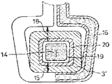
제3도는 분배용기 주입구조와, 수평방향으로 배열된 장축을 가진 연속 주조용 주형을 도시한 수직단면도.3 is a vertical sectional view showing a dispensing vessel injection structure and a continuous casting mold having a long axis arranged in the horizontal direction.
제4도는 제3도의 IV-IV선을 따라 절취하여 도시한 단면도.4 is a cross-sectional view taken along the line IV-IV of FIG.
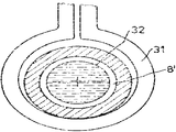
제5도는 연속 주조용 주형에서의 코일 배열 상태의 다른 실시예를 도시한 도면.5 shows another embodiment of coil arrangement in a continuous casting mold.
본 발명은 용융 금속을 주입구조와 작동 가능하게 연결시킨 말단 개구식 주형내에 내화 분배용기의 주입구조를 통하여 주조하거나 용출시키는 밀폐주입 또는 용출장치의 신규의 개량된 연속 금속 주조 장치에 관한 것이다.The present invention relates to a novel and improved continuous metal casting device for a hermetic injection or elution device which casts or elutes molten metal through an injection structure of a refractory dispensing vessel in a terminal opening mold operably connected to the injection structure.
주입구조의 대표적인 것으로는 주입튜브, 노즐, 스터드(stud), 홈통형 등과 같은 형태들이 있다. 말단 개구식 또는 연속주조용 구형으로써 금속을 연속적으로 주조하는 동안, 용융된 금속은 개방주입식 또는 밀폐 주입식으로 주입된다. 일반적으로 수직식 및 아아치형 연속 주조장치는 개방주입식으로 작동된다. 즉 분배용기와 말단개구식 주형간에 물리적인 연결을 하지 않는다. 다른 한편, 수평식 연속 주조장치는 대부분 밀폐 주입식으로 작동하도록 설계되어 있다. 이 경우, 분배 용기의 내화부는 맡단개구 또는 연속 주조용 주형의 주입 또는 용출구 측과 연결된다. 밀폐식 주입장치는 개방식 주입장치보다 최소한 다음과 같은 잇점을 제공한다. 첫째, 분배용기와 말단개구식 주형 사이에 공기 중의 산소와 주조용 금속의 접촉을 전적으로 배제할 수 있다. 또한, 주형내의 용융주조의 수위를 조절할 필요가 없다.Typical examples of the injection structure include shapes such as an injection tube, a nozzle, a stud, and a trough. During continuous casting of the metal as a spherical opening or continuous casting sphere, the molten metal is injected by open injection or by closed injection. Normally vertical and arch continuous casting machines are operated by open injection. That is, no physical connection is made between the dispensing vessel and the end-opening mold. On the other hand, horizontal continuous casting devices are designed to operate mostly in closed injection. In this case, the refractory portion of the dispensing container is connected to the injection or elution side of the bed opening or the continuous casting mold. Closed injection devices offer at least the following advantages over open injection devices: First, contact between the oxygen in the air and the casting metal can be entirely excluded between the dispensing vessel and the end-opening mold. In addition, there is no need to adjust the level of the molten casting in the mold.
1973년 12월 6일자로 허여된 독일연방공화국 특허 제1,558,224호에는 분배용기가 수평식 주형과 연결되어있는 수평식 연속 주조장치에 대해서 설명되어 있다. 이 배열에서, 용융된 금속은 공기의 유입없이 분배용기에서 주형으로 유입되며, 용융금속의 유속은 스트랜드의 회수속도에 의해서 조절된다. 액상의 금속은 제일 먼저 주형내에서 고화되기 시작하지 않고, 주형과 분배용기의 외부개구 사이에 있는 연결판 부분에서 미리 고화된다. 이것은 분배용기의 주입구조의 벽에, 특히 주입튜브의 벽에 금속이 용착 또는 고정되게 하고, 연속 주조용 스트랜드에 따라서 회수로울에 의해서 생긴 저면 유동의 결과로 이미 고형화된 스트랜드 주위에서 열구가 생기게 된다. 이것은 주조 동작을 상당히 방해하여 최종 주조생성물에서 주요 물질을 못쓰게 한다. 주형의 출구쪽의 엷은 스트랜드판 또는 각판에서 형성되는 열구로 인하여, 상류에 배열된 분배용기를 완전히 비울 수 있는 금속 파괴현상을 제거할 수가 없다. 분배용기의 출구내에 금속이 용착되면 이 연결선이 신속하게 파손된다. 그러므로 주조과정의 기간을 단축시킨다. 이 때문에, 수평식 주형으로써 스트랜드를 연속적으로 주조하는 기술은, 물질과 이러한 연결선 또는 장치의 설계를 상당히 개선했음에도 불구하고, 공업적으로 실시하는데 광범위하게 이용되지 못하고 있다.German Patent No. 1,558,224, issued December 6, 1973, describes a horizontal continuous casting device in which a dispensing vessel is connected with a horizontal mold. In this arrangement, the molten metal enters the mold from the distribution vessel without introducing air, and the flow rate of the molten metal is controlled by the rate of recovery of the strands. The liquid metal does not first start to solidify in the mold, but is already solidified in the connecting plate section between the mold and the outer opening of the dispensing vessel. This causes metal to be deposited or fixed on the wall of the injection structure of the dispensing vessel, in particular on the wall of the injection tube, resulting in fissures around the strands which have already solidified as a result of the bottom flow caused by the recovery roll along the continuous casting strand. . This significantly interferes with the casting operation, leaving the main material in the final casting product. Due to the thin strands on the outlet side of the mold or the fissures formed in each plate, it is not possible to eliminate the metal breakage phenomenon which can completely empty the distribution vessels arranged upstream. If the metal is deposited in the outlet of the dispensing vessel, this connection line is quickly broken. Therefore, the casting process is shortened. For this reason, the technique of continuously casting strands as horizontal molds has not been widely used for industrial practice, although the material and the design of such connecting lines or devices have been significantly improved.
또한 1976년 10월 26일자로 허여된 미합중국 특허 제3,987,840호에는 수평식 연속 주조방법에 대해 설명되어 있다. 이 특허에서는 금속이 분배용기로부터 인도되어 내화물, 노즐형, 상당히 넓어지거나 확대된 연결선에 의해서 연속적인 주조용 주형으로 유입된다.U.S. Patent No. 3,987,840, issued October 26, 1976, also describes a horizontal continuous casting process. In this patent, the metal is led from the dispensing vessel and introduced into the continuous casting mold by refractory, nozzle type, significantly widened or enlarged connecting lines.
액상의 금속은 이러한 노즐형 연결선 내의 전자기력의 영향을 받게 된다. 이 전자기력은 금속 스트랜드의 주위에서 이동방향으로 액상 또는 용융된 금속을 가속화시킨다. 노즐형의 넓어지거나 확대된 부분내의 먼저 형성되어 가속화된 금속의 흐름은 신속히 확대된 주형의 단면내에 자유링 형태의 공간을 만들게 되어, 안전한 요철면(meniscus) 또는 옥조수위의 혜택을 받게 된다. 노즐형 연결선을 따라서 전자기력을 발생시키는 장치는 선상 모터의 고정자에 대응한다. 이것은 다상전류에 의해서 기력을 갖게 되며 이동 전자파를 발생시킨다. 자유링 형태의 공간 또는 환상 부분에는 다수의 홈에 의해서 압력하에 불활성 기체가 유입된다. 불활성 기체의 압력은 이러한 지역에서 최소한 최대 강정전압(ferrostatic pressure)과 동일하다. 이와 같은 복잡한 단계와 또한 연결선 내의 용융금속의 축방향 가속화를 이용함에도 불구하고, 링형태의 공간내의 압력충격은 그 장치를 정지시킬 때나 링형태의 공간내의 여러가지 스트랜드의 회수운동을 방해시킬 때 완전히 방지될 수 없다. 더구나 스트랜드의 저면 또는 표면에 비해서 스트랜드의 상면에서 강정전압이 감소되기 때문에 압축 불활성 기체가 유동되는 스트랜드에 동반될 수 있다. 한편 이것은 링형태의 공간내에서 생기는 부수적인 방해가 생기게 하고, 다른 한편으로는 특히 주조용 스트랜드의 표면에서 스트랜드의 결함 또는 결점을 발생시킨다. 부수적으로 전술한 금속용착현상이 노즐형 연결선의 말단부에서 전술한 결함을 따라 생길수 있다.The liquid metal is affected by the electromagnetic forces in these nozzle-type connections. This electromagnetic force accelerates the liquid or molten metal in the direction of movement around the metal strands. The first, accelerated flow of metal in the widened or enlarged portion of the nozzle type creates a free-ring space in the cross section of the enlarged mold, benefiting a safe meniscus or oxen level. The device for generating electromagnetic force along the nozzle-type connection line corresponds to the stator of the linear motor. It is energized by polyphase currents and generates moving electromagnetic waves. Inert gas is introduced into the space or the annular portion of the free ring form under pressure by a plurality of grooves. The pressure of the inert gas is at least equal to the maximum ferrostatic pressure in this region. Despite this complex step and also the use of axial acceleration of the molten metal in the connecting line, pressure shocks in the ring-shaped space are completely prevented when the device is stopped or when disturbing the recovery of various strands in the ring-shaped space. Can't be. Furthermore, since the constant static voltage is reduced at the top of the strand as compared to the bottom or the surface of the strand, the compressed inert gas can be entrained in the flowing strand. On the one hand this leads to incidental disturbances occurring in the ring-shaped space, on the other hand, creating defects or defects of the strands, especially on the surface of the casting strand. Incidentally, the above-mentioned metal welding phenomenon may occur along the above-described defects at the distal end of the nozzle type connecting line.
또한 1979년 3월 27일자로 허여된 미합중국 특허 제4,146,078호와, 미합중국 특허 제4,244,796호에는, 주조하는 등안 용융된 금속에 따라서 작용하는 전자기력을 이용하는 장치와 기술에 대해서 일예로서 설명되어있다.In addition, US Pat. No. 4,146,078 and US Pat. No. 4,244,796, issued March 27, 1979, describe, by way of example, devices and techniques that utilize electromagnetic forces acting on molten metal, such as casting.
또 다수의 스트랜드를 동시에 주조하는 기술은 1971년 8월 17일자로 허여된 카나다 특허 제878,383호에 기술되어 있는데, 이 특허에는 통상의 분배용기와 기밀형태로 연결된 수직배향 연속 주조용 주형의 배열방법에 대해서 설명되어 있다. 이 기술에서, 응용된 금속은 저부 주입노즐에 의해서 연속 주조용 주형으로 유입된다. 내화 분배용기 주입구 또는 개구와 냉각된 주형사이에서는 선택적으로 가스쿠션과 작동하거나 이 가스쿠션이 없이 작동할 수도 있다. 이 수직 배열 주형에 의하면, 내화 분배용기 주입구와 냉각된 말단 개구식 주형 사이의 수평식 연속 주조기술로부터 이 기술분야에 공지된 방해가 생긴다. 주형과 이러한 노즐사이에 연장된 구입 노즐과 가스 쿠션을 사용함에도 불구하고, 주조 조건이 변하는 동안 노즐에서 금속용착물이 형성되어 장치에 손상을 끼치게 된다. 그러므로 이 방법은 공업적으로 이용되지 못하고 있다.A technique for casting multiple strands simultaneously is described in Canadian Patent No. 878,383, issued August 17, 1971, which discloses a method of arranging a mold for vertically oriented continuous casting in a hermetically sealed container. Is described. In this technique, the applied metal is introduced into the continuous casting mold by the bottom injection nozzle. The refractory dispensing container inlet or opening and the cooled mold may optionally be operated with or without a gas cushion. With this vertically arranged mold, a disturbance known in the art arises from the horizontal continuous casting technique between the refractory dispensing vessel inlet and the cooled end opening mold. In spite of the use of an extended purchase nozzle and gas cushion between the mold and such a nozzle, metal deposits are formed on the nozzles during casting conditions, which damage the apparatus. Therefore, this method is not used industrially.
본 발명의 주목적은 선행기술 구조의 전술한 결점과 한계점을 시정하는 방법으로 밀폐식 주입장치내에서 금속 스트랜드를 연속적으로 주조하는 신규의 개량된 장치를 제공하는 것이다.It is a primary object of the present invention to provide a novel and improved apparatus for continuously casting metal strands in a hermetic injection device in a way to correct the aforementioned drawbacks and limitations of the prior art structure.
본 발명의 다른 목적은 주입구와 같은 내화 분배용기의 주입구조와 주형사이의 연결부에서 생기는 전술한 단점, 특히 금속의 용착현상, 스트랜드의 결점, 금속의 파열 등과 같은 문제점들을 매우 간단한 장치를 이용함으로써 해결하는 것이다.Another object of the present invention is to solve the above-mentioned shortcomings caused by the connection between the injection structure of the refractory dispensing container such as the inlet and the mold, in particular, problems such as welding of the metal, defects of the strands, rupture of the metal, etc. by using a very simple device. It is.
본 발명의 또다른 목적은 통상의 용기, 특히 턴디시(tundish)로부터 밀폐식 주조 또는 주입장치에 의해서 용융된 금속을 공급받을 수 있는, 수평 또는 수직으로 장치한 주형을 가진 다중 스트랜드의 연속 주조장치를 작동시키기 위한 경제적인 주조방법을 창안하는 것이다.Another object of the present invention is a continuous casting apparatus of multiple strands having horizontally or vertically installed molds, which can be supplied with molten metal from a conventional vessel, in particular tundish, by a closed casting or injection device. It is to create an economical casting method to operate.
본 발명의 또 다른 목적은 가능한 주조시간을 연장하여 이러한 연속 주조장치의 배출 또는 생산능력을 향상시키는 것이다.It is a further object of the present invention to improve the discharge or production capacity of such continuous casting apparatus by extending the casting time as much as possible.
상세한 설명에 의해서 더 명백해질 본 발명의 상기 목적 및 그외의 다른 목적을 실시하기 위해서, 본 발명은 수축 또는 용융수축 전자장을 사용하여 분배용기의 주입장치와 말단 개구식 주형사이의 연결판 부분에서 주형 주입구의 벽으로부터 용융물질이 계속적으로 분리되게 한다.In order to achieve the above and other objects of the present invention which will become more apparent from the detailed description, the present invention provides a mold in the connection plate portion between the dispensing device and the dispensing mold of the dispensing vessel using a contraction or melt shrinking electromagnetic field. The molten material is continuously separated from the wall of the inlet.
본 발명에 따른 장치는 분배용기의 주입구조와 말단개구식 주형 사이의 연결판 부분에, 금속용융물을 수축시키는 전자기 코일이 배열된 것을 특징으로 한다. 특히, 전자기 코일을 연결판의 주형 쪽에, 즉 주형의 상면 또는 부근의 연결판의 측면에 배열한 경우에 유익하다.The device according to the invention is characterized in that an electromagnetic coil is arranged in the connecting plate portion between the dispensing structure of the dispensing vessel and the end opening mold. In particular, it is advantageous when the electromagnetic coil is arranged on the mold side of the connecting plate, that is, on the side of the connecting plate near or on the upper surface of the mold.
본 발명은 간단한 공정단계를 이용하고 가격이 저렴한 장치를 이용하여, 수직 및 수평식으로 장치한 주형으로 연속적인 주조를 할 때 밀폐식 주조장치의 잇점을 개발할 수 있다. 즉 금속의 용착 또는 응결, 스트랜드의 결점 또는 결함 및 금속파열 등과 같은 이 기술분야의 공지된 결점이 효과적으로 방지될 수 있다. 주입구 또는 튜브와 같은 분배용기 주입구조내의 마모가 상당히 줄어들기 때문에, 주조용 국자(ladle)로부터 더 오래 계속적으로 주조를 행할 수 있어, 시간의 낭비를 상당히 줄이며 정비 비용을 점감할 수 있는 잇점이 있다. 수직으로 장치한 말단개구식 연속 주조용 주형을 사용할 때, 본 발명의 방법은 스트랜드들 사이에 더 작은 공간을 갖고 있고 통상의 분배용기로부터 공급되는 다수의 스트랜드가 통상의 회수장치에 의해서 구동될 수 있고 분배용기 내의 욕조수위 또는 요철면을 관리하는 것만이 필요한 더욱 간단한 연속 주조장치를 설계할 수 있다. 공지된 밀폐식 주조장치로 아직 완전하게 해결하지 못한 다른 문제점은 주형내에 윤활유를 주입시켜야 한다는 것이다. 본 발명의 다른 유익한 형태에 따르면, 링형 또는 환상의 공간내로 스트랜드를 위하여 윤활유를 유입시킬 수 있는 링형 또는 환상의 공간내의 진공상태를 이용하여 일정한 윤활유의 공급을 실현시킬 수가 있다. 액체, 반죽 또는 가루형 윤활제를 사용하는 대신에, 예를 들어 링형 공간과 주형내에 각각 진공의 작용에 의해서 첨가제를 첨가하거나 첨가하지 않고서 비산화기체를 유입시킬 수 있다.The present invention can develop the benefits of a hermetically sealed casting machine when using a simple process step and using an inexpensive device to continuously cast the mold vertically and horizontally. That is, defects known in the art such as welding or condensation of metals, defects or defects of strands, and metal rupture can be effectively prevented. Since the wear in the dispensing container injection structure, such as the inlet or the tube, is significantly reduced, it is possible to continuously cast longer from the casting ladle, which significantly reduces waste of time and reduces maintenance costs. . When using vertically open end-type continuous casting molds, the method of the present invention has a smaller space between the strands and a number of strands supplied from a conventional dispensing vessel can be driven by a conventional recovery device. It is possible to design simpler continuous casting devices that only need to manage the level of the bath or uneven surface in the dispensing vessel. Another problem that has not yet been completely solved with the known hermetic casting apparatus is the need to inject lubricant into the mold. According to another advantageous aspect of the present invention, it is possible to realize the supply of constant lubricant oil by using a vacuum in the ring or annular space capable of introducing the lubricant for the strand into the ring or annular space. Instead of using liquid, kneading or powdered lubricants, non-oxidizing gases can be introduced, for example, with or without the addition of additives by the action of vacuum, respectively, in the ring-shaped space and the mold.
내화 분배용기 주입구의 마손은 본 발명의 다른 형태에 따라서 전자기 코일이 연결판의 양측에 배열된 경우에 부수적으로 감소될 수 있다.The wear and tear of the refractory distribution container inlet can be incidentally reduced when the electromagnetic coil is arranged on both sides of the connecting plate according to another aspect of the present invention.
분배용기의 주입구 또는 동등한 주입구조를 통하여 금속의 유속을 감소시키고 또한 수축 또는 집결효과를 증가시키기 위하여, 본 발명은 또한 연결판 부분에서 같은 크기로 되도록 분배용기 주입구의 출구와 주형의 입구를 선택하고 부수적으로 전자장에 의해서 출구로부터 일정 거리에서 용융된 금속을 유지시키는 것을 제안한다.In order to reduce the flow rate of the metal and increase the shrinkage or gathering effect through the inlet of the distribution vessel or the equivalent injection structure, the present invention also selects the outlet of the distribution vessel inlet and the inlet of the mold to be the same size at the connecting plate part. Incidentally, it is proposed to keep the molten metal at a certain distance from the outlet by the electromagnetic field.
수직으로 배열된 주형의 경우에는, 연결판 부분에서, 분배용기 구입구의 출구 또는 유출구가 주형의 입구보다 더 적은 것이 유익하다. 대략 수직 또는 수평방향으로 배향된 주형 축을 가진 연속 주조장치의 경우에, 중공형 주형의 구획 또는 동공의 주위에 집결되도록 전자기 코일을 배치할 수 있다. 말단 개구식 주형의 수평장축 아래의 전자기 코일과 중공형 주형의 구획사이의 공간이 주형의 장축 위에 위치한 중공형 주형의 구획으로부터 전자기 코일의 공간보다 적으면 수평식 연속 주조장치의 경우에 특히 유익하다. 이러한 배열에 의하면, 상이한 강정전압을 스트랜드의 높이를 통하여 적당히 조절할 수 있다. 상이한 강정전압의 결점을 시정하기 위한 다른 해결책에 따르면, 둥근형태 또는 단면 부분을 가진 스트랜드 주조 중에, 타원형 또는 편심형으로 배열된 원형전자기 코일을 사용하는 것이 본 발명에 의해서 시도된다. 이 전자기 코일은 이러한 장축위의 위치에서 보다 중공형 주형 부분으로부터 더 작은 공간을 주형의 수평장축 아래에 갖고 있다.In the case of molds arranged vertically, in the connecting plate part, it is advantageous that the outlet or outlet of the dispensing container purchase port is smaller than the inlet of the mold. In the case of a continuous casting apparatus having a mold axis oriented in a substantially vertical or horizontal direction, the electromagnetic coil may be arranged to be collected around a section or pupil of the hollow mold. It is particularly advantageous in the case of a horizontal continuous casting machine if the space between the section of the hollow mold and the hollow coil below the horizontal long axis of the end opening mold is less than the space of the electromagnetic coil from the section of the hollow mold located above the long axis of the mold. . According to this arrangement, different constant voltages can be appropriately adjusted through the height of the strands. According to another solution for correcting the shortcomings of different constant voltages, it is attempted by the present invention to use circular electromagnetic coils arranged in elliptical or eccentric form during strand casting with rounded or cross-sectional portions. This electromagnetic coil has less space below the mold's horizontal major axis than at the hollow mold part at this position on the major axis.
본 발명의 다른 형태에 따르면, 연속 주조용 주형의 열 전도성에 비해서 감소된 열전도성을 가진 주형을 내화 분배용기의 주입구조 또는 주입구와 연속 주조용 주형 사이에 배열한 경우에 스트랜드 표면의 성질을 개량할 수 있다. 전자장의 수축작용은 주형부분이 적당히 낮은 열전도성을 가진 상자 성물질로 형성된 경우에 증공형 주형 부분내에서 부수적으로 개량될 수 있다.According to another aspect of the present invention, the properties of the strand surface are improved when a mold having a reduced thermal conductivity as compared to the thermal conductivity of the continuous casting mold is arranged between the injection structure of the refractory dispensing container or the inlet and the continuous casting mold. can do. The contraction of the electromagnetic field can be concomitantly improved in the thickened mold part when the mold part is formed of a paramagnetic material with moderately low thermal conductivity.
본 발명을 첨부된 도면에 의해서 상세히 설명하면 다음과 같다.The present invention will be described in detail with reference to the accompanying drawings.
제 1도는 내화 분배용기의 주입구조(2)를 주입구 또는 튜브의 형태로 도시한 것으로, 이 주입구는 대략 수직으로 배치된 주형 장축(1)을 가진 냉각된 말단개구 또는 연속 주조용 주형(3)과 연결되어 있다. 분배용기 주입구조(2)와 동작적으로 결합된 냉각된 말단 개구식 주형(3)과 함께, 분배 용기 주입구조(2)는 밀폐식 주입 또는 티밍(teeming)장치를 구성한다.1 shows the
말단 개구식 주형(3)과 용기 주입구조(2)의 사이에는 연결판(4)가 있다. 이 연결판(4)의 주형쪽에는 연속 또 말단 개구식 주조용 주형을 통하여 유동하는 강철과 같은 금속의 수축 또는 응집(7)을 발생시키는 전자기 코일(6)을 구성하는 전자기 장치가 배열되어 있다. 전자기 코일(6)의 전자장에 의해서 생기는 수축 또는 핀치(pinch) 효과로 인하여, 자유링형 또는 환상 공간(8)이 형성되므로, 연결판(4)의 부분에서는 유입되는 강철이 연속 주조용 주형(3)의 벽면과 접촉하지 않게 된다. 용기 주입구조(2)는 설명하지 않은 종래의 분배 또는 주조용기의 일부분을 구성한다. 일반적으로, 특정하게 설명하지 않은 유사한 표준지지 안내 부재 또는 로울러 에이프련(apron)과 연속적으로 또는 간헐적으로 주조 스트랜드를 회수하기 위한 스트랜드 회수 유니트가 말단 개구식 주형(3)을 따라서 배치된다. 연결판(4)의 지역에 있는 주입구조 또는 주입구(2)의 출구 또는 배출구(5)의 크기는 주형입구(11)보다 작다. 이에 관련해서, 용융된 금속에 따라서 전자기력을 나타내기 위한 전자기 장치가, 예를 들어 1979년 5월 29일자로 허여된 미합중국 특허 제4,156,451호와 같은 본 기술분야에 공지되어 있기 때문에, 본 발명은 전자기 핀치 또는 수축효과를 발생시키기 위한 장치의 특정 구조에 한정되지 않는다.There is a connecting plate 4 between the
제 2도에서는 동일 또는 유사한 구조를 표시하기 위하여 제 1도에서 사용한 것과 동일한 참조번호를 사용하였다. 이 도면에서, 분배용기 주입구조(2)의 출구 또는 배출구(10)은 주형 입구(11)과 동일한 크기로 연결판(4)의 부분에 구성되어 있다. 부수적으로, 전자기 코일(6')는 연결판(4)의 양측에 배열되어 있다. 전자기 코일(6')는 주입구조 또는 주입구(2)의 출구(10)으로부터 용융된 금속을 분리하여 유지시키는 전자장을 한번 더 발생시킨다. 결과적으로, 참조번호(7)로 표시된 수축 또는 핀치작용이 형성되어, 출구(10)과 주형의 입구(11)에서 용융금속(13)이 접촉되지 않도록 전자장에 의해서 작용하는 용융된 금속을 결속시키게 된다. 이렇게 형성된 링형 또는 환상공간(8')의 형태는 제 1도의 링형 공간(8)과 상이하다.In FIG. 2, the same reference numerals as used in FIG. 1 are used to indicate the same or similar structures. In this figure, the outlet or
제 3도와 제 4도의 수평식 연속 주조장치에 의하면, 말단 개구식 또는 연속 주조용 주형(3')의 장축(14)는 대략 수평방향으로 연장되도록 배치된다. 말단 개구식 주형(3')의 수평장축(14) 아래의 수냉식 전자기 단권선 코일(16)과 중공형 주형부분(19) 사이의 공간(15)는 이러한 장축(14) 위의 공간(18)보다 더 작다. 연속주조 말단개구식 주형(3')의 입구쪽에는 구리로 형성된 연속 주조용 주형(3')에 비해서 열전도성이 낮은 내면을 가진 주형부분(20)이 제공되어 있다. 이 선형 주형부분 또는 내면(20)은 일예를 들어 스텐레스 강철과 같은 적당한 성자성 물질로부터 유익하게 제조된다. 수축(7)을 저지시킬 수 있는 자유링형 공간(8')내에 진공이 형성되지 않게 하기 위해서, 불활성 기체는 링형 또는 환상 공간(8')내로 감압밸브(23)에 의해서 공급홈과 같은 미세 공급장치(24)를 통하여 용기(22)로부터 공급된다. 이 압력은 대략 대기압 상태로 조절되므로, 용융된 금속(13)의 강정전압보다 작게 된다. 링형 공간(8')내에 이루어진 진공상태는 주조용 스트랜드를 발생시키는 용융된 금속내에 적당한 윤활제를 유입시키는데 유리하게 사용될 수 있다.According to the horizontal continuous casting apparatus of FIG. 3 and FIG. 4, the
마지막으로, 제 5도에는 참조번호(32)로 표시된 원형 스트랜드 단면 주위에 배치된 약간의 타원형 전자기 코일(31)을 사용하는 배열이 도시되어 있다.Finally, FIG. 5 shows an arrangement using some elliptical
전자기 코일의 설계 및 전력, 주파수 등의 선택은 연결판 부분에서 금속의 용융물이 용융 핀치 또는 용융수축 전자장에 의해서 분배용기 주입구로부터 또는 주형의 벽으로부터, 즉 출구 끝에서의 주입구조의 벽으로부터 분리 관계로 유지되도록 될 수 있다.The design of the electromagnetic coil and the choice of power, frequency, etc. are related to the separation of the melt of the metal in the connecting plate part from the dispensing vessel inlet by the melt pinch or melt-shrinkable field or from the wall of the mold, ie from the wall of the injection structure at the outlet end. May be maintained.
제 2도에 일예로 도시한 바와 같은 장치에 의해서 직경이 100mm인 원형 스트랜드를 주조하기 위해서는 다음과 같은 매개변수를 일예로써 사용할 수가 있다.In order to cast a circular strand having a diameter of 100 mm by the apparatus as shown in FIG. 2 as an example, the following parameters can be used as an example.

제 3도 및 제 4도에 도시한 형태의 장치를 사용하여 150mmψ의 4각형 스트랜드를 주조하기 위하여, 다음과 같은 매개 변수를 선택하였다.In order to cast a 150 mm square hexagonal strand using the apparatus of the type shown in FIGS. 3 and 4, the following parameters were selected.

본 발명의 장치는 여러가지 금속에 유익하게 적용될 수 있다. 특히, 철-탄소 합금을 주조할 수도 있다. 전기 코일의 자유로운 설계 가능성으로 인하여, 상이한 단면을 가진 스트랜드에도 본 발명의 기술을 적용할수 있다.The apparatus of the present invention can be advantageously applied to various metals. In particular, it is also possible to cast iron-carbon alloys. Due to the free design possibilities of the electric coil, the technique of the present invention can be applied to strands having different cross sections.
Claims (1)
Applications Claiming Priority (2)
| Application Number | Priority Date | Filing Date | Title |
|---|---|---|---|
| CH5347/80-2 | 1980-07-11 | ||
| CH5347/80A CH648500A5 (en) | 1980-07-11 | 1980-07-11 | METHOD AND DEVICE FOR CONTINUOUSLY casting metal in a closed pouring system. |
Publications (2)
| Publication Number | Publication Date |
|---|---|
| KR830005941A KR830005941A (en) | 1983-09-14 |
| KR840002039B1 true KR840002039B1 (en) | 1984-11-06 |
Family
ID=4292056
Family Applications (1)
| Application Number | Title | Priority Date | Filing Date |
|---|---|---|---|
| KR1019810002475A KR840002039B1 (en) | 1980-07-11 | 1981-07-08 | Apparatus for continuous casting of metalic strands in a closed pouring system |
Country Status (10)
| Country | Link |
|---|---|
| US (1) | US4450892A (en) |
| EP (1) | EP0043987B1 (en) |
| JP (1) | JPS5744454A (en) |
| KR (1) | KR840002039B1 (en) |
| AT (1) | ATE6476T1 (en) |
| BR (1) | BR8104428A (en) |
| CA (1) | CA1176427A (en) |
| CH (1) | CH648500A5 (en) |
| DE (1) | DE3162508D1 (en) |
| ES (1) | ES8205141A1 (en) |
Families Citing this family (17)
| Publication number | Priority date | Publication date | Assignee | Title |
|---|---|---|---|---|
| JPS57209752A (en) * | 1981-06-17 | 1982-12-23 | Kawasaki Heavy Ind Ltd | Horizontal continuous casting installation |
| DE3131353A1 (en) * | 1981-08-07 | 1983-02-24 | Neue Technik Entwicklung und Vertrieb F. Block, 5106 Roetgen | "METHOD AND DEVICE FOR SEALING THE GAP BETWEEN RELATIVELY MOVING DEVICES" |
| DE3136847C1 (en) * | 1981-09-16 | 1982-10-28 | Korf Engineering GmbH, 4000 Düsseldorf | Method and device for horizontal continuous casting of liquid metals, in particular steel |
| JPS5886959A (en) * | 1981-11-18 | 1983-05-24 | Kawasaki Heavy Ind Ltd | Horizontal continuous casting method |
| KR870000714B1 (en) * | 1981-11-18 | 1987-04-09 | 하세가와 겐고오 | Horizontal continuous casting method |
| CH665369A5 (en) * | 1984-03-07 | 1988-05-13 | Concast Standard Ag | METHOD FOR CONTROLLING THE FLOW OF A METAL MELT IN CONTINUOUS CASTING, AND A DEVICE FOR IMPLEMENTING THE METHOD. |
| JPS61111747A (en) * | 1984-11-07 | 1986-05-29 | Nippon Kokan Kk <Nkk> | Continuous casting device for steel plate |
| JPS61186150A (en) * | 1985-02-13 | 1986-08-19 | Sumitomo Light Metal Ind Ltd | Casting method by suspension in electromagnetic field |
| US4693299A (en) * | 1986-06-05 | 1987-09-15 | Westinghouse Electric Corp. | Continuous metal casting apparatus |
| US4741383A (en) * | 1986-06-10 | 1988-05-03 | The United States Of America As Represented By The United States Department Of Energy | Horizontal electromagnetic casting of thin metal sheets |
| US4842170A (en) * | 1987-07-06 | 1989-06-27 | Westinghouse Electric Corp. | Liquid metal electromagnetic flow control device incorporating a pumping action |
| US4846255A (en) * | 1987-10-28 | 1989-07-11 | The United States Of America As Represented By The United States Department Of Energy | Electromagnetic augmentation for casting of thin metal sheets |
| JPH04197559A (en) * | 1990-11-27 | 1992-07-17 | Nkk Corp | Continuous casting method for steel |
| US5379828A (en) * | 1990-12-10 | 1995-01-10 | Inland Steel Company | Apparatus and method for continuous casting of molten steel |
| US5494095A (en) * | 1992-04-08 | 1996-02-27 | Inland Steel Company | Apparatus for continuous casting of molten steel |
| IT1316299B1 (en) * | 2000-01-26 | 2003-04-10 | Danieli Off Mecc | PROCEDURE AND DEVICE TO IMPROVE THE QUALITY OF CONTINUOUSLY CAST CASTINGS |
| DE10210430A1 (en) * | 2002-03-09 | 2003-09-18 | Sms Demag Ag | Device for hot dip coating of metal strands |
Family Cites Families (15)
| Publication number | Priority date | Publication date | Assignee | Title |
|---|---|---|---|---|
| CA878383A (en) * | 1971-08-17 | Schloemann Aktiengesellschaft | Mold for the simultaneous continuous casting of a plurality of individual strands | |
| DE1558224C3 (en) * | 1967-06-24 | 1973-12-06 | Theodor Prof. Dr.-Ing. 3000 Hannover-Kirchrode Rummel | Method and device for the horizontal continuous casting of molten metals, in particular steel |
| US3547182A (en) * | 1968-02-21 | 1970-12-15 | Nat Steel Corp | Continuous casting apparatus |
| US3612149A (en) * | 1968-09-05 | 1971-10-12 | Concast Inc | Continuous casting method |
| JPS5027028B1 (en) * | 1969-11-19 | 1975-09-04 | ||
| US3630266A (en) * | 1969-11-21 | 1971-12-28 | Technicon Corp | Continuous casting process |
| US3721287A (en) * | 1971-11-19 | 1973-03-20 | Aluminum Co Of America | Method of continuously casting plate with textured surface |
| FR2252154B1 (en) * | 1973-11-28 | 1976-12-03 | Siderurgie Fse Inst Rech | |
| FR2316026A1 (en) * | 1975-07-04 | 1977-01-28 | Anvar | ELECTROMAGNETIC DEVICE FOR CONTAINING LIQUID METALS |
| JPS5232824A (en) * | 1975-09-09 | 1977-03-12 | Nippon Steel Corp | Method of casting metal melts |
| DE2722969A1 (en) * | 1976-05-24 | 1977-12-15 | Bailey Ltd C H | Floating dock with several pontoons - has all or some interconnected via horizontal pivots at right angles to dock length |
| CH604974A5 (en) * | 1976-12-17 | 1978-09-15 | Concast Ag | |
| FR2397251A1 (en) * | 1977-07-12 | 1979-02-09 | Anvar | METHOD AND DEVICE FOR DIRECTING, IN THE ABSENCE OF WALLS, LIQUID METALLIC VEINS, IN PARTICULAR FOR CENTERING, GUIDING OR CHECKING THEIR CIRCULAR SHAPE |
| CH625728A5 (en) * | 1977-12-27 | 1981-10-15 | Concast Ag | |
| US4156451A (en) * | 1978-02-07 | 1979-05-29 | Getselev Zinovy N | Continuous or semi-continuous metal casting method |
-
1980
- 1980-07-11 CH CH5347/80A patent/CH648500A5/en not_active IP Right Cessation
-
1981
- 1981-06-29 US US06/278,414 patent/US4450892A/en not_active Expired - Fee Related
- 1981-07-01 EP EP81105098A patent/EP0043987B1/en not_active Expired
- 1981-07-01 AT AT81105098T patent/ATE6476T1/en not_active IP Right Cessation
- 1981-07-01 DE DE8181105098T patent/DE3162508D1/en not_active Expired
- 1981-07-08 KR KR1019810002475A patent/KR840002039B1/en active
- 1981-07-09 CA CA000381384A patent/CA1176427A/en not_active Expired
- 1981-07-10 JP JP56107201A patent/JPS5744454A/en active Granted
- 1981-07-10 BR BR8104428A patent/BR8104428A/en unknown
- 1981-07-10 ES ES504334A patent/ES8205141A1/en not_active Expired
Also Published As
| Publication number | Publication date |
|---|---|
| DE3162508D1 (en) | 1984-04-12 |
| EP0043987B1 (en) | 1984-03-07 |
| ATE6476T1 (en) | 1984-03-15 |
| EP0043987A1 (en) | 1982-01-20 |
| CH648500A5 (en) | 1985-03-29 |
| ES504334A0 (en) | 1982-06-01 |
| KR830005941A (en) | 1983-09-14 |
| US4450892A (en) | 1984-05-29 |
| JPS5744454A (en) | 1982-03-12 |
| CA1176427A (en) | 1984-10-23 |
| BR8104428A (en) | 1982-03-30 |
| JPS6257420B2 (en) | 1987-12-01 |
| ES8205141A1 (en) | 1982-06-01 |
Similar Documents
| Publication | Publication Date | Title |
|---|---|---|
| KR840002039B1 (en) | Apparatus for continuous casting of metalic strands in a closed pouring system | |
| US3605865A (en) | Continuous casting apparatus with electromagnetic screen | |
| CA1097880A (en) | Horizontal continuous casting method and apparatus | |
| US3519059A (en) | Method of vacuum slag refining of metal in the course of continuous casting | |
| JP5916942B2 (en) | Continuous casting equipment | |
| US3987840A (en) | Method and apparatus for continuously casting of metal in horizontal direction | |
| US3669181A (en) | Pouring apparatus with submerged deflector plates for continuous casting | |
| US4456054A (en) | Method and apparatus for horizontal continuous casting | |
| US3903955A (en) | Horizontal continuous casting apparatus with reciprocatory gate | |
| EP0090490B1 (en) | A plant for the production of castings in a stepwise advanced casting mould consisting of identical, flaskless mould parts | |
| JPH0470105B2 (en) | ||
| RU2296034C2 (en) | Method for treating melt metals by means of moving electric arc | |
| KR101454311B1 (en) | Hollow jet nozzle for continuous steel casting | |
| US3166803A (en) | Device for centering the stream of metal to the middle of the mould during vertical continuous casting | |
| US3788383A (en) | Apparatus for the continuous extraction of electroslag remelted metals | |
| US4478273A (en) | Stirring metal in a continuous casting mold | |
| US5887647A (en) | Decreasing contamination of molten metal prior to solidification casting | |
| US4566526A (en) | Method and apparatus for semi-horizontal continuous casting | |
| US3811490A (en) | Continuous casting of rimming steel | |
| US3545530A (en) | Horizontal continuous casting mold | |
| US3804150A (en) | Apparatus for electroslag remelting | |
| EP0290866A2 (en) | Improved discrete excitation coil producing seal at continuous casting machine pouring tube outlet nozzle/mold inlet interface | |
| JPH11291000A (en) | Continuous casting, particularly, steel continuous casting equipment | |
| US4919192A (en) | Discrete excitation coil producing seal at continuous casting machine pouring tube outlet nozzle/mold inlet interface | |
| EP0036777A1 (en) | Horizontal continuous casting machine |