KR840000210B1 - Transfer drum applicatri of narrow sting cemponent to a trie being built on a tire building drum - Google Patents
Transfer drum applicatri of narrow sting cemponent to a trie being built on a tire building drum Download PDFInfo
- Publication number
- KR840000210B1 KR840000210B1 KR1019810000053A KR810000053A KR840000210B1 KR 840000210 B1 KR840000210 B1 KR 840000210B1 KR 1019810000053 A KR1019810000053 A KR 1019810000053A KR 810000053 A KR810000053 A KR 810000053A KR 840000210 B1 KR840000210 B1 KR 840000210B1
- Authority
- KR
- South Korea
- Prior art keywords
- drum
- tire
- pair
- drums
- forming
- Prior art date
Links
Images


Classifications
-
- B—PERFORMING OPERATIONS; TRANSPORTING
- B29—WORKING OF PLASTICS; WORKING OF SUBSTANCES IN A PLASTIC STATE IN GENERAL
- B29D—PRODUCING PARTICULAR ARTICLES FROM PLASTICS OR FROM SUBSTANCES IN A PLASTIC STATE
- B29D30/00—Producing pneumatic or solid tyres or parts thereof
- B29D30/06—Pneumatic tyres or parts thereof (e.g. produced by casting, moulding, compression moulding, injection moulding, centrifugal casting)
- B29D30/08—Building tyres
- B29D30/20—Building tyres by the flat-tyre method, i.e. building on cylindrical drums
- B29D30/30—Applying the layers; Guiding or stretching the layers during application
- B29D30/3007—Applying the layers; Guiding or stretching the layers during application by feeding a sheet perpendicular to the drum axis and joining the ends to form an annular element
-
- B—PERFORMING OPERATIONS; TRANSPORTING
- B29—WORKING OF PLASTICS; WORKING OF SUBSTANCES IN A PLASTIC STATE IN GENERAL
- B29D—PRODUCING PARTICULAR ARTICLES FROM PLASTICS OR FROM SUBSTANCES IN A PLASTIC STATE
- B29D30/00—Producing pneumatic or solid tyres or parts thereof
- B29D30/06—Pneumatic tyres or parts thereof (e.g. produced by casting, moulding, compression moulding, injection moulding, centrifugal casting)
- B29D30/08—Building tyres
- B29D30/20—Building tyres by the flat-tyre method, i.e. building on cylindrical drums
- B29D30/24—Drums
- B29D2030/241—Auxiliary drums used for temporary storage of the layers before application to the building drums
Abstract
Description
제1도는 본 발명에 의한 장치의 개략적인 측면도.1 is a schematic side view of a device according to the invention.
제2도는 제1도 장치의 부분 정면도.2 is a partial front view of the first FIG. Device.
제3도 및 제4도는 제1도 및 제2도의 장치의 작업을 설명하는 개략적인 측면도.3 and 4 are schematic side views illustrating the operation of the apparatus of FIGS. 1 and 2.
본 발명은 타이어 성형에 관한 것으로서, 특히 타이어 성형 드럼 둘레에 건조(建造)시키는 중에 다수 쌍의 타이어 성형 스트립 소재를 타이어 카커스(carcass)에 적용시키기 위한 장치에 관한 것이다.TECHNICAL FIELD The present invention relates to tire shaping, and more particularly to an apparatus for applying a plurality of pairs of tire shaping strip materials to a tire carcass during drying around a tire shaping drum.
본 발명의 특징에 의하면 축에 대해 회전하도록 장치된 타이어 성형 드럼에 성형되는 타이어에 다수의 타이어 성형 소재를 적용하기 위한 장치가 제공되는 데, 상기 장치는 상기 성형 드럼 직경의 1.4 내지 2배의 직경을 가지면서 상기 성형 드럼과 축방향으로 정합되게끔 상기 축에 대해 평행하게 장치된 한쌍의 드럼을 포함하는 이송장치와, 상기 축에 대해 수직인 평면에서 상기 드럼이 상기 성형 드럼과 니프성형 관계를 유지하게끔 병치되게 되어있는 제1위치와 상기 성형드럼으로 부터 멀리 떨어진 제2위치 사이에서 이동시키기 위하여 상기 이송장치를 고정시키는 장치와, 제1타이어 성형소재 및 제2타이어 성형 소재를 상기 드럼에 각각 적용하기 위한 제1적용장치 및 제2적용장치와, 상기 각각의 제1적용장치와 제2적용장치를 상기 제2위치에서 상기 드럼과 소재 이송관계를 갖게끔 상기 평면에 대해 평행한 방향으로 이동시키고 또한 상기 드럼으로부터 멀리 이동시키도록 상기 각 제1적용장치와 제2적용장치에 제휴되는 이동장치와, 상기 드럼에 결속된 디지탈 인코더(digital encoder)를 포함하며 상기 드럼이 상기 제2위치에 있는 중에 상기 드럼의 제1각 변위에 감응해 상기 제1적용장치를 작동할 수 있게하고 상기 이송장치가 상기 제2위치에 있는 중에 이송장치의 각각의 드럼에 위치하는 각각의 제1스트립소재 위에 각각의 제2스트립소재의 일부 길이를 위치시키도록 상기 이송드럼의 제2각변위에 감응해 상기 제2적용장치를 작동할 수 있게 하는 제어장치등을 포함한다.According to a feature of the present invention there is provided an apparatus for applying a plurality of tire forming materials to a tire that is formed on a tire forming drum arranged to rotate about an axis, the apparatus having a diameter of 1.4 to 2 times the diameter of the forming drum. A transfer device including a pair of drums arranged parallel to the axis to axially mate with the forming drum, the drum being in nip forming relationship with the forming drum in a plane perpendicular to the axis; A device for fixing the transfer device to move between the first position, which is arranged to be juxtaposed to be held, and a second position away from the forming drum, and the first tire forming material and the second tire forming material to the drum, respectively. A first application device and a second application device for application, and each of the first application device and the second application device in the second position A moving device associated with each of the first and second application devices so as to move in a direction parallel to the plane and away from the drum to have a material conveying relationship with the drum, and a digital device coupled to the drum. An encoder (digital encoder) and enabling the first application device to operate in response to a first angular displacement of the drum while the drum is in the second position and the transfer device in the second position. Responsive to the second angular displacement of the transfer drum to operate a portion of the length of each second strip material over each first strip material located on each drum of the transfer device to operate the second application device. Control device, etc.
기술분야에서 숙련된 자에게 명백한 바와 같이, 본문에 예시되고 설명된 양호한 실시예는 청구범위에 한정된 발명의 정신 및 범위내에서 수많은 방식으로 수정될 수 있다.As will be apparent to those skilled in the art, the preferred embodiments illustrated and described herein may be modified in numerous ways within the spirit and scope of the invention as defined by the claims.
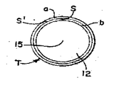
제1도 및 제2도에 도식적으로 예시된 장치(10)는 어떤 적합한 형의 타이어 성형 드럼(12)을 포함하는 데, 상기 타이어 성형 드럼은 드럼의 축방향 길이와 동일하거나 그 이상의 폭을 갖는 내부라이너와, 드럼의 축방향폭과 동일하거나 그 이상의 폭을 갖는 코드 또는 와이어로 보강된 플라이를 포함하는 다수의 소재를 연속적으로 드럼 둘레에 권취시키도록 자체축(15)에 대해 회전할 수 있다.The
라이너 및 플라이는 타이어(T)를 드럼(12)에 성형시키는 중에, 도면에는 도시되지 않은 기계적인 장치등과 같은 어떤 적합한 방식으로 타이어 성형 드럼에 권취된다.The liner and ply are wound on the tire building drum in any suitable manner, such as a mechanical device not shown in the drawing, during the shaping of the tire T on the
드럼에 대한 라이너 및 보강 플라이의 권취는 성형 드럼에 대한 단일 타이어(T)의 성형을 완료시키는 데 요구되는 시간중 상당시간을 차지한다.The winding of the liner and reinforcing plies to the drum takes up a significant amount of time required to complete the molding of a single tire T to the forming drum.
타이어 성형 시간주기의 제조효율을 개선하기 위하여, 본문에 기술되는 장치는 성형될 타이어의 둘레에 예정된 축방향 위치에서 각각 적용될 좁은 스트립의 형태를 갖는 소재쌍을 적용하므로써 개발되어 왔다.In order to improve the manufacturing efficiency of the tire forming time period, the apparatus described in the text has been developed by applying a pair of materials having the form of narrow strips to be applied respectively at predetermined axial positions around the tire to be molded.
본 실시예에 있어서는 두드러진 두 이점이 얻어진다. 첫째로는 측벽, 체이퍼(chafer)등과 같은 각각의 스트립쌍 또는 스트립형태의 다른 소재쌍이 동시에 제공된다는 것이며, 두번째로는 선택된 두쌍의 스트립 소재가 거의 동시에 제공된다는 것이다.In this embodiment, two distinct advantages are obtained. The first is that each pair of strips, such as sidewalls, chafers, etc., or other material pairs in the form of a strip are provided simultaneously, and the second is that the two selected pairs of strip materials are provided almost simultaneously.
다수쌍의 스트립(a, a')와 (b, b')가 먼저 제2도에 도시된 바와같은 한쌍의 이송드럼(20, 22)에 적용되는데, 상기 공정은 성형드럼에 대한 코드 또는 와이어로 보강된 플라이의 권취공정의 종료전에 시작되며, 그렇게 적용된 상기 스트립은 성형드럼 둘레에 대한 코드 또는 와이어로 보강된 플라이의 권취 종료 직후에 성형 드럼 둘레에 신속하게 적용되게끔 이송드럼 둘레에 위치된다. 이와같이, 각각의 스트립 소재가 성형드럼의 일회전보다 거의 크지 않은 회전으로 성형되는 타이어에 적용될 수 있기 때문에, 각각의 스트립 소재를 적용할시에 전체시간에 요구되는 부가시간은 전혀 또는 거의 요구되지 않는다.Multiple pairs of strips (a, a ') and (b, b') are first applied to a pair of transfer drums 20, 22, as shown in FIG. And the strip so applied is positioned around the transfer drum for rapid application around the forming drum immediately after the end of the winding of the ply reinforced ply with a cord or wire about the forming drum. As such, since each strip material can be applied to a tire that is formed in a rotation that is less than one rotation of the forming drum, no additional time is required at all or almost all the time required when applying each strip material. .
제1도, 제2도의 장치는 무한 길이의 선택된 타이어 성형 스트립 소재가 각각 적용되는 다수의 공급 스푸울(spool)을 회전할 수 있게끔 조절하기에 적합한 장치(도시되지 않음)를 가지며 타이어 성형드럼으로부터 이격된 수직으로 연장된 프레임(30)을 포함한다. 이송드럼에는, 이송드럼을 성형드럼의 축방향 폭만큼 축방향으로 고정유지시키나 이송드럼이 성형드럼에 성형되는 타이어(T)와 니프(nip)를 형성할 수 있도록 이송드럼을 제1도에 도시된 바와같은 실선위치와 점선 위치사이에서 이동되도록 프레임에 피버트 적으로 부착된 한쌍의 스윙아암(swing arm)(36)의 단부에 지지된 베어링(34) 내에서 회전할 수 있는 축이 제공된다.1 and 2 have a device (not shown) suitable for adjusting the rotation of a plurality of feed spools to which a selected tire building strip material of infinite length is applied, respectively, from the tire building drum. A spaced vertically extending
이송드럼을 제1위치 및 제2위치 사이에서 이동시키기 위해, 아암을 피버트 축(39)에 대해 시한 관계를 갖게끔 스윙시키도록 프레임과 각각의 아암(36) 사이에 작동실린더(35, 37)와 같은 활동장치가 결속된다.Actuating cylinders 35 and 37 between the frame and each
이송드럼에 각각의 스트립 소재쌍을 적용하기 위해, 어떤 적합한 구조로된 한쌍의 제1적용장치(40, 42)는 로울러(40a, 42a)가 이송드럼의 둘레면으로 부터 멀리 그리고 둘레면쪽으로 스윙될 수 있게끔 프레임에 장치된다.In order to apply each pair of strip stocks to the transfer drum, a pair of first application devices 40, 42 of any suitable construction have rollers 40a, 42a swinging away from and around the perimeter of the transfer drum. It is attached to the frame so that it can be.
이송드럼의 둘레로부터 멀리 또는 둘레쪽으로 로울러(44a, 46)를 위치시키기 위하여 동일 또는 유사한 형태의 한쌍의 제2적용장치(44, 46)가 유사한 방식으로 프레임에 장치된다.In order to position the rollers 44a, 46 away from or around the periphery of the transfer drum, a pair of second application devices 44, 46 of the same or similar type are mounted in the frame in a similar manner.
각 드럼(20, 22)과 제휴되는 각 적용장치를 이동시키기 위해, 각각의 축(47, 49)에 대해 적용장치를 스윙시키도록 적합하게 결속된 작동실린더(43, 45)와 같은 이동장치가 제공된다.In order to move each applicator associated with each drum 20, 22, a mover such as an actuating
각각의 스트립 소재의 각 단부가 타이어의 반경방향 평면에 대해 예각을 이루는 겹침이음부를 형성하도록 서로 접촉될 수 있게끔 적당한 길이로 각 스트립 소재를 절단하기 위해서, 각각의 적용장치에는 이송드럼의 불연속적인 회전증가를 계산함으로써 스트립 소재의 각각의 길이의 측정을 가능하게하고 축(32)에 대해 상호 회전할 수 있게끔 결속된 디지탈 회전 인코더(60)에 결속되는 제어장치(62)로부터 수신되는 신호에 감응하여 작동할 수 있는 전단장치(50)가 제공된다. 각 변위의 불연속적인 증가의 계산값이 제어장치에 수신되고 각 스트립 소재의 측정되는 길이와는 무관하게 축적된다.In order to cut each strip material to a suitable length such that each end of each strip material can be brought into contact with each other to form an overlapping seam which is acute with respect to the radial plane of the tire, each application device has a discontinuity of the transfer drum. Calculating rotational increase in response to a signal received from a controller 62 bound to a digital rotary encoder 60 bound to enable measurement of the respective length of the strip material and to rotate with respect to the
이송드럼의 회전의 정확한 조절은, 축(32)의 단부에 상호 회전할 수 있게끔 설치된 구동풀리(69)에 권취된 구동벨트(67)를 구동시키는 모터(65)를 포함하는 구동장치에 의해 제공된다. 또한 구동장치는 각각 제어장치에 대해 감응해 작동되는 클러치(71)와 브레이크(73)를 포함한다.Precise adjustment of the rotation of the transfer drum is provided by a drive device comprising a motor 65 for driving the
본 발명에 따른 작업을 시작하기 위하여, 이송드럼은 제어장치로부터의 신호에 감응해 예정된 초기각위치 또는 0의 각 위치까지 회전된다. 그뒤에 각각의 제1적용장치 쌍은 각 이송드럼의 표면에 스트립 소재의 제1쌍(a, a')의 선단부를 접착시키기 위해 로울러(40a, 42a)를 드럼(20, 22)쪽으로 압착시키도록 이동된다. 각각의 드럼면은 제1안내단의 접착지점에서, 흡입장치(도시되지 않음)에 연결되는 적어도 하나이상의 포트(port)(20a, 22a)가 제공되어서 스트립 소재의 제1쌍의 선단부의 정확한 위치선정 및 보유를 보장할 수 있게 된다.In order to start the work according to the invention, the transfer drum is rotated to a predetermined initial angle position or zero angle position in response to a signal from the control device. Each first application device pair then presses the rollers 40a, 42a towards the drums 20, 22 to adhere the leading ends of the first pairs of strip material (a, a ') to the surface of each transfer drum. Is moved. Each drum face is provided with at least one port 20a, 22a, which is connected to a suction device (not shown) at the point of attachment of the first guide end, so that the correct position of the first pair of tips of the strip material The selection and retention can be guaranteed.
그뒤에 제1도에 도시된 바와같이 시계방향으로 이송드럼이 회전할 때 인코더(60) 및 제어장치(62)에 의해 회전증가가 계산되고 축적된다.Thereafter, as shown in FIG. 1, rotational increase is calculated and accumulated by the encoder 60 and the control device 62 when the transfer drum rotates clockwise.
이송드럼의 회전각의 예정된 증가수의 획득을 인코더가 감응하면, 드럼은 정지되고 스트립 소재의 제2쌍(b, b')의 선단부가 각각 제휴된 제1쌍의 선단부뒤에서 예정된 원주상 거리를 두고 이격되면서 상기 제1쌍과 접착되게끔 상기 제2쌍의 선단부를 압착시키도록 제2적용장치쌍이 이동된다. 각 스트립의 축방향 위치는 의도대로 적합하게 조정될 수 있는 적용장치의 각각의 축방향으로 이격된 위치에 의해 미리 결정된다.When the encoder responds to the acquisition of a predetermined increase in the rotational angle of the feed drum, the drum is stopped and the tip of the second pair of strip material (b, b ') has a predetermined circumferential distance behind the tip of the associated first pair, respectively. The second application device pair is moved to compress the leading end of the second pair to be spaced apart and bonded to the first pair. The axial position of each strip is predetermined by the respective axially spaced position of the applicator which can be suitably adjusted as intended.
이송드럼의 회전은 제1스트립쌍의 측정길이만큼 다시 계속되며 제2스트립쌍의 길이 측정은 이송드럼의 각변위의 불연속적인 증가를 계산함으로써 유사하게 시작된다.Rotation of the transfer drum continues again by the measurement length of the first strip pair and measurement of the length of the second strip pair similarly begins by calculating a discontinuous increase in the angular displacement of the transfer drum.
계산되는 불연속적인 증가의 예정치의 획득을 제어장치에서 감지하면, 이송드럼은 다시 정지되고, 제1스트립쌍을 예정된 길이만큼 요구되는 예각으로 절단하도록 전단장치가 제휴된 적용장치에서 활동하게 된다.When the control device detects the acquisition of the predetermined value of the discontinuous increase calculated, the transfer drum is stopped again and the shear device is activated in the associated application to cut the first strip pair to the required acute angle by the predetermined length.
제어장치에서 예정된 증가 계산치가 다시 획득될때까지 제 2스트립쌍의 길이 측정을 계속하면서 이송드럼의 회전은 다시 계속되며, 예정된 증가계산치가 다시 획득되면 이송드럼의 회전은 다시 정지되고 스트립 소재의 제2쌍은 동일한 방식으로 전단장치에 의해 전단된다. 그 뒤에 이송드럼은 회전하여 스트립 소재의 제2쌍의 후단부를 이송드럼에서 제1쌍의 반경방향 바깥쪽으로 위치시켜서 상기 후단부가 성형 드럼둘레에 성형되는 타이어 쪽 반경방향으로 이송드럼을 이동시킴으로써 형성된 니프에 위치되도록 각 위치에 위치하게 된다.The rotation of the transfer drum continues again while the control unit continues to measure the length of the second strip pair until a predetermined increase calculation is obtained again, and if the predetermined increase calculation is obtained again, the rotation of the transfer drum is stopped again and the second The pair is sheared by the shearing device in the same manner. The transfer drum is then rotated to position the second end of the second pair of strip material outwardly of the first pair in the transfer drum such that the nip is formed by moving the transfer drum in the radial direction toward the tire where the rear end is formed around the forming drum. It is located at each position so as to be located in.
그뒤 이송드럼과 성형드럼은 함께 회전되어 이송드럼으로부터 두쌍의 스트립 소재를 성형되는 타이어로 이송하게 된다.The transfer drum and forming drum are then rotated together to transfer two pairs of strip material from the transfer drum to the molded tire.
두쌍의 스트립은 코드 또는 와이어로 보강된 플라이의 권취완료 직후에 성형되어 타이어 성형드럼의 단일회전보다 거의 크지 않은 회전으로 타이어둘레에 위치되는 타이어 카커스와 접촉하는 니프에 이송드럼이 위치될 수 있도록 이송드럼에 용이하게 유지된다. 제4도에 도시된 바와같이 요구되는 예각으로 지향된 겹침이 음부(s, s')를 형성하게끔 접착된 각각의 단부를 갖는 단일의 원형 연속 소재를 형성하도록 두쌍의 스트립 소재는 선택적인 접착에 의해 이송된다.The two pairs of strips are formed immediately after winding of the cord or wire reinforced ply so that the transfer drum can be placed in the nip contacting the tire carcass located around the tire in a rotation that is less than a single rotation of the tire building drum. It is easily held on the transfer drum. As shown in FIG. 4, the two pairs of strip materials are subjected to selective adhesion such that the required acutely oriented overlaps form a single circular continuous material with each end bonded to form a s, s'. Are transported by
특히 본 실시예의 이송드럼은 새로 분리된 스트립 소재를 사용할 때 또는 단일쌍으로된 스트립 소재를 사용할 때에도, 요구되는 공간이 전보다 비교적 적게 차지된다. 바람직하기는 드럼 직경은 성형드럼 직경의 1.4 내지 2배이며 특수한 실시예에는 약 1.6배가 된다.In particular, the transfer drum of this embodiment takes relatively less space than before, even when using a newly separated strip material or when using a single pair of strip materials. Preferably the drum diameter is 1.4 to 2 times the diameter of the forming drum and about 1.6 times that for a particular embodiment.
더우기, 라이너와 플라이가 성형드럼 둘레에 권취되는 중에 스트립 소재를 함께 이송드럼에 위치시킴으로써, 타이어를 완전히 성형시키는 데 소요되는 시간은 질을 저하시킴없이 감소된다.Moreover, by placing the strip material together on the transfer drum while the liner and ply are wound around the forming drum, the time required to fully mold the tire is reduced without degrading the quality.
Claims (1)
Priority Applications (1)
| Application Number | Priority Date | Filing Date | Title |
|---|---|---|---|
| KR1019830005942A KR840000211B1 (en) | 1980-01-11 | 1983-12-14 | Transfer drum applicatri of nanow sting component to a tre bering built on a trie building drum |
Applications Claiming Priority (2)
| Application Number | Priority Date | Filing Date | Title |
|---|---|---|---|
| US06/111,155 US4276104A (en) | 1980-01-11 | 1980-01-11 | Transfer drum application of narrow strip components to a tire being built on a tire building drum |
| US111155 | 1980-01-11 |
Related Child Applications (1)
| Application Number | Title | Priority Date | Filing Date |
|---|---|---|---|
| KR1019830005942A Division KR840000211B1 (en) | 1980-01-11 | 1983-12-14 | Transfer drum applicatri of nanow sting component to a tre bering built on a trie building drum |
Publications (2)
| Publication Number | Publication Date |
|---|---|
| KR830004961A KR830004961A (en) | 1983-07-23 |
| KR840000210B1 true KR840000210B1 (en) | 1984-02-29 |
Family
ID=22336899
Family Applications (1)
| Application Number | Title | Priority Date | Filing Date |
|---|---|---|---|
| KR1019810000053A KR840000210B1 (en) | 1980-01-11 | 1981-01-10 | Transfer drum applicatri of narrow sting cemponent to a trie being built on a tire building drum |
Country Status (8)
| Country | Link |
|---|---|
| US (1) | US4276104A (en) |
| EP (1) | EP0032650B1 (en) |
| JP (1) | JPS56104047A (en) |
| KR (1) | KR840000210B1 (en) |
| BR (1) | BR8008522A (en) |
| CA (1) | CA1137401A (en) |
| DE (1) | DE3071509D1 (en) |
| MX (1) | MX154204A (en) |
Cited By (1)
| Publication number | Priority date | Publication date | Assignee | Title |
|---|---|---|---|---|
| KR100913650B1 (en) * | 2001-09-21 | 2009-08-24 | 더 굿이어 타이어 앤드 러버 캄파니 | Combined transfer of toe guards and inner liner from false drum to building drum |
Families Citing this family (27)
| Publication number | Priority date | Publication date | Assignee | Title |
|---|---|---|---|---|
| JPS5970549A (en) * | 1982-10-15 | 1984-04-21 | Mitsubishi Heavy Ind Ltd | Method and apparatus for forming tire |
| GB8307946D0 (en) * | 1983-03-23 | 1983-04-27 | Bates W & A Ltd | Elastomeric components |
| GB8312994D0 (en) * | 1983-05-11 | 1983-06-15 | Dunlop Ltd | Tyre building machinery |
| JPS61263738A (en) * | 1985-05-17 | 1986-11-21 | Toyo Tire & Rubber Co Ltd | Tire ply sticking device |
| JPH07115425B2 (en) * | 1986-09-24 | 1995-12-13 | 株式会社ブリヂストン | Tire forming method and apparatus |
| US4891082A (en) * | 1986-11-26 | 1990-01-02 | The Goodyear Tire & Rubber Company | Transfer roll system |
| JPS63185626A (en) * | 1987-01-29 | 1988-08-01 | Hitachi Zosen Corp | Method for molding fiber reinforced synthetic resin pipe |
| DE3714057A1 (en) * | 1987-04-28 | 1988-11-10 | Schlafhorst & Co W | METHOD AND DEVICE FOR PALLETIZING CROSS COILS |
| US5186773A (en) * | 1988-11-21 | 1993-02-16 | Sumitomo Rubber Industries, Ltd. | Pneumatic radial tire for passenger cars with specified spacing of tread and band joints |
| US5667610A (en) * | 1994-11-30 | 1997-09-16 | The Yokohama Rubber Co., Ltd. | Method of supplying sheet materials |
| JP3439557B2 (en) * | 1994-12-27 | 2003-08-25 | 株式会社ブリヂストン | Forming and feeding device for belt-shaped members |
| US6577702B1 (en) * | 2000-03-06 | 2003-06-10 | Biolucent, Inc. | Device for cushioning of compression surfaces |
| JP4556328B2 (en) * | 2000-12-27 | 2010-10-06 | 横浜ゴム株式会社 | Method and apparatus for conveying and transferring a belt-shaped rubber member |
| CN100526060C (en) * | 2001-06-19 | 2009-08-12 | 普利司通株式会社 | Method of forming tire component member |
| US6773530B2 (en) * | 2001-09-21 | 2004-08-10 | The Goodyear Tire & Rubber Company | Method for manufacturing tires on a flexible manufacturing system |
| US6706134B2 (en) | 2001-09-21 | 2004-03-16 | The Goodyear Tire & Rubber Company | Method and apparatus for assembling narrow components onto a tire building drum |
| JP4058703B1 (en) * | 2006-12-11 | 2008-03-12 | 住友電工スチールワイヤー株式会社 | Method and apparatus for manufacturing annular concentric stranded bead cord |
| DE102008016922A1 (en) * | 2007-04-23 | 2008-11-06 | Harburg-Freudenberger Maschinenbau Gmbh | Method and device for handling strip-shaped workpieces |
| CN102015273B (en) * | 2008-04-23 | 2015-05-27 | 米其林研究和技术股份有限公司 | Method and apparatus for forming a multi-layered tire component |
| US8691034B2 (en) * | 2008-12-05 | 2014-04-08 | Michelin Recherche Et Technique S.A. | Method and apparatus for forming a tire component upon an axially tapered surface |
| JP5476010B2 (en) * | 2009-03-24 | 2014-04-23 | 東洋ゴム工業株式会社 | Pneumatic tire manufacturing method and pneumatic tire |
| NL2011541C2 (en) * | 2013-10-02 | 2015-04-07 | Vmi Holland Bv | Method for picking up and placing tire components. |
| NL2011555C2 (en) * | 2013-10-04 | 2015-04-09 | Vmi Holland Bv | Transfer assembly for transferring tire components. |
| CN111278637B (en) * | 2017-10-16 | 2021-11-12 | 米其林集团总公司 | Transfer and placement of semi-finished products intended for tyre manufacture |
| JP6970613B2 (en) * | 2017-12-28 | 2021-11-24 | Toyo Tire株式会社 | Tire component manufacturing method and tire component manufacturing device |
| NL2024329B1 (en) | 2019-11-28 | 2021-08-31 | Vmi Holland Bv | Transfer wheel, transfer device and method for transferring a strip to a tire building drum |
| FR3105079B1 (en) * | 2019-12-20 | 2021-11-19 | Michelin & Cie | PROCESS FOR MANUFACTURING AND TRANSFER OF A MULTI-LAMINATE LAMINATE, APPLICABLE TO THE MANUFACTURE OF ANNULAR REINFORCEMENTS FOR TIRES |
Family Cites Families (5)
| Publication number | Priority date | Publication date | Assignee | Title |
|---|---|---|---|---|
| FR2151701A5 (en) * | 1971-09-09 | 1973-04-20 | Uniroyal | |
| US3844871A (en) * | 1973-02-05 | 1974-10-29 | Uniroyal Inc | Tire building machine |
| FR2301379A1 (en) * | 1975-02-21 | 1976-09-17 | Amf Inc | METHOD AND APPARATUS FOR PRODUCING AN EXTRUDED ELASTOMERIC MATERIAL |
| CA1090907A (en) * | 1977-03-23 | 1980-12-02 | Richard E. Kazares | Micro-computer and programmer for application of tire tread material |
| US4206009A (en) * | 1977-03-23 | 1980-06-03 | Amf Incorporated | Micro-computer and programmer for application of tire tread material |
-
1980
- 1980-01-11 US US06/111,155 patent/US4276104A/en not_active Expired - Lifetime
- 1980-12-05 CA CA000366245A patent/CA1137401A/en not_active Expired
- 1980-12-17 EP EP80630063A patent/EP0032650B1/en not_active Expired
- 1980-12-17 DE DE8080630063T patent/DE3071509D1/en not_active Expired
- 1980-12-29 BR BR8008522A patent/BR8008522A/en unknown
-
1981
- 1981-01-05 MX MX185484A patent/MX154204A/en unknown
- 1981-01-09 JP JP132581A patent/JPS56104047A/en active Granted
- 1981-01-10 KR KR1019810000053A patent/KR840000210B1/en active
Cited By (1)
| Publication number | Priority date | Publication date | Assignee | Title |
|---|---|---|---|---|
| KR100913650B1 (en) * | 2001-09-21 | 2009-08-24 | 더 굿이어 타이어 앤드 러버 캄파니 | Combined transfer of toe guards and inner liner from false drum to building drum |
Also Published As
| Publication number | Publication date |
|---|---|
| EP0032650A2 (en) | 1981-07-29 |
| MX154204A (en) | 1987-06-15 |
| JPS56104047A (en) | 1981-08-19 |
| EP0032650A3 (en) | 1983-04-20 |
| CA1137401A (en) | 1982-12-14 |
| JPS6259664B2 (en) | 1987-12-11 |
| EP0032650B1 (en) | 1986-03-19 |
| US4276104A (en) | 1981-06-30 |
| KR830004961A (en) | 1983-07-23 |
| DE3071509D1 (en) | 1986-04-24 |
| BR8008522A (en) | 1981-07-21 |
Similar Documents
| Publication | Publication Date | Title |
|---|---|---|
| KR840000210B1 (en) | Transfer drum applicatri of narrow sting cemponent to a trie being built on a tire building drum | |
| CA1286964C (en) | Tire reinforcing member winding apparatus | |
| US3761341A (en) | Apparatus for guiding a strip to a support surface | |
| US3497408A (en) | Method and apparatus for building tires | |
| US3852142A (en) | Apparatus for applying a rubber strip onto a pneumatic tire carcass | |
| US4543149A (en) | Strip supplying apparatus | |
| KR20010074525A (en) | Method and device for winding the strip of the rubber with applying pressure | |
| US3580781A (en) | Apparatus for building up tread material on a tire carcass | |
| US4545549A (en) | Tape winding apparatus | |
| US4477036A (en) | Method of winding strip material and lining strip | |
| KR840000211B1 (en) | Transfer drum applicatri of nanow sting component to a tre bering built on a trie building drum | |
| JP4787430B2 (en) | Method for forming cord reinforcing layer for tire | |
| WO2004030899A1 (en) | Method and apparatus for forming cord reinforcement layer for tire | |
| JP5222356B2 (en) | Green tire manufacturing method and apparatus | |
| CA1211354A (en) | Length correct apparatus | |
| US4790899A (en) | Automatic transverse splicing device for assembling tires | |
| US3183751A (en) | Apparatus for cutting lengths of rubber or rubber-like material from strips or sheets | |
| KR100447760B1 (en) | Belt Jointless Winding Apparatus of Green Tire | |
| JPS6059140B2 (en) | Method and device for wrapping flexible sheet-like tire constituent materials | |
| JP2001347578A (en) | Cord cutting apparatus having no relative speed between cutting means and cord | |
| JP3824773B2 (en) | Rubber cylinder molding machine with pattern | |
| JPS6120732A (en) | Manufacturing machine for tire | |
| JPS6116611B2 (en) | ||
| JPH0541424B2 (en) | ||
| KR19980020200A (en) | Method for winding inner liner for tire, and accordingly inner liner supply device and inner liner winding device |