KR20250040407A - Delivery robot - Google Patents
Delivery robot Download PDFInfo
- Publication number
- KR20250040407A KR20250040407A KR1020230123438A KR20230123438A KR20250040407A KR 20250040407 A KR20250040407 A KR 20250040407A KR 1020230123438 A KR1020230123438 A KR 1020230123438A KR 20230123438 A KR20230123438 A KR 20230123438A KR 20250040407 A KR20250040407 A KR 20250040407A
- Authority
- KR
- South Korea
- Prior art keywords
- door
- delivery robot
- shelf
- link
- storage
- Prior art date
- Legal status (The legal status is an assumption and is not a legal conclusion. Google has not performed a legal analysis and makes no representation as to the accuracy of the status listed.)
- Pending
Links
Images


Classifications
-
- B—PERFORMING OPERATIONS; TRANSPORTING
- B25—HAND TOOLS; PORTABLE POWER-DRIVEN TOOLS; MANIPULATORS
- B25J—MANIPULATORS; CHAMBERS PROVIDED WITH MANIPULATION DEVICES
- B25J11/00—Manipulators not otherwise provided for
- B25J11/008—Manipulators for service tasks
-
- E—FIXED CONSTRUCTIONS
- E05—LOCKS; KEYS; WINDOW OR DOOR FITTINGS; SAFES
- E05F—DEVICES FOR MOVING WINGS INTO OPEN OR CLOSED POSITION; CHECKS FOR WINGS; WING FITTINGS NOT OTHERWISE PROVIDED FOR, CONCERNED WITH THE FUNCTIONING OF THE WING
- E05F15/00—Power-operated mechanisms for wings
- E05F15/60—Power-operated mechanisms for wings using electrical actuators
- E05F15/603—Power-operated mechanisms for wings using electrical actuators using rotary electromotors
- E05F15/611—Power-operated mechanisms for wings using electrical actuators using rotary electromotors for swinging wings
- E05F15/63—Power-operated mechanisms for wings using electrical actuators using rotary electromotors for swinging wings operated by swinging arms
-
- A—HUMAN NECESSITIES
- A47—FURNITURE; DOMESTIC ARTICLES OR APPLIANCES; COFFEE MILLS; SPICE MILLS; SUCTION CLEANERS IN GENERAL
- A47B—TABLES; DESKS; OFFICE FURNITURE; CABINETS; DRAWERS; GENERAL DETAILS OF FURNITURE
- A47B96/00—Details of cabinets, racks or shelf units not covered by a single one of groups A47B43/00 - A47B95/00; General details of furniture
- A47B96/02—Shelves
- A47B96/025—Shelves with moving elements, e.g. movable extensions or link elements
-
- B—PERFORMING OPERATIONS; TRANSPORTING
- B25—HAND TOOLS; PORTABLE POWER-DRIVEN TOOLS; MANIPULATORS
- B25J—MANIPULATORS; CHAMBERS PROVIDED WITH MANIPULATION DEVICES
- B25J13/00—Controls for manipulators
- B25J13/08—Controls for manipulators by means of sensing devices, e.g. viewing or touching devices
-
- B—PERFORMING OPERATIONS; TRANSPORTING
- B25—HAND TOOLS; PORTABLE POWER-DRIVEN TOOLS; MANIPULATORS
- B25J—MANIPULATORS; CHAMBERS PROVIDED WITH MANIPULATION DEVICES
- B25J19/00—Accessories fitted to manipulators, e.g. for monitoring, for viewing; Safety devices combined with or specially adapted for use in connection with manipulators
- B25J19/02—Sensing devices
-
- B—PERFORMING OPERATIONS; TRANSPORTING
- B25—HAND TOOLS; PORTABLE POWER-DRIVEN TOOLS; MANIPULATORS
- B25J—MANIPULATORS; CHAMBERS PROVIDED WITH MANIPULATION DEVICES
- B25J5/00—Manipulators mounted on wheels or on carriages
- B25J5/007—Manipulators mounted on wheels or on carriages mounted on wheels
-
- B—PERFORMING OPERATIONS; TRANSPORTING
- B25—HAND TOOLS; PORTABLE POWER-DRIVEN TOOLS; MANIPULATORS
- B25J—MANIPULATORS; CHAMBERS PROVIDED WITH MANIPULATION DEVICES
- B25J9/00—Program-controlled manipulators
- B25J9/0009—Constructional details, e.g. manipulator supports, bases
-
- B—PERFORMING OPERATIONS; TRANSPORTING
- B60—VEHICLES IN GENERAL
- B60P—VEHICLES ADAPTED FOR LOAD TRANSPORTATION OR TO TRANSPORT, TO CARRY, OR TO COMPRISE SPECIAL LOADS OR OBJECTS
- B60P3/00—Vehicles adapted to transport, to carry or to comprise special loads or objects
- B60P3/007—Vehicles adapted to transport, to carry or to comprise special loads or objects for delivery of small articles, e.g. milk, frozen articles
-
- E—FIXED CONSTRUCTIONS
- E05—LOCKS; KEYS; WINDOW OR DOOR FITTINGS; SAFES
- E05B—LOCKS; ACCESSORIES THEREFOR; HANDCUFFS
- E05B47/00—Operating or controlling locks or other fastening devices by electric or magnetic means
- E05B47/0001—Operating or controlling locks or other fastening devices by electric or magnetic means with electric actuators; Constructional features thereof
-
- E—FIXED CONSTRUCTIONS
- E05—LOCKS; KEYS; WINDOW OR DOOR FITTINGS; SAFES
- E05D—HINGES OR SUSPENSION DEVICES FOR DOORS, WINDOWS OR WINGS
- E05D15/00—Suspension arrangements for wings
- E05D15/40—Suspension arrangements for wings supported on arms movable in vertical planes
- E05D15/46—Suspension arrangements for wings supported on arms movable in vertical planes with two pairs of pivoted arms
-
- E—FIXED CONSTRUCTIONS
- E05—LOCKS; KEYS; WINDOW OR DOOR FITTINGS; SAFES
- E05F—DEVICES FOR MOVING WINGS INTO OPEN OR CLOSED POSITION; CHECKS FOR WINGS; WING FITTINGS NOT OTHERWISE PROVIDED FOR, CONCERNED WITH THE FUNCTIONING OF THE WING
- E05F15/00—Power-operated mechanisms for wings
- E05F15/60—Power-operated mechanisms for wings using electrical actuators
- E05F15/603—Power-operated mechanisms for wings using electrical actuators using rotary electromotors
- E05F15/611—Power-operated mechanisms for wings using electrical actuators using rotary electromotors for swinging wings
- E05F15/627—Power-operated mechanisms for wings using electrical actuators using rotary electromotors for swinging wings operated by flexible elongated pulling elements, e.g. belts, chains or cables
-
- B—PERFORMING OPERATIONS; TRANSPORTING
- B60—VEHICLES IN GENERAL
- B60J—WINDOWS, WINDSCREENS, NON-FIXED ROOFS, DOORS, OR SIMILAR DEVICES FOR VEHICLES; REMOVABLE EXTERNAL PROTECTIVE COVERINGS SPECIALLY ADAPTED FOR VEHICLES
- B60J5/00—Doors
- B60J5/02—Doors arranged at the vehicle front
-
- E—FIXED CONSTRUCTIONS
- E05—LOCKS; KEYS; WINDOW OR DOOR FITTINGS; SAFES
- E05F—DEVICES FOR MOVING WINGS INTO OPEN OR CLOSED POSITION; CHECKS FOR WINGS; WING FITTINGS NOT OTHERWISE PROVIDED FOR, CONCERNED WITH THE FUNCTIONING OF THE WING
- E05F15/00—Power-operated mechanisms for wings
- E05F15/70—Power-operated mechanisms for wings with automatic actuation
-
- E—FIXED CONSTRUCTIONS
- E05—LOCKS; KEYS; WINDOW OR DOOR FITTINGS; SAFES
- E05Y—INDEXING SCHEME ASSOCIATED WITH SUBCLASSES E05D AND E05F, RELATING TO CONSTRUCTION ELEMENTS, ELECTRIC CONTROL, POWER SUPPLY, POWER SIGNAL OR TRANSMISSION, USER INTERFACES, MOUNTING OR COUPLING, DETAILS, ACCESSORIES, AUXILIARY OPERATIONS NOT OTHERWISE PROVIDED FOR, APPLICATION THEREOF
- E05Y2201/00—Constructional elements; Accessories therefor
- E05Y2201/40—Motors; Magnets; Springs; Weights; Accessories therefor
- E05Y2201/43—Motors
Landscapes
- Engineering & Computer Science (AREA)
- Mechanical Engineering (AREA)
- Robotics (AREA)
- Human Computer Interaction (AREA)
- Health & Medical Sciences (AREA)
- Public Health (AREA)
- Transportation (AREA)
- Manipulator (AREA)
Abstract
Description
본 발명은 내부에 물품을 수납하는 수납부를 포함하는 바디를 개폐할 수 도어를 구비한 배송로봇에 관한 것이다. The present invention relates to a delivery robot having a door that can open and close a body including a storage section for storing items inside.
공장 자동화의 일 부분을 담당하기 위해, 로봇은 산업용으로 개발되어 왔다. 최근에는 로봇을 응용한 분야가 더욱 확대되고 있는바, 의료용 로봇과 우주항공용 로봇뿐만 아니라 일상 생활에서 사용될 수 있는 로봇도 개발되고 있다.To take part in factory automation, robots have been developed for industrial use. Recently, the application fields of robots have expanded, and in addition to medical robots and aerospace robots, robots that can be used in daily life are also being developed.
이러한 일상 생활용 로봇은 사용자의 명령에 응답하여 특정 서비스(예를 들어, 쇼핑, 서빙, 대화, 청소 등)를 제공할 수 있도록 개발되고 있다. 특정 장소에서 고정적으로 반복작업을 하는 산업용 로봇이나, 의료용이나 우주 항공용과 같이 고가의 비용을 들여 특정한 전문적인 기능을 수행하는 것과 달리 일상 생활용 로봇은 주행기능, 소통기능이 중요하며 제조 비용도 너무 과도한 경우 보급이 어려운 문제가 있다. These daily life robots are being developed to respond to user commands and provide specific services (e.g., shopping, serving, conversation, cleaning, etc.). Unlike industrial robots that perform fixed, repetitive tasks in specific locations or robots for medical or aerospace purposes that perform specific, specialized functions at high cost, daily life robots have important driving and communication functions, and if the manufacturing cost is too high, it is difficult to distribute them.
특히 사람과 같이 이족보행을 하지 않고 바퀴를 이용하여 이동하므로 바닥의 요철을 넘는 동작이나 장애물을 피해서 이동할 수 있어야 하여 바닥의 요철을 넘더라도 넘어지지 않고 충격을 최소화 할 수 있어야 하고, 장애물을 피할 수 있도록 여러 센서를 이용하여 빠른 판단을 할 수 있어야 한다. In particular, since it does not walk on two legs like humans but moves using wheels, it must be able to move over uneven ground and avoid obstacles. Even if it goes over uneven ground, it must be able to minimize impact without falling over, and it must be able to make quick decisions using multiple sensors to avoid obstacles.
이러한 로봇의 일 예로 최근 개발이 활발히 이루어지는 로봇은 음식을 운반하거나 작은 물품을 운반할 수 있는 배송로봇이다. 그릇이나 배송물품은 로봇에 구비된 선반에 올려질 수 있고, 로봇은 고객이나 서비스 제공자에게 운반할 수 있다.An example of such robots that are actively being developed recently is a delivery robot that can carry food or small items. Dishes or items can be placed on shelves equipped with the robot, and the robot can carry them to customers or service providers.
식당과 같이 제한된 공간에서 이용할 수도 있으나 호텔이나 소정저리 이동해야 하는 배송로봇의 경우 관리자가 근처에 없는 위치까지 이동할 수 있다. 이동거리가 긴 배송로봇은 물품이 선반에서 추락하지 않도록 이동 해야 하여 무인으로 동작 시 주변의 장애물을 감지하여 동작하는 등의 안전성을 고려한 배송로봇에 대한 니즈가 있다.They can be used in confined spaces such as restaurants, but in the case of hotels or delivery robots that must move a short distance, they can move to locations where managers are not nearby. Delivery robots that move long distances must move so that items do not fall off shelves, so there is a need for delivery robots that consider safety, such as detecting obstacles in the vicinity when operating unmanned.
또한, 배송하는 물품의 종류가 다양해지면서 내부공간의 활용도를 높인 배송로봇에 대한 니즈도 있다. Additionally, as the types of items being delivered diversify, there is a need for delivery robots that can increase the utilization of internal space.
본 발명은 내부에 물품을 수납하는 수납부를 포함하는 바디를 개폐할 수 도어를 구비한 배송로봇을 제공하는 것을 목적으로 한다. The purpose of the present invention is to provide a delivery robot having a door that can open and close a body including a storage section for storing items inside.
내부에 수납부(storage) 및 전방에 바디 개구부를 포함하는 바디 하우징; 상기 바디 개구부를 커버하는 닫힌 상태 또는 상기 바디 개구부를 개방하는 열린 상태로 구동하는 도어를 포함하고, 상기 도어는, 상기 닫힌 상태에서 상기 바디 하우징의 전방에서 상기 바디 개구부를 커버하고, 열린 상태에서며 상기 바디 하우징의 측방향으로 슬라이드 이동하는 도어패널; 제1 단부는 상기 도어패널에 회전 가능하게 결합하고 제2 단부는 상기 바디 하우징에 회전 가능하게 결합된 제1 도어링크; 및 상기 제1 도어링크에 회전력을 제공하는 모터를 포함하며, 상기 도어패널은 상기 열린 상태와 상기 닫힌 상태에서 각도가 상이한 진 것을 특징으로 하는 배송로봇을 제공한다. The present invention provides a delivery robot comprising: a body housing having a storage portion therein and a body opening at the front; a door operable to be in a closed state covering the body opening or in an open state opening the body opening, wherein the door comprises a door panel covering the body opening at the front of the body housing in the closed state and sliding laterally of the body housing in the open state; a first door link having a first end rotatably coupled to the door panel and a second end rotatably coupled to the body housing; and a motor providing a rotational force to the first door link, wherein the door panel is characterized in that the angles are different in the open state and the closed state.
상기 도어패널은 닫힌 상태에서 상기 바디 개구부의 일측에 위치하고 열린 상태에서 상기 바디 개구부의 타측으로 이동하는 제1 엣지를 포함하며, 상기 제1 도어링크는 제1 단부는 상기 제1 엣지에 결합될 수 있다. The door panel includes a first edge positioned on one side of the body opening in a closed state and moving to the other side of the body opening in an open state, and the first door link has a first end that can be coupled to the first edge.
상기 제1 도어링크는 제1 단부는 상기 도어패널의 상기 제1 엣지 방향으로 꺾어질 수 있다. The first door link may have a first end that can be bent toward the first edge of the door panel.
상기 도어패널에 결합한 제1 단부와 상기 바디 하우징에 결합된 제2 단부를 포함하는 제2 도어링크를 포함하고, 상기 제1 도어링크의 제1 단부와 제2 단부 사이의 제1 간격은 상기 제2 도어링크의 제1 단부와 제2 단부 사이의 제2 간격보다 더 길 수 있다. A second door link including a first end coupled to the door panel and a second end coupled to the body housing, wherein a first distance between the first end and the second end of the first door link may be longer than a second distance between the first end and the second end of the second door link.
상기 제2 도어링크는 상기 제1 단부와 제2 단부가 같은 방향을 향하도록 U자 형상으로 꺾인 절곡부를 포함할 수 있다. The second door link may include a U-shaped bent portion such that the first end and the second end face the same direction.
상기 제2 도어링크는 상기 절곡부의 일측에서 연장되며 상기 도어에 결합된 상기 제1 단부를 포함하는 제1 부분; 및 상기 절곡부의 타측에서 연장되며 상기 바디에 결합되는 상기 제2 단부를 포함하는 제2 부분을 포함하고, 상기 제2 부분의 길이는 상기 제1 부분의 길이보다 길 수 있다. The second door link includes a first portion including the first end extending from one side of the bend and coupled to the door; and a second portion including the second end extending from the other side of the bend and coupled to the body, wherein the length of the second portion may be longer than the length of the first portion.
상기 도어패널은 상기 바디 하우징의 일면에 위치하는 전면 도어부와 상기 일면에서 측방향으로 곡선을 이루며 휘어진 측면 도어부를 포함하고, 상기 제2 도어링크의 제1 단부는 상기 전면 도어부와 상기 측면 도어부 사이에 결합될 수 있다. The door panel includes a front door portion positioned on one side of the body housing and a side door portion curved laterally on the one side, and a first end of the second door link can be coupled between the front door portion and the side door portion.
상기 제2 도어링크의 상기 제2 단부는 상기 바디 개구부의 단부에 인접하여 상기 바디 하우징에 회전 가능하게 결합될 수 있다. The second end of the second door link can be rotatably coupled to the body housing adjacent to an end of the body opening.
상기 제2 도어링크는 상기 도어패널의 상측과 하측에 각각 구비되어 한 쌍을 포함할 수 있다. The above second door links may be provided on the upper and lower sides of the door panel, respectively, and may include a pair.
상기 수납부를 상부 수납부와 하부 수납부로 구획하며 상기 바디 하우징에 탈착 가능한 중간선반을 포함하고, 상기 도어는 상기 중간선반을 기준으로 상부 수납부를 개폐하는 상부도어; 및 상기 중간선반의 하부 수납부를 개폐하는 하부도어를 포함하며, 상기 도어패널에 결합된 한 쌍의 제2 도어링크 중 하나는 상기 중간선반의 측방향에 위치할 수 있다. The storage section is divided into an upper storage section and a lower storage section, and includes a detachable middle shelf in the body housing, and the door includes an upper door for opening and closing the upper storage section with respect to the middle shelf; and a lower door for opening and closing the lower storage section of the middle shelf, and one of a pair of second door links coupled to the door panel can be positioned in the lateral direction of the middle shelf.
상기 모터와 연결된 제1 풀리; 상기 제1 도어링크와 연결된 제2 풀리; 및 상기 제1 풀리와 상기 제2 풀리를 감싸는 폐곡선을 이루는 평벨트를 포함할 수 있다. It may include a first pulley connected to the motor; a second pulley connected to the first door link; and a flat belt forming a closed curve surrounding the first pulley and the second pulley.
상기 도어는, 상기 제2 풀리의 외주면의 일측에서 돌출된 센싱돌기를 포함하고, 상기 도어패널이 닫힌 상태에서 상기 센싱돌기와 접촉하는 닫힘감지센서; 및 상기 도어패널이 열린 상태에서 상기 센싱돌기와 접촉하는 열림감지센서를 포함할 수 있다. The door may include a closing detection sensor that includes a sensing projection protruding from one side of the outer surface of the second pulley and comes into contact with the sensing projection when the door panel is closed; and an opening detection sensor that comes into contact with the sensing projection when the door panel is open.
상기 제1 도어링크는 제1 회전방향으로 회전하며 상기 도어패널을 상기 닫힌 상태에서 상기 열린 상태로 전환하며, 상기 도어는, 상기 닫힌 상태에서 상기 제1 도어링크의 상기 제1 회전방향에 위치하는 잠금레버; 및 상기 열린 상태로 전환 시 상기 잠금레버를 상기 제1 도어링크의 회전범위에서 제거하는 잠금모터를 포함하고, 상기 잠금레버는 수동으로 가압시 상기 제1 도어링크의 회전범위에서 제거 할 수 있다. The first door link rotates in a first rotational direction to switch the door panel from the closed state to the open state, and the door includes a locking lever positioned in the first rotational direction of the first door link in the closed state; and a locking motor that removes the locking lever from the rotational range of the first door link when switching to the open state, and the locking lever can be removed from the rotational range of the first door link when manually pressed.
상기 도어는 상하 좌우 방향으로 2x2로 배치된 4개의 도어를 포함하며, 좌측에 위치하는 도어와 우측에 위치하는도어는 서로 대칭방향으로 구동하고, 상기 바디 하우징 내부의 수납부의 구획형태에 따라 상기 4개의 도어를 선택적으로 구동하는 제어부를 포함할 수 있다.The above door includes four doors arranged in a 2x2 configuration in the up/down, left/right directions, and the door located on the left and the door located on the right are driven symmetrically to each other, and may include a control unit that selectively drives the four doors according to the compartmentalized shape of the storage section inside the body housing.
본 발명의 배송로봇은 수납부를 개폐할 수 있는 도어를 구비하며 이동 시 잠금장치를 통해 도어가 열리는 것을 방지하여 물품을 안전하게 배송할 수 있다.The delivery robot of the present invention is equipped with a door that can open and close the storage compartment, and can safely deliver goods by preventing the door from opening through a locking device when moving.
또한, 본 발명의 배송로봇은 도어가 열릴 때 회동 범위를 바디의 외측면을 따라 이동하여 제한된 공간에서 안전하게 도어를 개폐할 수 있다. In addition, the delivery robot of the present invention can safely open and close the door in a limited space by moving along the outer surface of the body within the rotation range when the door is opened.
또한, 본 발명의 배송로봇의 도어를 구동하는 링크는 외측으로 노출되는 것을 최소화 하여 미관상 우수하고 다른 부재와 간섭이 발생하지 않는다.In addition, the link driving the door of the delivery robot of the present invention is aesthetically superior by minimizing exposure to the outside and does not interfere with other parts.
또한, 본 발명의 배송로봇의 도어에 손끼임이 발생하더라도 부상이 발생하지 않으며 모터가 역기전력으로 인한 과전압이 걸리지 않아 안전하다. In addition, even if a hand gets caught in the door of the delivery robot of the present invention, no injury occurs and the motor is safe because it is not subject to overvoltage due to counter electromotive force.
또한, 본 발명의 배송로봇은 수납부 내부를 필요에 따라 분할할 수 있고, 선택적으로 개폐할 수 있는 복수개의 도어를 통해 내부공간의 활용도를 높일 수 있다. In addition, the delivery robot of the present invention can divide the interior of the storage compartment as needed and increase the usability of the interior space through multiple doors that can be selectively opened and closed.
또한, 본 발명의 배송로봇은 선반 및 파티션의 탈착여부를 감지하여 도어의 수납부의 분할 상태에 따라 복수개의 도어를 선택적으로 구동할 수 있다. In addition, the delivery robot of the present invention can detect whether shelves and partitions are detachable and selectively drive multiple doors depending on the division status of the storage compartment of the door.
또한, 본 발명의 배송로봇은 파티션을 사용하지 않는 경우 배송로봇의 수납부 내부에 수납할 수 있다.In addition, the delivery robot of the present invention can be stored inside the storage compartment of the delivery robot when a partition is not used.
또한, 본 발명의 배송로봇은 슬라이딩 선반을 구비하여 내부에 수납된 물품을 넣고 꺼내는 데 편의성을 향상시킬 수 있다. In addition, the delivery robot of the present invention can improve convenience in putting in and taking out items stored inside by having a sliding shelf.
또한, 본 발명의 배송로봇은 슬라이딩 선반의 하부에 위치하는 전자부품으로 액체가 유입을 방지하여 배송로봇의 고장율을 낮출 수 있다. In addition, the delivery robot of the present invention can reduce the failure rate of the delivery robot by preventing liquid from flowing into the electronic components located at the bottom of the sliding shelf.
또한, 본 발명의 배송로봇의 슬라이딩 선반은 손쉽게 탈착할 수 있어 유지보수가 용이한 장점이 있다. In addition, the sliding shelf of the delivery robot of the present invention has the advantage of being easily removable, making maintenance easy.
또한, 본 발명의 배송로봇은 내부 카메라를 구비하여 내부에 물품의 수납여부를 판단하여 도어를 개폐할 수 있다. In addition, the delivery robot of the present invention is equipped with an internal camera so that it can open and close the door by determining whether items are stored inside.
또한, 본 발명의 배송로봇은 배송로봇 외부의 사람 유무를 감지할 수 있어 슬라이딩 선반의 인출시 안전여부를 미리 확인할 수 있다. In addition, the delivery robot of the present invention can detect the presence of a person outside the delivery robot, thereby enabling it to check in advance whether it is safe to withdraw the sliding shelf.
본 발명에서 얻을 수 있는 효과는 이상에서 언급한 효과들로 제한되지 않으며, 언급하지 않은 또 다른 효과들은 아래의 기재로부터 본 발명이 속하는 기술분야에서 통상의 지식을 가진 자에게 명확하게 이해될 수 있을 것이다. The effects obtainable from the present invention are not limited to the effects mentioned above, and other effects not mentioned will be clearly understood by those skilled in the art to which the present invention belongs from the description below.
도 1은 본 발명의 일 실시예에 따른 5G 네트워크 기반의 클라우드 시스템을 나타내는 도면이다.
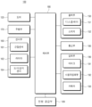
도 2는 본 발명의 일 실시 예에 따른 배송로봇의 구성을 설명하기 위한 블록도이다.
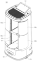
도 3은 본 발명의 일 실시 예에 따른 배송로봇의 전방 사시도이다.
도 4 및 도 5는 본 발명의 일 실시 예에 따른 배송로봇의 도어가 개방된 상태를 도시한 도면이다.
도 6은 본 발명의 일 실시예에 따른 배송로봇의 수납부 내부를 도시한 도면이다.
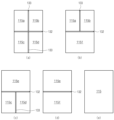
도 7은 본 발명의 일 실시예에 따른 배송로봇의 수납부의 구획 방법을 도시한 개념도이다.
도 8은 본 발명의 일 실시예에 따른 배송로봇의 도어 구동부를 도시한 평면도이다.
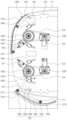
도 9는 본 발명의 일 실시 예에 따른 배송로봇의 도어 구동부를 도시한 사시도이다.
도 10은 본 발명의 일 실시 예에 따른 배송로봇의 링크의 동작을 설명하기 위한 개념도이다.
도 11은 본 발명의 일 실시 예에 따른 배송로봇의 도어 구동부를 하측에서 바라본 도면이다.
도 12는 본 발명의 일 실시예에 따른 배송로봇의 중간선반의 결합방법을 도시한 도면이다.
도 13은 본 발명의 일 실시예에 따른 배송로봇의 탄성센서를 도시한 분해도이다.
도 14는 본 발명의 일 실시예에 따른 배송로봇의 제1 탄성센서의 동작을 도시한 도면이다.
도 15는 본 발명의 일 실시예에 따른 배송로봇의 중간선반의 측면도와 저면도이다.
도 16는 본 발명의 일 실시예에 따른 배송로봇의 수납부의 파티션을 삽입하는 방법을 설명하기 위한 도면이다
도 17은 본 발명의 일 실시예에 따른 배송로봇의 수납부 내부를 도시한 단면도이다.
도 18은 본 발명의 일 실시예에 따른 배송로봇의 파티션 수납방법을 도시한 도면이다.
도 19 및 도 20는 본 발명의 일 실시예에 따른 배송로봇의 수납레일과 파티션을 도시한 도면이다.
도 21은 본 발명의 일 실시예에 따른 배송로봇의 파티션 수납방법의 다른 실시예를 도시한 도면이다.
도 22은 본 발명의 일 실시예에 따른 배송로봇의 슬라이딩 선반이 인출된 상태를 도시한 사시도이다.
도 23는 도 22 상태를 도시한 측면도이다.
도 24는 본 발명의 일 실시예에 따른 배송로봇의 슬라이딩 선반 및 선반 구동부를 도시한 분해 사시도이다.
도 25는 본 발명의 일 실시예에 따른 배송로봇의 수납부 베이스에 결합된 슬라이딩 레일 및 슬라이딩 선반을 도시한 도면이다.
도 26은 본 발명의 일 실시예에 따른 배송로봇의 슬라이딩 선반 분리방법을 도시한 도면이다.
도 27은 본 발명의 일 실시예에 따른 배송로봇의 슬라이딩 선반의 안전제어 방법에 관한 것이다.
도 28 및 도 29는 본 발명의 다른 실시예에 따른 배송로봇의 슬라이딩 선반(131)의 구동부를 도시한 도면이다.
도 30은 본 발명의 일 실시예에 따른 배송로봇의 수납부를 도시한 정면도이다.
도 31은 본 발명의 일 실시예에 따른 배송로봇의 파티션의 유무에 따라 상부 수납부에 위치하는 내부 카메라가 촬영한 화면을 도시한 도면이다.
도 32는 본 발명의 일 실시예에 따른 배송로봇의 내부 카메라(195)의 화각을 도시한 개념도이다.
도 33은 본 발명의 일 실시예에 따른 배송로봇의 내부 카메라(195)를 하측으로 20° 기울인 상태에서 촬영한 경우를 도시한 도면이다.
도 34는 본 발명의 일 실시예에 따른 배송로봇의 내부 카메라를 하측으로 30° 기울인 상태에서 촬영한 경우를 도시한 도면이다.
도 35는 호텔에서 고객이 호텔리어에게 물품을 요청한 경우 이를 배송로봇을 이용하여 고객에게 전달하는 과정을 나타낸 순서도이다.
도 36 및 도 37은 도 35의 시나리오를 배송로봇의 제어부의 제어로직을 도시한 순서도이다.FIG. 1 is a diagram illustrating a cloud system based on a 5G network according to one embodiment of the present invention.
FIG. 2 is a block diagram illustrating the configuration of a delivery robot according to one embodiment of the present invention.
FIG. 3 is a front perspective view of a delivery robot according to one embodiment of the present invention.
FIGS. 4 and 5 are drawings illustrating a state in which the door of a delivery robot is opened according to one embodiment of the present invention.
FIG. 6 is a drawing illustrating the inside of a storage unit of a delivery robot according to one embodiment of the present invention.
FIG. 7 is a conceptual diagram illustrating a method for partitioning a storage compartment of a delivery robot according to one embodiment of the present invention.
FIG. 8 is a plan view illustrating a door driving unit of a delivery robot according to one embodiment of the present invention.
FIG. 9 is a perspective view illustrating a door driving unit of a delivery robot according to an embodiment of the present invention.
FIG. 10 is a conceptual diagram for explaining the operation of a link of a delivery robot according to one embodiment of the present invention.
FIG. 11 is a drawing of a door drive unit of a delivery robot according to an embodiment of the present invention viewed from below.
FIG. 12 is a drawing illustrating a method for combining an intermediate shelf of a delivery robot according to one embodiment of the present invention.
FIG. 13 is an exploded view illustrating an elasticity sensor of a delivery robot according to one embodiment of the present invention.
FIG. 14 is a drawing illustrating the operation of a first elasticity sensor of a delivery robot according to one embodiment of the present invention.
FIG. 15 is a side view and a bottom view of an intermediate shelf of a delivery robot according to one embodiment of the present invention.
FIG. 16 is a drawing for explaining a method of inserting a partition into a storage compartment of a delivery robot according to one embodiment of the present invention.
Fig. 17 is a cross-sectional view illustrating the inside of a storage unit of a delivery robot according to one embodiment of the present invention.
FIG. 18 is a drawing illustrating a partition storage method of a delivery robot according to one embodiment of the present invention.
FIGS. 19 and 20 are drawings illustrating a storage rail and partition of a delivery robot according to one embodiment of the present invention.
FIG. 21 is a drawing illustrating another embodiment of a partition storage method of a delivery robot according to one embodiment of the present invention.
FIG. 22 is a perspective view showing a state in which a sliding shelf of a delivery robot according to one embodiment of the present invention is withdrawn.
Figure 23 is a side view showing the state of Figure 22.
FIG. 24 is an exploded perspective view illustrating a sliding shelf and shelf drive unit of a delivery robot according to one embodiment of the present invention.
FIG. 25 is a drawing illustrating a sliding rail and a sliding shelf coupled to a storage unit base of a delivery robot according to one embodiment of the present invention.
FIG. 26 is a drawing illustrating a sliding shelf separation method of a delivery robot according to one embodiment of the present invention.
FIG. 27 relates to a safety control method of a sliding shelf of a delivery robot according to one embodiment of the present invention.
FIG. 28 and FIG. 29 are drawings illustrating a driving unit of a sliding shelf (131) of a delivery robot according to another embodiment of the present invention.
Figure 30 is a front view illustrating a storage unit of a delivery robot according to one embodiment of the present invention.
FIG. 31 is a drawing showing a screen captured by an internal camera located in an upper storage section depending on the presence or absence of a partition in a delivery robot according to one embodiment of the present invention.
Figure 32 is a conceptual diagram illustrating the angle of view of an internal camera (195) of a delivery robot according to one embodiment of the present invention.
FIG. 33 is a drawing illustrating a case where the internal camera (195) of a delivery robot according to one embodiment of the present invention is photographed while tilted downward at 20°.
FIG. 34 is a drawing illustrating a case where the internal camera of a delivery robot according to one embodiment of the present invention is taken while tilted downward at 30°.
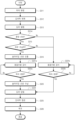
Figure 35 is a flowchart showing the process of delivering items to customers using a delivery robot when a customer requests items from a hotelier.
Figures 36 and 37 are flowcharts illustrating the control logic of the control unit of the delivery robot in the scenario of Figure 35.
이하, 첨부된 도면을 참조하여 본 명세서에 개시된 실시 예를 상세히 설명하되, 도면 부호에 관계없이 동일하거나 유사한 구성요소는 동일한 참조 번호를 부여하고 이에 대한 중복되는 설명은 생략하기로 한다. 이하의 설명에서 사용되는 구성요소에 대한 접미사 "모듈" 및 "부"는 명세서 작성의 용이함만이 고려되어 부여되거나 혼용되는 것으로서, 그 자체로 서로 구별되는 의미 또는 역할을 갖는 것은 아니다. 또한, 본 명세서에 개시된 실시 예를 설명함에 있어서 관련된 공지 기술에 대한 구체적인 설명이 본 명세서에 개시된 실시 예의 요지를 흐릴 수 있다고 판단되는 경우 그 상세한 설명을 생략한다. 또한, 첨부된 도면은 본 명세서에 개시된 실시 예를 쉽게 이해할 수 있도록 하기 위한 것일 뿐, 첨부된 도면에 의해 본 명세서에 개시된 기술적 사상이 제한되지 않으며, 본 발명의 사상 및 기술 범위에 포함되는 모든 변경, 균등물 내지 대체물을 포함하는 것으로 이해되어야 한다. Hereinafter, embodiments disclosed in this specification will be described in detail with reference to the attached drawings. Regardless of the drawing symbols, identical or similar components will be given the same reference numerals and redundant descriptions thereof will be omitted. The suffixes "module" and "part" used for components in the following description are assigned or used interchangeably only for the convenience of writing the specification, and do not have distinct meanings or roles in themselves. In addition, when describing embodiments disclosed in this specification, if it is determined that a specific description of a related known technology may obscure the gist of the embodiments disclosed in this specification, the detailed description thereof will be omitted. In addition, the attached drawings are only intended to facilitate easy understanding of the embodiments disclosed in this specification, and the technical ideas disclosed in this specification are not limited by the attached drawings, and should be understood to include all modifications, equivalents, and substitutes included in the spirit and technical scope of the present invention.
제1, 제2 등과 같이 서수를 포함하는 용어는 다양한 구성요소들을 설명하는데 사용될 수 있지만, 상기 구성요소들은 상기 용어들에 의해 한정되지는 않는다. 상기 용어들은 하나의 구성요소를 다른 구성요소로부터 구별하는 목적으로만 사용된다.Terms that include ordinal numbers, such as first, second, etc., may be used to describe various components, but the components are not limited by the terms. The terms are used only to distinguish one component from another.
어떤 구성요소가 다른 구성요소에 "연결되어" 있다거나 "접속되어" 있다고 언급된 때에는, 그 다른 구성요소에 직접적으로 연결되어 있거나 또는 접속되어 있을 수도 있지만, 중간에 다른 구성요소가 존재할 수도 있다고 이해되어야 할 것이다. 반면에, 어떤 구성요소가 다른 구성요소에 "직접 연결되어" 있다거나 "직접 접속되어" 있다고 언급된 때에는, 중간에 다른 구성요소가 존재하지 않는 것으로 이해되어야 할 것이다.When it is said that a component is "connected" or "connected" to another component, it should be understood that it may be directly connected or connected to that other component, but that there may be other components in between. On the other hand, when it is said that a component is "directly connected" or "directly connected" to another component, it should be understood that there are no other components in between.
단수의 표현은 문맥상 명백하게 다르게 뜻하지 않는 한, 복수의 표현을 포함한다. Singular expressions include plural expressions unless the context clearly indicates otherwise.
본 출원에서, "포함한다" 또는 "가지다" 등의 용어는 명세서상에 기재된 특징, 숫자, 단계, 동작, 구성요소, 부품 또는 이들을 조합한 것이 존재함을 지정하려는 것이지, 하나 또는 그 이상의 다른 특징들이나 숫자, 단계, 동작, 구성요소, 부품 또는 이들을 조합한 것들의 존재 또는 부가 가능성을 미리 배제하지 않는 것으로 이해되어야 한다.In this application, it should be understood that terms such as “comprises” or “has” are intended to specify the presence of a feature, number, step, operation, component, part or combination thereof described in the specification, but do not exclude in advance the possibility of the presence or addition of one or more other features, numbers, steps, operations, components, parts or combinations thereof.
로봇은 어떤 작업이나 조작을 자동으로 할 수 있는 기계 장치로서, 로봇은 외부의 제어 장치에 의해 조종되거나 제어 장치가 내장될 수도 있다. 기 설정된 동작만 반복하여 처리하거나 무거운 물건을 들어올리거나, 정밀한 작업의 수행 및 극한의 환경에서의 작업과 같이 인간이 수행하기 어려운 작업을 수행할 수 있다. A robot is a mechanical device that can automatically perform certain tasks or operations. The robot may be controlled by an external control device or may have a built-in control device. It can perform tasks that are difficult for humans to perform, such as repeating preset movements, lifting heavy objects, performing precision work, and working in extreme environments.
작업수행을 위해 액츄에이터 또는 모터를 포함하는 구동부를 구비하여 로봇 관절을 움직이는 등의 다양한 물리적 동작을 수행할 수 있다.A driving unit including an actuator or motor can be provided to perform various physical actions, such as moving the robot joints, to perform tasks.
로봇은 그 제조비용이 높고 조작의 전문성 등의 문제로 특정 작업에 특화된 외관을 가지는 산업용 로봇이나 의료용 로봇이 먼저 발달 되었다. 산업용, 의료용 로봇은 지정된 장소에서 동일한 동작을 반복수행하나, Robots are developed first as industrial robots or medical robots with specialized appearances for specific tasks due to high manufacturing costs and issues such as specialized operation. Industrial and medical robots perform the same movements repeatedly in a designated location, but
최근에는 이동 가능한 로봇이 등장하고 있다. 특히 우주항공산업과 같이 인간이 직접 가기 어려운 먼 행성에서 탐사작업 등을 수행할 수 있으며 이러한 로봇은 주행기능이 추가된다. Recently, mobile robots have been introduced. In particular, they can perform exploration work on distant planets where humans cannot go directly, such as in the aerospace industry, and these robots have additional driving functions.
주행기능을 수행하기 위해서는 구동부를 구비하며 휠, 브레이트, 캐스터, 모터 등을 포함할 수 있으며 주변의 장애물을 파악하고 이를 피해 주행하기 위해서는 인공지능을 탑재한 로봇이 등장하고 있다. In order to perform the driving function, a driving unit is required and may include wheels, brakes, casters, motors, etc., and robots equipped with artificial intelligence are appearing to identify obstacles in the surroundings and drive to avoid them.
인공지능 기술이 적용되어, 안내 로봇, 운반 로봇, 청소 로봇, 웨어러블 로봇, 엔터테인먼트 로봇, 펫 로봇, 무인 비행 로봇 등으로 구현될 수 있다.By applying artificial intelligence technology, it can be implemented as guide robots, transport robots, cleaning robots, wearable robots, entertainment robots, pet robots, and unmanned flying robots.
로봇은 동작을 제어하기 위한 로봇 제어 모듈을 포함할 수 있고, 로봇 제어 모듈은 소프트웨어 모듈 또는 이를 하드웨어로 구현한 칩을 의미할 수 있다.The robot may include a robot control module for controlling movements, and the robot control module may mean a software module or a chip implementing the same as hardware.
로봇은 다양한 종류의 센서들로부터 획득한 센서 정보를 이용하여 로봇의 상태 정보를 획득하거나, 주변 환경 및 객체를 검출(인식)하거나, 맵 데이터를 생성하거나, 이동 경로 및 주행 계획을 결정하거나, 사용자 상호작용에 대한 응답을 결정하거나, 동작을 결정할 수 있다.Robots can use sensor information acquired from various types of sensors to acquire robot status information, detect (recognize) the surrounding environment and objects, generate map data, determine movement paths and driving plans, determine responses to user interactions, or determine actions.
로봇은 적어도 하나 이상의 인공 신경망으로 구성된 학습 모델을 이용하여 상기한 동작들을 수행할 수 있다. 예컨대, 로봇은 학습 모델을 이용하여 주변 환경 및 객체를 인식할 수 있고, 인식된 주변 환경 정보 또는 객체 정보를 이용하여 동작을 결정할 수 있다. 여기서, 학습 모델은 로봇에서 직접 학습되거나, AI 서버등의 외부 장치에서 학습된 것일 수 있다.The robot can perform the above-described actions using a learning model composed of at least one artificial neural network. For example, the robot can recognize the surrounding environment and objects using the learning model, and determine actions using the recognized surrounding environment information or object information. Here, the learning model can be learned directly by the robot or learned from an external device such as an AI server.
이때, 로봇은 직접 학습 모델을 이용하여 결과를 생성하여 동작을 수행할수도 있지만, AI 서버 등의 외부 장치에 센서 정보를 전송하고 그에 따라 생성된 결과를 수신하여 동작을 수행할 수도 있다.At this time, the robot can perform actions by generating results using a direct learning model, but it can also transmit sensor information to an external device such as an AI server and perform actions by receiving the results generated accordingly.
인공 지능을 통해 로봇은 자율주행을 수행할 수 있다. 스스로 최적의 경로를 판단하고 장애물을 피해서 이동 가능한 기술을 의미하며 현재 적용되고 있는 자율주행 기술은 주행중인 차선을 유지하는 기술, 어댑티브 크루즈 컨트롤과 같이 속도를 자동으로 조절하는 기술, 정해진 경로를 따라 자동으로 주행하는 기술, 목적지가 설정되면 자동으로 경로를 설정해주는 주행기술 등이 모두 포함될 수 있다. Through artificial intelligence, robots can perform autonomous driving. This refers to technology that can determine the optimal path on its own and move while avoiding obstacles. Currently applied autonomous driving technology can include technology that maintains the driving lane, technology that automatically adjusts speed such as adaptive cruise control, technology that automatically drives along a set path, and driving technology that automatically sets a path when a destination is set.
자율주행을 수행하기 위해서는 주변상황의 데이터를 인지하기 위해 수많은 센서를 포함할 수 있다. 센서로는 근접 센서, 조도 센서, 가속도 센서, 자기센서, 자이로 센서, 관성 센서, RGB 센서, IR 센서, 지문 인식 센서, 초음파 센서, 광 센서, 마이크로폰, 라이다, 레이더 등을 들 수 있다. In order to perform autonomous driving, numerous sensors may be included to recognize data from the surroundings. Sensors include proximity sensors, light sensors, acceleration sensors, magnetic sensors, gyro sensors, inertial sensors, RGB sensors, IR sensors, fingerprint recognition sensors, ultrasonic sensors, light sensors, microphones, lidar, radar, etc.
센서에서 수집한 정보 이외에 RGBC카메라, 적외선 카메라 등을 통해 수집한 영상정보와 마이크로폰을 통해 수집한 음향정보를 통해 자율주행을 수행할 수 있다. 또한, 사용자 입력부를 통해 입력된 정보에 기초하여 주행할 수 있다. 무선통신부를 통해 수집한 맵 데이터, 위치정보 및 주변 상황의 정보 등 또한 자율주행 수행에 필요한 정보들이다. In addition to the information collected from the sensor, autonomous driving can be performed using image information collected through RGBC cameras, infrared cameras, etc., and audio information collected through microphones. In addition, driving can be performed based on information entered through the user input section. Map data, location information, and information on the surrounding situation collected through the wireless communication section are also necessary information for autonomous driving.
맵 데이터에는 로봇이 이동하는 공간에 배치된 다양한 객체들에 대한 객체 식별 정보가 포함될 수 있다. 예컨대, 맵 데이터에는 벽, 문 등의 고정 객체들과 화분, 책상 등의 이동 가능한 객체들에 대한 객체 식별 정보가 포함될 수 있다. 그리고, 객체 식별 정보에는 명칭, 종류, 거리, 위치 등이 포함될 수 있다.Map data may include object identification information for various objects placed in the space where the robot moves. For example, map data may include object identification information for fixed objects such as walls and doors, and movable objects such as flower pots and desks. In addition, object identification information may include name, type, distance, location, etc.
따라서 로봇은 인공지능이 학습할 수 있는 데이터를 수집하기 위해 센서 및 다양한 입력부 그리고 무선통신부 등을 필수적으로 구비하고 각종정보를 종합하여 최적의 동작을 수행할 수 있다. 인공지능을 수행하는 러닝 프로세서는 로봇내의 제어부에 탑재하여 학습을 수행할 수도 있고, 수집한 정보를 서보로 전송하고 서버를 통해 학습하여 학습결과를 로봇에 다시 전송하여 이를 기초로 자율주행을 수행할 수 있다. Therefore, the robot is equipped with sensors, various input units, and wireless communication units to collect data that AI can learn from, and can perform optimal operations by synthesizing various information. The learning processor that performs AI can be installed in the control unit within the robot to perform learning, or the collected information can be transmitted to the servo, learned through the server, and the learning results can be sent back to the robot to perform autonomous driving based on this.
인공지능을 구비한 로보트는 새로운 장소에서도 주변 정보를 수집하여 전체 맵을 구현할 수 있으며, 주요활동반경의 장소는 누적되는 정보량이 많아 보다 정확한 자율주행을 수행할 수 있다. Robots equipped with artificial intelligence can collect information about their surroundings even in new locations and create a full map, and can perform more accurate autonomous driving in places with a large accumulated amount of information in the main activity radius.
사용자 입력을 받기위해 터치스크린이나 버튼을 구비할 수 있으며 사용자의 음성을 인식하여 명령을 입력받을 수도 있다. 프로세서는 음성입력을 문자열로 변환하기 위해 STT(Speech To Text) 엔진 또는 자연어의 의도 정보를 획득하기 위한 자연어 처리(NLP: Natural Language Processing) 엔진 중에서 적어도 하나 이상을 이용하여, 사용자 입력에 상응하는 의도 정보를 획득할 수 있다.A touch screen or buttons may be provided to receive user input, and commands may be received by recognizing the user's voice. The processor may use at least one of an STT (Speech To Text) engine to convert voice input into a string, or a natural language processing (NLP) engine to obtain intention information of natural language, to obtain intention information corresponding to the user input.
이때, STT 엔진 또는 NLP 엔진 중에서 적어도 하나 이상은 적어도 일부가 머신 러닝 알고리즘에 따라 학습된 인공 신경망으로 구성될 수 있다. 그리고, STT 엔진 또는 NLP 엔진 중에서 적어도 하나 이상은 러닝 프로세서에 의해 학습된 것이나, AI 서버의 러닝 프로세서에 의해 학습된 것이거나, 또는 이들의 분산 처리에 의해 학습된 것일 수 있다.At this time, at least one of the STT engine or the NLP engine may be configured with an artificial neural network at least partially learned according to a machine learning algorithm. And, at least one of the STT engine or the NLP engine may be learned by a learning processor, by a learning processor of an AI server, or by distributed processing thereof.
도 1은 본 발명의 일 실시 예에 따른 5G 네트워크 기반의 클라우드 시스템(1000)을 나타낸다.FIG. 1 illustrates a cloud system (1000) based on a 5G network according to one embodiment of the present invention.
도 1을 참고하면, 클라우드 시스템(1000)은 배송로봇(100), 이동 단말(300), 로봇 관제 시스템(200), 각종 기기(400) 및 5G 네트워크(500)를 포함할 수 있다. 배송로봇(100)은 물품을 출발지에서 목적지로 운반하는 로봇이다. Referring to FIG. 1, a cloud system (1000) may include a delivery robot (100), a mobile terminal (300), a robot control system (200), various devices (400), and a 5G network (500). The delivery robot (100) is a robot that transports goods from a departure point to a destination.
배송로봇(100)은 실외뿐만 아니라 실내에서도 물품을 목적지로 이동할 수 있다. 배송로봇(100)은 AGV(Automated Guided Vehicle)로 구현될 수 있으며, AGV는 바닥면의 센서, 자기장, 비전기기 등에 의해 움직이는 운송 장치일 수 있다.The delivery robot (100) can move goods to their destination not only outdoors but also indoors. The delivery robot (100) can be implemented as an AGV (Automated Guided Vehicle), and the AGV can be a transport device that moves by sensors, magnetic fields, vision devices, etc. on the floor.
배송로봇(100)은 물품을 수납할 수 있도록 선반을 구비하며 측벽이 생략되어 내부가 개방된 타입 또는 주행거리가 긴 경우 도어로 개폐가능한 수납부를 포함하는 형태로 구성할 수 있다. The delivery robot (100) is equipped with shelves for storing items, and can be configured as a type with an open interior with the side walls omitted, or a type that includes a storage section that can be opened and closed with a door in case of a long travel distance.
이동 단말(300)은 5G 네트워크(500)를 통해 배송로봇(100)과 통신할 수 있다. 이동 단말(300)은 물품을 적재하기 위해 파티션을 보관 영역에 설치하는 사용자가 소지한 기기 또는 적재된 물품의 수령자가 소지한 기기일 수 있다. 이동 단말(300)은 영상 기반으로 정보를 제공할 수 있으며, 이동 단말(300)은 휴대폰, 스마트 폰(smart phone), 웨어러블 디바이스(wearable device, 예를 들어, 워치형 단말기 (smartwatch), 글래스형 단말기 (smart glass), HMD(head mounted display)) 등의 이동형 기기들을 포함할 수 있다.The mobile terminal (300) can communicate with the delivery robot (100) via the 5G network (500). The mobile terminal (300) can be a device carried by a user who installs a partition in a storage area to load goods, or a device carried by a recipient of loaded goods. The mobile terminal (300) can provide information based on images, and the mobile terminal (300) can include mobile devices such as a mobile phone, a smart phone, a wearable device (e.g., a smartwatch, a smart glass, a head mounted display (HMD)).
로봇 관제 시스템(200)는 배송로봇(100)을 원격으로 제어할 수 있으며, 배송로봇(100)의 다양한 요청에 응답할 수 있다. 예를 들면, 로봇 관제 시스템(200)은 배송로봇(100)의 요청에 기초하여, 인공 지능을 이용한 연산을 수행할 수 있다.The robot control system (200) can remotely control the delivery robot (100) and respond to various requests from the delivery robot (100). For example, the robot control system (200) can perform calculations using artificial intelligence based on requests from the delivery robot (100).
또한, 로봇 관제 시스템(200)은 배송로봇(100)의 이동 경로를 설정할 수 있으며, 로봇 관제 시스템(200)은 복수의 목적지가 있는 경우, 목적지의 이동 순서를 설정할 수 있다.In addition, the robot control system (200) can set the movement path of the delivery robot (100), and, if there are multiple destinations, the robot control system (200) can set the movement order of the destinations.
각종 기기(400)는 개인 컴퓨터(PC, 400a), 자율 주행차(400b), 홈 로봇(400c) 등을 포함할 수 있다. 배송로봇(100)은 물품의 운송 목적지에 도착하는 경우, 홈 로봇(400c)과의 통신을 통해 홈 로봇(400c)에 직접 물품을 전달할 수 있다.The various devices (400) may include a personal computer (PC, 400a), an autonomous vehicle (400b), a home robot (400c), etc. When the delivery robot (100) arrives at the transport destination of the goods, it can directly deliver the goods to the home robot (400c) through communication with the home robot (400c).
각종 기기(400)는 배송로봇(100), 이동 단말(300), 로봇 관제 시스템(200) 등과 5G 네트워크(500)를 통해 유무선으로 연결될 수 있다.Various devices (400) can be connected wirelessly or wiredly to a delivery robot (100), a mobile terminal (300), a robot control system (200), etc. through a 5G network (500).
상기 배송로봇(100), 이동 단말(300), 로봇 관제 시스템(200) 및 각종 기기(400)는 모두 5G 모듈을 탑재하여 100Mbps 내지 20Gbps(또는, 그 이상) 속도로 데이터를 송수신할 수 있어서 대용량의 동영상 파일을 다양한 기기로 전송할 수 있으며, 저전력으로 구동되어 전력 소비가 최소화되게 할 수 있다. 다만, 상기 전송 속도는 실시 예에 따라 달리 구현될 수 있다.The above delivery robot (100), mobile terminal (300), robot control system (200), and various devices (400) are all equipped with 5G modules to transmit and receive data at a speed of 100 Mbps to 20 Gbps (or higher), so that large-capacity video files can be transmitted to various devices, and power consumption can be minimized by operating at low power. However, the transmission speed may be implemented differently depending on the embodiment.
5G 네트워크(500)는 5G 이동 통신 네트워크, 근거리 네트워크, 인터넷 등을 포함할 수 있으며, 유무선으로 기기들의 통신 환경을 제공할 수 있다.The 5G network (500) may include a 5G mobile communication network, a short-range network, the Internet, etc., and may provide a communication environment for devices with or without wires.
도 2은 본 발명의 일 실시 예에 따른 배송로봇(100)의 구성을 설명하기 위한 블럭도이며, 도 3은 본 발명의 일 실시 예에 따른 배송로봇(100)의 전방 사시도이다. 도 2에 도시된 구성요소들은 배송로봇(100)을 구현하는데 있어서 필수적인 것은 아니어서, 본 명세서 상에서 설명되는 배송로봇(100)은 위에서 열거된 구성요소들 보다 많거나, 또는 적은 구성요소들을 가질 수 있다.FIG. 2 is a block diagram for explaining the configuration of a delivery robot (100) according to an embodiment of the present invention, and FIG. 3 is a front perspective view of a delivery robot (100) according to an embodiment of the present invention. The components illustrated in FIG. 2 are not essential for implementing the delivery robot (100), and thus, the delivery robot (100) described in this specification may have more or fewer components than the components listed above.
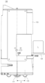
도 3을 참고하면, 배송로봇(100)의 바디(110)는 내부에 각종 부품이 실장되고 물품을 수납할 수 있는 수납부를 포함한다. 바디(110)는 하부에 위치하는 주행부(170)를 통해 이동할 수 있다. 비다는 외관을 구성하는 바디 하우징(111), 바디 하우징(110) 내에 물품을 수납할 수 있는 선반을 포함하는 수납부(115, 도 4 참조)를 포함할 수 있다. Referring to FIG. 3, the body (110) of the delivery robot (100) includes a storage section in which various parts are mounted inside and items can be stored. The body (110) can move through a driving section (170) located at the bottom. The robot may include a body housing (111) that forms an exterior, and a storage section (115, see FIG. 4) that includes a shelf that can store items inside the body housing (110).
도 2를 참조하면 본 발명의 배송로봇(100)은 도어(120), 주행부(170), 센서부(160), 출력부(150), 입력부(190), 제어부(180), 통신부(185) 및 전원 공급부(189)를 포함할 수 있다. Referring to FIG. 2, the delivery robot (100) of the present invention may include a door (120), a driving unit (170), a sensor unit (160), an output unit (150), an input unit (190), a control unit (180), a communication unit (185), and a power supply unit (189).
도어(120는 바디(110)의 일측에 형성된 바디(110) 개구부를 개폐하여, 수납부 내부를 선택적으로 개방할 수 있다. 주행 시 주행방향을 감지하기 위해 바디 하우징(111)은 노출된 카메라(193), 라이다(162) 및 근접센서(161) 등이 주행 방향을 향하도록 위치할 수 있다. 물품을 인입출하는 바디(110) 개구부는 주 주행방향의 반대방향에 위치할 수 있다. The door (120) can selectively open the inside of the storage compartment by opening and closing the body (110) opening formed on one side of the body (110). In order to detect the driving direction during driving, the body housing (111) can be positioned so that the exposed camera (193), lidar (162), and proximity sensor (161) face the driving direction. The body (110) opening for inserting and removing items can be positioned in the opposite direction to the main driving direction.
본 발명에서는 바디(110) 내부의 수납부(115)를 개폐하여 물품을 수납 및 수령하는 것에 특징이 있는 바, 도어(120)가 있는 방향을 전방으로 설명하고 그 반대편, 즉 주행방향을 후방이라 한다. The present invention is characterized by opening and closing the storage section (115) inside the body (110) to store and receive items. The direction in which the door (120) is located is described as the front, and the opposite direction, i.e. the driving direction, is described as the rear.
도어(120)는 여닫이 형태로 구동 시 배송로봇(100)의 전방에 충분한 공간이 확보되어야 하므로, 제한된 공간에서 개폐 가능하도록 슬라이드 타입으로 구동될 수 있다. 다만, 배송로봇(100)은 도 3에 도시된 바와 같이 원통형의 바디(110)를 가지며 물품의 원활한 인입출을 위해 전방의 대부분의 면적을 도어(120)로 커버된 바디(110) 개구부로 할애하고 있다. Since the door (120) must secure sufficient space in front of the delivery robot (100) when operated in an openable manner, it may be operated in a slide type so that it can be opened and closed in a limited space. However, as shown in Fig. 3, the delivery robot (100) has a cylindrical body (110) and most of the front area is devoted to the opening of the body (110) covered by the door (120) for smooth entry and exit of goods.
수납부를 노출시키는 바디(110)의 개구부는 바디(110)의 전면을 모두 차지한다. 도어(120)가 바디의 전면과 평행한 방향으로 슬라이드 이동하는 경우 바디(110)의 좌우 방향으로 공간이 확보되어야 한다. The opening of the body (110) exposing the storage compartment occupies the entire front of the body (110). When the door (120) slides in a direction parallel to the front of the body, space must be secured in the left and right directions of the body (110).
따라서 본 발명의 배송로봇(100)의 도어(120)는 바디(110)의 외측면에서 최대한 이격되지 않는 궤도를 이루며 회전하여 개방되도록 도어 구동부를 구성할 수 있다. Accordingly, the door (120) of the delivery robot (100) of the present invention can be configured to have a door drive unit that rotates and opens in a track that is as close as possible to the outer surface of the body (110).
도어(120)는 바디(110)의 외측면 일부를 구성하는 도어패널(121)을 포함하며, 도어패널(121)을 구동하기 위해 모터(122) 및 링크(128, 129) 등을 포함할 수 있다. The door (120) includes a door panel (121) that constitutes a portion of the outer surface of the body (110), and may include a motor (122) and links (128, 129), etc., to drive the door panel (121).
도 3에 도시된 바와 같이 도어패널(121a, 121b, 121c, 121d)은 복수 개를 구비할 수 있으며, 복수 개의 도어패널(121a, 121b, 121c, 121d)은 독립적으로 구동할 수 있다. 복수개의 도어패널(121a, 121b, 121c, 121d)은 바디 하우징(111) 내부의 수납부 구성에 따라 동시에 또는 개별적으로 구동할 수 있다. As illustrated in FIG. 3, a plurality of door panels (121a, 121b, 121c, 121d) may be provided, and the plurality of door panels (121a, 121b, 121c, 121d) may be driven independently. The plurality of door panels (121a, 121b, 121c, 121d) may be driven simultaneously or individually depending on the configuration of the storage compartment inside the body housing (111).
출력부(150)는 시각, 청각 또는 촉각 등과 관련된 출력을 발생시킬 수 있는데, 출력부(150)는 시각 정보를 출력하는 광 출력부, 디스플레이 (151) 등을 포함할 수 있으며, 청각 정보를 출력하는 스피커 (152), 비가청 주파수에 속하는 초음파 신호를 출력하는 초음파 출력부 등을 포함할 수 있고, 촉각 정보를 출력하는 햅틱 모듈을 포함할 수 있다.The output unit (150) can generate output related to vision, hearing, or tactile sensations, and the output unit (150) can include an optical output unit that outputs visual information, a display (151), etc., a speaker (152) that outputs auditory information, an ultrasonic output unit that outputs ultrasonic signals belonging to an inaudible frequency, etc., and can include a haptic module that outputs tactile information.
센서부(160)는 다양한 센서들을 이용하여 배송로봇(100)의 내부 정보, 배송로봇(100)의 주변 환경 정보 및 사용자 정보 중 적어도 하나를 획득할 수 있다.The sensor unit (160) can obtain at least one of internal information of the delivery robot (100), information about the surrounding environment of the delivery robot (100), and user information using various sensors.
이때, 센서부(160)는 자율주행을 위해 주변을 인식하기 위한 다양한 종류의 센서를 포함할 수 있다. 대표적으로 거리 감지 센서 또는 근접센서(161)와 라이다(162)를 들 수 있다.At this time, the sensor unit (160) may include various types of sensors for recognizing the surroundings for autonomous driving. Representative examples include a distance detection sensor or proximity sensor (161) and a lidar (162).
근접센서(161)는 사출한 초음파가 돌아오는 시간을 기초로 근처의 사물을 인식하고 사물과의 거리를 판단하는 초음파 센서를 포함할 수 있다. 근접센서는 둘레를 따라 복수개를 구비할 수 있으며, 상측의 장애물을 감지하기 위해 상측에도 구비할 수 있다. The proximity sensor (161) may include an ultrasonic sensor that recognizes nearby objects and determines the distance to the objects based on the time it takes for the emitted ultrasonic waves to return. A plurality of proximity sensors may be provided along the perimeter, and one may also be provided on the upper side to detect obstacles on the upper side.
라이다(Lidar, 162)는 레이저 펄스를 발사하고 그 빛이 주위의 대상물체에 반사되어 돌아오는 것을 받아 주변의 모습을 정밀하게 그려내는 장치이다. 레이다와 같이 그 원리는 유사하나 사용하는 전자기파가 달라 이용 기술과 활용범위가 상이하다.Lidar (162) is a device that precisely draws the surroundings by firing laser pulses and receiving the light that is reflected from surrounding objects. Its principle is similar to radar, but the electromagnetic waves used are different, so the technology and scope of use are different.
레이저는 600~1000nm 파장의 빛을 사용하기 때문에 사람의 시력을 손상시킬 수 있다. 라이다(162)는 이보다 더 긴 파장을 이용하며, 대상 물체까지의 거리뿐 아니라 움직이는 속도와 방향, 온도, 주변의 대기 물질 분석 및 농도 측정 등에 쓰인다.Lasers can damage human eyesight because they use light with a wavelength of 600 to 1000 nm. Lidar (162) uses a longer wavelength and is used to measure not only the distance to a target object, but also the speed and direction of its movement, temperature, and analysis and concentration of surrounding atmospheric substances.
그 외에 센서부(160)는 조도 센서, 가속도 센서, 자기 센서, 자이로 센서, 관성 센서, RGB 센서, 적외선 센서, 지문 인식 센서, 초음파 센서, 광 센서, 홀센서 등을 포함할 수 있다. In addition, the sensor unit (160) may include a light sensor, an acceleration sensor, a magnetic sensor, a gyro sensor, an inertial sensor, an RGB sensor, an infrared sensor, a fingerprint recognition sensor, an ultrasonic sensor, a light sensor, a Hall sensor, etc.
주행부(170)는 배송로봇(100)을 이동시키기 위한 수단으로서, 휠 또는 레그를 포함할 수 있으며 이를 제어하는 휠 구동부 및 레그 구동부를 포함할 수 있다. The driving unit (170) is a means for moving the delivery robot (100), and may include wheels or legs, and may include a wheel driving unit and a leg driving unit for controlling the wheels or legs.
휠은 빠른 주행을 위한 메인휠(171, 도 14 참조)과 방향전환을 위한 캐스터(173) 그리고 주행 중 적재된 물품(L)이 떨어지지 않도록 안정적인 주행을 위한 보조 캐스터 등을 포함할 수 있다. The wheels may include a main wheel (171, see Fig. 14) for fast driving, a caster (173) for changing direction, and an auxiliary caster for stable driving to prevent loaded items (L) from falling during driving.
통신부(185, Transceiver)는 로봇 관제 시스템(200)과 통신할 수 있는 유무선의 통신 모듈을 포함할 수 있다.The communication unit (185, Transceiver) may include a wired or wireless communication module capable of communicating with the robot control system (200).
선택적 실시 예로 상기 통신부(185)는 GSM(Global System for Mobile communication), CDMA(Code Division Multi Access), LTE(Long Term Evolution), 5G, WLAN(Wireless LAN), Wi-Fi(Wireless-Fidelity), 블루투스(Bluetooth), RFID(Radio Frequency Identification), 적외선 통신(Infrared Data Association;IrDA), ZigBee, NFC(Near Field Communication) 통신에 관한 모듈을 탑재할 수 있다.As an optional embodiment, the communication unit (185) may be equipped with modules related to GSM (Global System for Mobile communication), CDMA (Code Division Multi Access), LTE (Long Term Evolution), 5G, WLAN (Wireless LAN), Wi-Fi (Wireless-Fidelity), Bluetooth, RFID (Radio Frequency Identification), Infrared Data Association (IrDA), ZigBee, and NFC (Near Field Communication) communications.
입력부(190)는 사용자로부터 정보를 입력 받기 위한 사용자 입력부(122)를 포함할 수 있다. 선택적 실시 예로 입력부(190)는 영상 신호 입력을 위한 카메라(193), 오디오 신호를 수신하기 위한 마이크로폰(123, "이하, 마이크로 칭함")을 포함할 수 있다. 여기서, 카메라(193)나 마이크(123)를 센서로 취급하여, 카메라(193)나 마이크(123)에서 획득한 신호를 센싱 데이터 또는 센서 정보라고 할 수도 있다.The input unit (190) may include a user input unit (122) for receiving information from a user. As an optional embodiment, the input unit (190) may include a camera (193) for inputting a video signal and a microphone (123, “hereinafter, referred to as a microphone”) for receiving an audio signal. Here, the camera (193) or the microphone (123) may be treated as a sensor, and a signal obtained from the camera (193) or the microphone (123) may be referred to as sensing data or sensor information.
카메라(193)는 주행방향의 장애물을 감지 하며, 도 3에 도시된 바와 같이 각도가 상이하게 복수 개가 배치될 수 있다. 전방을 넓게 인식하는 카메라와 바닥을 촬영하는 카메라와 같이 촬영 방향이 상이한 복수개의 카메라(193)를 구비할 수 있다. The camera (193) detects obstacles in the driving direction, and may be positioned at different angles as shown in Fig. 3. A plurality of cameras (193) with different shooting directions, such as a camera that widely recognizes the front and a camera that photographs the floor, may be provided.
수납부(115) 내부에 물품의 유무를 감지하기 위해 내부 카메라(195, 도 17 참조)를 더 포함할 수 있다. 내부 카메라(195)는 수납부(115)가 구획되는 경우 구획된 각 수납부(115a, 115b, 115c, 115d)를 모두 감지하기 위해 복수 개를 포함할 수 있다. An internal camera (195, see FIG. 17) may be further included to detect the presence or absence of an item inside the storage section (115). In the case where the storage section (115) is divided, a plurality of internal cameras (195) may be included to detect each of the divided storage sections (115a, 115b, 115c, 115d).
또는 상이한 기능을 가지는 카메라를 구비할 수 있다. 예를 들어 광각카메라, 적외선 카메라 등을 구비할 수 있다. 카메라는 센서부(160)로서 주변의 사물을 감지하는 역할을 할 수 있다. Or, it may be equipped with a camera having different functions. For example, it may be equipped with a wide-angle camera, an infrared camera, etc. The camera may serve as a sensor unit (160) to detect surrounding objects.
사용자 입력부(192)는 버튼이나 디스플레이(171)와 중첩된 터치패널을 구비할 수 있다. 또는 원격으로 통신부(185)를 통해 사용자 명령을 입력할 수도 있으며, 이 경우 사용자 입력부(192)는 배송로봇(100)과 별도로 구비된 개인 컴퓨터(400)나 원격제어장치를 포함할 수 있다. The user input unit (192) may be equipped with a button or a touch panel overlapping the display (171). Alternatively, a user command may be input remotely through a communication unit (185). In this case, the user input unit (192) may include a personal computer (400) or remote control device separately equipped from the delivery robot (100).
사용자 입력부(192)는 사용자 명령을 입력받는 방식을 모두 포함하므로 음성인식을 통해 사용자 명령을 인식할 수 있다. 즉 마이크(173)서 수집한 음성을 분석하여 사용자 명령을 추출하는 음성인식장치도 사용자 입력부(122)로서 역할을 할 수 있다. The user input unit (192) includes all methods for receiving user commands, so that user commands can be recognized through voice recognition. In other words, a voice recognition device that analyzes voice collected from a microphone (173) and extracts user commands can also function as the user input unit (122).
입력부(190)는 물품 정보 입력부를 포함할 수 있는데, 상기 물품 정보 입력부는 물품의 사이즈 정보, 무게 정보, 목적지 정보, 운송 의뢰자에 대한 정보 등을 입력받을 수 있다. 이때, 상기 물품 정보 입력부는 코드 리더를 포함할 수 있다.The input unit (190) may include a product information input unit, and the product information input unit may receive size information of the product, weight information, destination information, information about the transport requester, etc. In this case, the product information input unit may include a code reader.
아울러, 메모리(185)는 인공 지능, 머신 러닝, 인공 신경망을 이용하여 연산을 수행하는데 필요한 정보를 저장할 수 있다. 메모리(185)는 심층 신경망 모델을 저장할 수 있다. 상기 심층 신경망 모델은 학습 데이터가 아닌 새로운 입력 데이터에 대하여 결과 값을 추론해 내는데 사용될 수 있고, 추론된 값은 어떠한 동작을 수행하기 위한 판단의 기초로 이용될 수 있다.In addition, the memory (185) can store information necessary for performing operations using artificial intelligence, machine learning, and artificial neural networks. The memory (185) can store a deep neural network model. The deep neural network model can be used to infer a result value for new input data other than learning data, and the inferred value can be used as a basis for judgment for performing a certain operation.
전원공급부(190)는 프로세서(190)의 제어 하에서, 외부의 전원, 내부의 전원을 인가 받아 배송로봇(100)의 각 구성요소들에 전원을 공급한다. 이러한 전원공급부(190)는 배터리(191)를 포함하며, 상기 배터리(191)는 내장형 배터리 또는 교체가능한 형태의 배터리가 될 수 있다. 상기 배터리는 유선 또는 무선 충전 방식으로 충전될 수 있는데, 무선 충전 방식은 자기 유도 방식 또는 자기 공진 방식을 포함할 수 있다.The power supply unit (190) receives external power and internal power under the control of the processor (190) and supplies power to each component of the delivery robot (100). The power supply unit (190) includes a battery (191), and the battery (191) may be a built-in battery or a replaceable battery. The battery may be charged by a wired or wireless charging method, and the wireless charging method may include a magnetic induction method or a magnetic resonance method.
제어부(180)는 배송로봇(100)의 구성들을 컨트롤하는 모듈이다. 상기 제어부(180)는 프로그램 내에 포함된 코드 또는 명령으로 표현된 기능을 수행하기 위해 물리적으로 구조화된 회로를 갖는, 하드웨어에 내장된 데이터 처리 장치를 의미할 수 있다. 이와 같이 하드웨어에 내장된 데이터 처리 장치의 일 예로써, 마이크로프로세서(microprocessor), 중앙처리장치(central processing unit: CPU), 프로세서 코어(processor core), 멀티프로세서(multiprocessor), ASIC(application-specific integrated circuit), FPGA(field programmable gate array) 등의 처리 장치를 망라할 수 있으나, 본 발명의 범위가 이에 한정되는 것은 아니다.The control unit (180) is a module that controls the configurations of the delivery robot (100). The control unit (180) may mean a data processing device embedded in hardware that has a physically structured circuit to perform a function expressed by a code or command included in a program. As an example of a data processing device embedded in hardware, a microprocessor, a central processing unit (CPU), a processor core, a multiprocessor, an application-specific integrated circuit (ASIC), a field programmable gate array (FPGA), and the like may be included, but the scope of the present invention is not limited thereto.
제어부(180)는 수납부(115)에 배치될 물품(L)의 개수 정보, 무게 정보, 사이즈 정보, 배송 순서 정보, 보안 등급 정보 중 적어도 하나를 수집할 수 있다. 가령, 제어부(180)는 입출력부(170)를 통해 상기 정보들을 수집할 수 있다. 상기 입출력부(170)의 입력은 디스플레이 상의 터치 입력도 포함할 수 있다.The control unit (180) can collect at least one of the number of items (L) to be placed in the storage unit (115), weight information, size information, delivery order information, and security level information. For example, the control unit (180) can collect the above information through the input/output unit (170). The input of the input/output unit (170) can also include a touch input on the display.
제어부(180)는 수집된 상기 정보들에 기초하여, 수납부(115)에 적재된 물품(L)의 정보를 통신부(185)를 통해 이동 단말(도 1의 200)으로 전송할 수 있다. Based on the collected information, the control unit (180) can transmit information on the goods (L) loaded in the storage unit (115) to the mobile terminal (200 in FIG. 1) through the communication unit (185).
본 발명의 도어(120a, 120b, 120c, 120d)는 복수 개를 포함하며, 개폐시 회전반경이 커지지 않도록 좌우로 대칭으로 개폐되도록 좌우방향으로 나뉘어질 수 있다. The door (120a, 120b, 120c, 120d) of the present invention includes a plurality of doors, and can be divided left and right to open and close symmetrically left and right so that the radius of rotation does not increase when opening and closing.
좌측의 도어 1개 우측의 도어 1개를 포함하는 2개의 도어로 구성될 수도 있고, 도 3과 같이 4개의 도어(120a, 120b, 120c, 120d)를 포함할 수 있다. 또는, 수직방향으로 3개층으로 나뉘어져 6개의 도어를 구비할 수도 있다. It may consist of two doors, one on the left and one on the right, or it may include four doors (120a, 120b, 120c, 120d) as in Fig. 3. Alternatively, it may be divided into three layers in the vertical direction and have six doors.
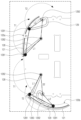
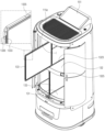
설명의 편의를 위해 상하 2개 층으로 나뉘어져 4개의 도어(120a, 120b, 120c, 120d)로 구성되는 실시예를 기준으로 설명하며, 4개의 도어(120a, 120b, 120c, 120d)는 동시에 또는 개별적으로 구동할 수 있다. 도 4 및 도 5은 본 발명의 일 실시 예에 따른 배송로봇(100)의 도어(120)가 개방된 상태를 도시한 도면이다. For convenience of explanation, an embodiment is described based on a configuration in which the door (120a, 120b, 120c, 120d) is divided into two upper and lower layers, and the four doors (120a, 120b, 120c, 120d) can be operated simultaneously or individually. FIGS. 4 and 5 are drawings illustrating a state in which the door (120) of a delivery robot (100) according to one embodiment of the present invention is open.
본 발명의 배송로봇(100)은 도 4에 도시된 바와 같이 일부 도어(120b, 120d)만 개방할 수도 있고, 도 5과 같이 모든 도어(120a, 120b, 120c, 120d)가 개방될 수도 있다. 도어(120)의 구동은 내부에 수납부(115)의 구획형태에 따라 달라질 수 있다. The delivery robot (100) of the present invention may open only some doors (120b, 120d) as shown in Fig. 4, or may open all doors (120a, 120b, 120c, 120d) as shown in Fig. 5. The operation of the door (120) may vary depending on the compartmentalized shape of the storage portion (115) inside.
수납부(115)가 파티션(133) 및 중간선반(132)를 통해 4개로 구획되면 각 도어(120a, 120b, 120c, 120d)가 개별적으로 구동하고, 파티션(133)이 생략되면 좌우 도어가 동시에 열려 하나의 수납부를 개방할 수 있다. 도 5의 실시예는 수납부(115) 구획되지 않고 하나의 큰 공간으로 구성된 경우로서, 모든 도어(120a, 120b, 120c, 120d)가 동시에 열릴 수 있다. When the storage unit (115) is divided into four by a partition (133) and a middle shelf (132), each door (120a, 120b, 120c, 120d) operates individually, and when the partition (133) is omitted, the left and right doors can open simultaneously to open one storage unit. The embodiment of Fig. 5 is a case where the storage unit (115) is not divided and is configured as one large space, and all doors (120a, 120b, 120c, 120d) can be opened simultaneously.
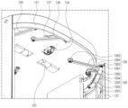
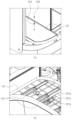
도 6은 본 발명의 일 실시예에 따른 배송로봇(100)의 수납부(115) 내부를 도시한 도면으로 도어패널(121)이 제거된 상태를 도시하고 있다.FIG. 6 is a drawing showing the inside of a storage section (115) of a delivery robot (100) according to one embodiment of the present invention, showing a state where the door panel (121) has been removed.
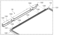
배송로봇(100)은 수납부(115)를 상하방향으로 구획하는 중간선반(132)과 좌우방향으로 구획하는 파티션(133)을 포함할 수 있다. 본 실시예의 배송로봇(100)은 중간선반(132)은 한 개, 파티션(133)은 2개를 포함할 수 있으며, 하나의 중간선반(132)과 두 개의 파티션(133)을 이용하여 도 6에 도시된 바와 같이 최대 4개의 수납부(115a, 115b, 115c, 115d)으로 구획할 수 있다. The delivery robot (100) may include a middle shelf (132) that divides the storage section (115) in the vertical direction and a partition (133) that divides the storage section (115) in the left-right direction. The delivery robot (100) of the present embodiment may include one middle shelf (132) and two partitions (133), and may be divided into a maximum of four storage sections (115a, 115b, 115c, 115d) using one middle shelf (132) and two partitions (133), as illustrated in FIG. 6.
중간선반(132) 및 파티션(133)은 바디 하우징(111)에 슬라이드 방식으로 탈착 가능하다. 중간선반(132)은 수납부(115)의 수직방향의 중앙에 삽입 가능하며, 중간선반(132)은 수납부(115)를 상부 수납부(115e)와 하부 수납부(115f)로 구획할 수 있다. The middle shelf (132) and the partition (133) can be detached and attached to the body housing (111) in a sliding manner. The middle shelf (132) can be inserted into the vertical center of the storage section (115), and the middle shelf (132) can divide the storage section (115) into an upper storage section (115e) and a lower storage section (115f).
여기서 의 수직방향의 중앙은 반드시 수치적으로 상부 수납부(115e)의 높이와 하부 수납부(115f)의 높이가 같다는 의미는 아니다. 다만, 후술할 파티션이 상부 수납부(115e)와 하부 수납부(115f)에 공용으로 이용하기 위해서는 상부 수납부(115e)와 하부 수납부(115f)가 동일한 높이를 가질 수 있다. Here, the vertical center does not necessarily mean that the height of the upper storage portion (115e) and the height of the lower storage portion (115f) are numerically equal. However, in order for the partition described below to be used in common with the upper storage portion (115e) and the lower storage portion (115f), the upper storage portion (115e) and the lower storage portion (115f) may have the same height.
중간선반(132)은 적재물건을 지지할 수 있도록 충분한 강성을 가져야 하며 소정의 두께를 가질 수 있다. 중간선반(132)을 지지하기 위해 수납부(115)의 좌우에 돌출된 선반 지지부(135, 도 12 참조)를 포함할 수 있다. The middle shelf (132) must have sufficient rigidity to support the loaded object and may have a predetermined thickness. In order to support the middle shelf (132), a shelf support member (135, see FIG. 12) protruding on the left and right sides of the storage section (115) may be included.
상부 수납부(115e)와 하부 수납부(115f)를 좌우로 구획하는 파티션(133)은 중간선반(132)에 형성된 가이드홈(1323)을 따라 삽입될 수 있다. 파티션(133)은 중간선반(132)과 달리 물품의 무게를 지지하지 않는 바, 두께는 중간선반(132)에 비해 상대적으로 얇게 형성할 수 있다. The partition (133) that divides the upper storage section (115e) and the lower storage section (115f) into left and right sections can be inserted along the guide groove (1323) formed in the middle shelf (132). Unlike the middle shelf (132), the partition (133) does not support the weight of the item, and thus can be formed to be relatively thinner than the middle shelf (132).
한 쌍의 파티션(133)과 모두 결합하기 위해 중간선반(132)은 상면과 하면에 모두 가이드홈(1323)이 형성될 수 있다. 수납부(115)의 상면과 하면에도 파티션(133)이 삽입되는 가이드홈(1125, 도 24 참조)이 형성될 수 있다. In order to be combined with a pair of partitions (133), the middle shelf (132) may have guide grooves (1323) formed on both the upper and lower surfaces. Guide grooves (1125, see FIG. 24) into which the partitions (133) are inserted may also be formed on the upper and lower surfaces of the storage portion (115).
파티션(133)은 가이드홈(1323)을 따라 수납부의 내측, 즉 후방으로 삽입되거나 전방으로 인출될 수 있다. 파티션(133)은 한 쌍이 상부 수납부(115e)와 하부 수납부(115f)에 각각 삽입될 수 있으며, 한 쌍의 파티션(133)은 독립적으로 탈착할 수 있다. The partition (133) can be inserted into the inside of the storage unit, i.e., rearwardly, or withdrawn forwardly, along the guide home (1323). A pair of partitions (133) can be inserted into each of the upper storage unit (115e) and the lower storage unit (115f), and a pair of partitions (133) can be independently detachable.
도 7은 본 발명의 일 실시예에 따른 배송로봇(100)의 수납부의 구획 방법을 도시한 개념도이다. 도 7의 (a)와 같이 하나의 중간선반(132)과 두 개의 의 파티션(133)을 이용하여 4개의 수납부(115a, 115b, 115c, 115d)로 구획할 수 있다. Fig. 7 is a conceptual diagram illustrating a method for dividing a storage compartment of a delivery robot (100) according to one embodiment of the present invention. As shown in Fig. 7 (a), the storage compartment can be divided into four storage compartments (115a, 115b, 115c, 115d) using one middle shelf (132) and two partitions (133).
도 7의 (b) 및 (c)와 같이 하나의 중간선반(132)과 하나의 파티션(133)을 이용하여 상부 수납부(115e)와 하부 수납부(115f) 중 일측은 연결된 공간으로 타측은 구획된 공간으로 이용할 수 있다. As shown in (b) and (c) of Fig. 7, one middle shelf (132) and one partition (133) can be used to connect one side of the upper storage section (115e) and the lower storage section (115f) and use the other side as a partitioned space.
또는 도 7의 (d)와 같이 상부 수납부(115e)와 하부 수납부(115f) 2개 공간으로만 구획할 수 있고, 도 7의 (e)와 같이 중간선반(132)과 파티션(133)을 모두 제거하여 큰 수납부(115)를 이용하여 이불과 같이 부피가 큰 물건을 배송할 수 있다. Or, as shown in (d) of Fig. 7, it can be divided into only two spaces, an upper storage section (115e) and a lower storage section (115f), and as shown in (e) of Fig. 7, the middle shelf (132) and the partition (133) can be removed to use the large storage section (115) to deliver bulky items such as blankets.
수납부(115)를 구획하면 수납 가능한 물품의 개수가 증가할 수 있으며, 작은 물건을 배송하는 경우 여러 목적지로 복수개의 물건을 한번에 배송할 수 있다. By dividing the storage compartment (115), the number of items that can be stored can increase, and when delivering small items, multiple items can be delivered to multiple destinations at once.
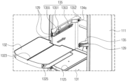
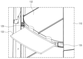
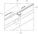
중간선반(132)이 삽입되어 상부 수납부(115e)와 하부 수납부(115f)가 구획된 경우 하부 수납부(115f)는 중간선반(132)에 가려서 내부가 보이지 않아 물건을 적재 또는 하차하기 위해 허리를 숙여야 한다. 이러한 불편함을 해소하고자 도 4에 도시된 바와 같이 하부에 슬라이딩 선반(131)이 전방으로 돌출되며 하부 선반에 적재된 물건을 쉽게 수령할 수 있다. When the middle shelf (132) is inserted to divide the upper storage section (115e) and the lower storage section (115f), the lower storage section (115f) is covered by the middle shelf (132) and the inside cannot be seen, so the user must bend down to load or unload items. To solve this inconvenience, as shown in Fig. 4, a sliding shelf (131) protrudes forward at the bottom, so that items loaded on the lower shelf can be easily received.
도 7의 (e)와 같이 수납부(115)가 구획되지 않은 경우 제어부(180)는 도 5와 같이 4개의 도어(120)를 동시에 개방하고 도 7의 (a) 내지 (d)와 같이 구획된 경우 제어부(180)는 다른 수납부(115)는 개방하지 않고, 선택된 수납부(115)만 개방하도록 도어(120)를 제어할 수 있다. When the storage unit (115) is not partitioned as in (e) of FIG. 7, the control unit (180) can open four doors (120) simultaneously as in FIG. 5, and when partitioned as in (a) to (d) of FIG. 7, the control unit (180) can control the door (120) to open only the selected storage unit (115) without opening other storage units (115).
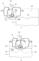
도 8은 본 발명의 일 실시예에 따른 배송로봇(100)의 도어 구동부(122, 1231, 1232, 124, 125, 128, 129)를 도시한 평면도이다. 좌측은 열린 상태 우측은 닫힌 상태를 도시하고 있다. 도어 구동부는 좌우방향으로 배치된 한 쌍의 도어패널(121a, 121b)을 각각 구동하기 위해 각각 구비될 수 있다. Fig. 8 is a plan view showing a door driving unit (122, 1231, 1232, 124, 125, 128, 129) of a delivery robot (100) according to one embodiment of the present invention. The left side shows an open state and the right side shows a closed state. The door driving unit may be provided to drive a pair of door panels (121a, 121b) arranged in the left and right directions, respectively.
또한, 도어(120)는 상하로도 나뉘어져 있으므로 상부 수납부(115e)를 커버하는 상부도어(120a, 120b)의 도어 구동부는 도어패널(121a, 121b)의 상측, 즉 수납부(115)의 상부에 위치할 수 있다. 하부 수납부(115f)를 커버하는 하부 도어(120cc, 120d)의 도어 구동부는 도어패널(121c, 121d)의 하측, 즉 수납부(115)의 하부에 위치할 수 있다. In addition, since the door (120) is divided into upper and lower parts, the door driving unit of the upper door (120a, 120b) covering the upper storage part (115e) can be located on the upper side of the door panel (121a, 121b), i.e., on the upper side of the storage part (115). The door driving unit of the lower door (120cc, 120d) covering the lower storage part (115f) can be located on the lower side of the door panel (121c, 121d), i.e., on the lower side of the storage part (115).
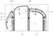
본 발명의 도어(120)는 닫힌 상태에서 상기 바디 수납부(115)를 커버하며 상기 바디 하우징(111)의 일측의 적어도 일부를 구성하는 도어패널(121), 제1 단부(end, 1281)는 도어패널(121)에 회전 가능하게 결합하고 제2 단부는 바디 하우징(111)에 회전 가능하게 결합된 제1 도어링크(128), 및 제1 도어링크(128)에 회전력을 제공하는 모터(122)를 포함한다. The door (120) of the present invention includes a door panel (121) that covers the body storage portion (115) in a closed state and constitutes at least a portion of one side of the body housing (111), a first door link (128) having a first end (1281) rotatably coupled to the door panel (121) and a second end rotatably coupled to the body housing (111), and a motor (122) that provides rotational force to the first door link (128).
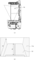
도어 구동부는 구동부 플레이트(125) 상에 배치될 수 있으며, 일부 구성은 구동부 플레이트(125)의 일면에 나머지 구성은 타면에 배치하거나, 모터(122)와 같이 두께가 있는 부재는 도어 구동부 플레이트(125)에 홀을 형성하여 배치할 수 있다. The door drive unit can be placed on the drive unit plate (125), and some components can be placed on one side of the drive unit plate (125) and the remaining components can be placed on the other side, or a thick member such as a motor (122) can be placed by forming a hole in the door drive unit plate (125).
본 실시예는 도 8에 도시된 바와 같이, 풀리(1231, 1232), 평벨트(124) 및 도어센서(1641, 1642)는 구동부 플레이트(125)의 일면에 도어링크(128, 129)는 구동부 플레이트(125)의 타면에 위치할 수 있다. 모터(122)는 두께를 고려하여 구동부 플레이트(125)에 홀을 형성하여 배치할 수 있다. 도어링크(128, 129)가 위치하는 구동부 플레이트(125)의 타면은 수납부(115)를 향하여 배치된다. In this embodiment, as illustrated in FIG. 8, pulleys (1231, 1232), flat belts (124), and door sensors (1641, 1642) may be positioned on one surface of a drive plate (125), and door links (128, 129) may be positioned on the other surface of the drive plate (125). The motor (122) may be positioned by forming a hole in the drive plate (125) considering the thickness. The other surface of the drive plate (125) where the door links (128, 129) are positioned is positioned toward the storage portion (115).
수납부(115)는 도어링크(128, 129) 및 후술할 슬라이딩 선반(131)의 구동부를 커버 위해 수납부 하우징(112, 도 24 참조)을 포함할 수 있다. 수납부 하우징(112)은 바닥면을 구성하는 수납부 베이스(1123, 도 24 참조)와 상면을 구성하는 수납부 실링(1122, 도 18 참조)을 포함할 수 있다. 도어링크는 수납부 베이스(1123)의 하부에 수납부 실링(1122)의 상부에 위치할 수 있다. The storage unit (115) may include a storage unit housing (112, see FIG. 24) to cover the driving unit of the door link (128, 129) and the sliding shelf (131) to be described later. The storage unit housing (112) may include a storage unit base (1123, see FIG. 24) forming a bottom surface and a storage unit sealing (1122, see FIG. 18) forming an upper surface. The door link may be located on the lower portion of the storage unit base (1123) and the upper portion of the storage unit sealing (1122).
도어패널(121)은 바디 수납부(115)를 커버하는 부재로서 닫힌 상태에서 바디 하우징(111)과 연속적인 면을 형성하여 바디(110)의 외관을 구성할 수 있다. 도어패널(121)은 물건을 수납 및 수령이 용이하도록 바디 하우징(111)의 전면에서 좌우 방향으로 조금 더 넓게 형성할 수 있다. The door panel (121) is a member that covers the body storage portion (115) and can form a continuous surface with the body housing (111) when closed to configure the exterior of the body (110). The door panel (121) can be formed slightly wider in the left and right directions from the front of the body housing (111) to facilitate storing and receiving items.
도어패널(121)은 바디 하우징(111)의 전면 보다 더 연장되어 측면 방향으로 꺾어질 수 있다. 이하에서는 설명의 편의를 위해 도어패널(121)의 닫히는 방향의 엣지를 제1 도어엣지(1211), 도어패널(121)의 열리는 방향의 엣지를 제2 도어엣지(1212)라 한다. The door panel (121) may extend further than the front of the body housing (111) and may be bent in a lateral direction. For convenience of explanation, the edge of the door panel (121) in the closing direction is referred to as the first door edge (1211), and the edge of the door panel (121) in the opening direction is referred to as the second door edge (1212).
모터(122)는 링크와 직접 연결될 수도 있으나, 도 9에 도시된 바와 같이 한 쌍의 풀리(1231, 1232)와 한 쌍의 풀리(1231, 1232)를 감싸는 평벨트(124)를 포함할 수 있다. 평벨트(124)는 한 쌍의 풀리(1231, 1232)를 동기화 시킨다. 모터(122)와 연결된 제1 풀리(1231)는 회전하며 평벨트(124)는 제1 풀리(1231)의 외주면을 따라 이동한다. The motor (122) may be directly connected to the link, but may include a pair of pulleys (1231, 1232) and a flat belt (124) wrapping the pair of pulleys (1231, 1232), as shown in FIG. 9. The flat belt (124) synchronizes the pair of pulleys (1231, 1232). The first pulley (1231) connected to the motor (122) rotates, and the flat belt (124) moves along the outer surface of the first pulley (1231).
평벨트(124)를 통해 회전력이 전달되어 제2 풀리(1232)가 회전하고 제2 풀리(1232)는 제1 도어링크(128)의 제2 단부(1282)와 결합한다. 제1 도어링크(128)는 제2 풀리(1232)의 회전에 따라 제2 풀리(1232)의 회전축을 중심으로 회동하며 제1 도어링크(128)의 제1 단부(1281)는 제2 풀리(1232)의 회전축을 중심으로 하는 호를 그리며 회전할 수 있다. Rotational force is transmitted through the flat belt (124) to rotate the second pulley (1232), and the second pulley (1232) is coupled with the second end (1282) of the first door link (128). The first door link (128) rotates around the rotational axis of the second pulley (1232) according to the rotation of the second pulley (1232), and the first end (1281) of the first door link (128) can rotate in an arc centered around the rotational axis of the second pulley (1232).
이하에서 설명의 편의를 위해 제1 도어링크(128)가 도어패널(121)이 열리는 방향으로 회전하는 방향을 제1 회전방향, 도어패널(121)이 닫히는 방향으로 제1 도어링크(128)가 회전하는 방향을 제2 회전방향이라 한다. For convenience of explanation below, the direction in which the first door link (128) rotates in the direction in which the door panel (121) opens is referred to as the first rotation direction, and the direction in which the first door link (128) rotates in the direction in which the door panel (121) closes is referred to as the second rotation direction.
도어(120)의 좌우 방향에 따라 제1 회전방향은 시계방향이 될 수 도 있고, 반시계 방향이 될 수도 있다. 도 8의 좌측에 도시된 제1 도어링크(128)의 제1 회전방향은 반시계 방향, 제2 회전방향은 시계방향이다. Depending on the left and right direction of the door (120), the first rotation direction can be clockwise or counterclockwise. The first rotation direction of the first door link (128) shown on the left side of Fig. 8 is counterclockwise, and the second rotation direction is clockwise.
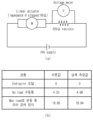
평벨트(124)는 벨트에 돌기가 형성되지 않은 테이프 형상을 가지며 제1 풀리(1231)와 제2 풀리(1232)의 외측면에도 톱니가 형성되어 있지 않다. 평벨트(124)와 제1 풀리(1231) 및 제2 풀리(1232) 사이의 마찰력을 이용하여 평벨트(124)가 이동할 수 있으며 마찰력보다 큰 외력이 가해지면 평벨트(124)는 제2 풀리(1232)와 슬립이 일어날 수 있다. The flat belt (124) has a tape shape without any projections formed on the belt, and no teeth are formed on the outer surfaces of the first pulley (1231) and the second pulley (1232). The flat belt (124) can move by utilizing the frictional force between the flat belt (124) and the first pulley (1231) and the second pulley (1232), and when an external force greater than the frictional force is applied, the flat belt (124) can slip with the second pulley (1232).
도어(120)에 물건이나 손이 끼인 경우 도어패널(121)이 움직이지 못하여 제2 풀리(1232)가 회전할 수 없다. 제2 풀리(1232)의 회전이 제한되면, 평벨트(124)와 슬립이 발생한다. 즉, 모터(122)가 제1 풀리(1231)를 회전 시키더라도 제2 풀리(1232)는 회전하지 않을 수 있다. If an object or hand is caught in the door (120), the door panel (121) cannot move, and thus the second pulley (1232) cannot rotate. If the rotation of the second pulley (1232) is restricted, slip occurs with the flat belt (124). In other words, even if the motor (122) rotates the first pulley (1231), the second pulley (1232) may not rotate.
돌기가 형성된 벨트를 이용하면 물건이 끼어 도어패널(121)이 멈춘 경우 모터(122)가 회전하지 못하여 역기전력이 가해지는 문제가 있다. 평벨트(124)와 제2 풀리(1232) 사이에 슬립이 가능하여 모터(122)에 역기전력에 의한 고장을 방지할 수 있다. When using a belt with a protrusion formed, there is a problem that when an object gets caught and the door panel (121) stops, the motor (122) cannot rotate and counter electromotive force is applied. Slipping is possible between the flat belt (124) and the second pulley (1232), so that a failure due to counter electromotive force can be prevented from occurring in the motor (122).
제1 풀리(1231)의 직경을 제2 풀리(1232)보다 작게 형성하여 모터의 회전수와 제2 풀리의 이동량을 맞출 수 있다. 제1 풀리(1231)는 도어(120)가 닫힌 상태에서 열린 상태까지 전환하는데 약 120° 정도만 회전할 수 있으며, 제1 풀리(1231)는 제2 풀리(1232)보다 작으므로 복수 회 회전할 수 있다. The diameter of the first pulley (1231) can be made smaller than that of the second pulley (1232) so that the rotational speed of the motor and the movement amount of the second pulley can be matched. The first pulley (1231) can only rotate about 120° to switch the door (120) from a closed state to an open state, and since the first pulley (1231) is smaller than the second pulley (1232), it can rotate multiple times.
제2 풀리(1232)는 외주면에서 돌출된 센싱돌기(1233)를 포함할 수 있다. 센싱돌기(1233)는 제2 풀리(1232)의 회전에 따라 위치가 달라질 수 있으며, 닫힌 상태에서 센싱돌기(1233)와 접하는 닫힘감지센서(1641)와 열린 상태에서 센싱돌기(1233)와 접하는 열림감지센서(1642)를 포함할 수 있다. The second pulley (1232) may include a sensing projection (1233) protruding from the outer surface. The sensing projection (1233) may have a different position depending on the rotation of the second pulley (1232), and may include a closing detection sensor (1641) that comes into contact with the sensing projection (1233) in a closed state and an opening detection sensor (1642) that comes into contact with the sensing projection (1233) in an open state.
도 8의 우측의 도어패널(121)은 닫힌상태로 우측의 제2 풀리(1232)의 센싱돌기(1233)는 닫힘감지 센서와 닿은 상태이다. 제어부(180)는 닫힘감지센서(1641)가 ON되면 도어패널(121)이 바디 개구부를 완전히 커버한 것으로 판단하고 배송로봇(100)을 주행할 수 있다. The door panel (121) on the right side of Fig. 8 is closed, and the sensing protrusion (1233) of the second pulley (1232) on the right side is in contact with the closing detection sensor. When the closing detection sensor (1641) is turned on, the control unit (180) determines that the door panel (121) completely covers the body opening and can drive the delivery robot (100).
한편, 좌측의 도어패널(121)은 열린 상태로 좌측 센싱돌기(1233)는 열림감지센서(1642)와 닿은 상태이다. 제어부(180)는 열림감지센서(1642)가 ON이 된 것을 감지하여 도어패널(121)이 완전히 열린 것으로 판단하고 슬라이딩 선반(131)을 인출할 수 있다. Meanwhile, the left door panel (121) is in an open state and the left sensing protrusion (1233) is in contact with the opening detection sensor (1642). The control unit (180) detects that the opening detection sensor (1642) is turned ON, determines that the door panel (121) is completely open, and can withdraw the sliding shelf (131).
제1 도어링크(128)의 제1 단부(1281) 는 도어패널(121)에 회전 가능하게 결합할 수 있다. 상부도어(120a, 120b)의 도어 구동부는 수납부(115)의 상측에 위치하므로 도어패널(121)의 상단에 제1 도어링크(128)의 제1 단부(1281)가 결합할 수 있다. 하부도어(120c, 120d)의 도어 구동부는 수납부(115)의 하측에 위치하는 바, 도어패널(121)의 하단에 제1 도어링크(128)의 제1 단부(1281)가 결합할 수 있다. The first end (1281) of the first door link (128) can be rotatably coupled to the door panel (121). Since the door drive unit of the upper door (120a, 120b) is located above the storage unit (115), the first end (1281) of the first door link (128) can be coupled to the upper end of the door panel (121). Since the door drive unit of the lower door (120c, 120d) is located below the storage unit (115), the first end (1281) of the first door link (128) can be coupled to the lower end of the door panel (121).
본 발명은 도어패널(121)이 열리면서 바디 하우징(111)의 외측면을 따라 측방향으로 각도가 변화하면서 슬라이딩하도록 구성하여 도어패널(121)이 바디 하우징(111)과 간섭되는 것을 방지할 수 있다. The present invention can prevent the door panel (121) from interfering with the body housing (111) by configuring it to slide laterally along the outer surface of the body housing (111) at a different angle when the door panel (121) is opened.
제1 도어링크(128)가 도어패널(121)을 오픈 시 도어패널(121)이 향하는 방향을 전환하며 슬라이딩 오픈 되도록, 제2 도어링크(129)를 더 포함할 수 있다. 제2 도어링크(129)는 제1 도어링크(128)에 의해 도어패널(121)이 측방향으로 밀리는 힘을 회전력으로 전환하여, 도어패널(121)의 제2 엣지가 바디(110)의 후방으로 향하도록 가이드 한다. The first door link (128) may further include a second door link (129) so that the door panel (121) can slide open while changing the direction in which the door panel (121) faces when opening the door panel (121). The second door link (129) converts the force that pushes the door panel (121) laterally by the first door link (128) into a rotational force, thereby guiding the second edge of the door panel (121) to face the rear of the body (110).
도어패널(121)의 제1 도어엣지(1211)는 닫힌 상태에서 바디 개구부의 중앙에 열린 상태에서 바디 개구부의 측방향에 위치할 수 있다. 제1 도어링크(128)의 제1 단부(1281)는 닫힌 상태에서 열린 상태로 전환 시 바디 하우징(111)과 간섭 없이 바디 개구부를 따라 이동하기 위해 도어패널(121)의 제1 도어엣지(1211)에 결합할 수 있다. The first door edge (1211) of the door panel (121) can be positioned at the center of the body opening in the closed state and at the side of the body opening in the open state. The first end (1281) of the first door link (128) can be coupled to the first door edge (1211) of the door panel (121) so as to move along the body opening without interference with the body housing (111) when transitioning from the closed state to the open state.
제2 도어링크(129)의 제1 단부(1291)는 도어패널(121)에 결합하고 제2 단부는 바디 하우징(111)에 결합하며, 제2 도어링크(129)의 제1 단부(1291) 및 결합하고 제2 단부는 제1 도어링크(128)의 제1 단부(1281) 및 제2 단부(1282)와 이격된 위치에서 도어패널(121) 및 바디 하우징(111)에 연결된다. The first end (1291) of the second door link (129) is coupled to the door panel (121) and the second end is coupled to the body housing (111). The first end (1291) of the second door link (129) and the second end are coupled to the door panel (121) and the body housing (111) at a position spaced apart from the first end (1281) and the second end (1282) of the first door link (128).
도 8에 도시된 바와 같이 제2 도어링크(129)의 제1 단부(1291)는 도어패널(121)의 꺾어진 부분, 즉 전면에 위치하는 도어 전면부와 측면면에 위치하는 도어 측면부 사이에 체결될 수 있다. As illustrated in FIG. 8, the first end (1291) of the second door link (129) can be fastened between the bent portion of the door panel (121), that is, the front portion of the door located at the front and the side portion of the door located at the side.
제1 도어링크(128)에 의해 도어패널(121)이 측방향으로 이동 시 제2 도어링크(129)는 회전하면서 도어패널(121)의 각도를 변경시킬 수 있다. 제2 도어링크(129)는 제1 도어링크(128)와 같은 방향으로 회전하며, 도어패널(121)은 한 쌍의 도어링크(128, 129)의 연동을 통해 닫힌 상태와 열린 상태로 전환할 수 있다. When the door panel (121) moves laterally by the first door link (128), the second door link (129) can change the angle of the door panel (121) by rotating. The second door link (129) rotates in the same direction as the first door link (128), and the door panel (121) can be switched between a closed state and an open state through the linkage of a pair of door links (128, 129).
도 9는 본 발명의 일 실시 예에 따른 배송로봇(100)의 링크의 동작을 설명하기 위한 개념도이다. 좌측은 열린 상태이고 우측은 닫힌 상태를 도시하고 있다. Figure 9 is a conceptual diagram for explaining the operation of a link of a delivery robot (100) according to one embodiment of the present invention. The left side shows an open state and the right side shows a closed state.
제1 도어링크(128)와 제2 도어링크(129)는 절곡된 형상을 가지고 있으나, 각 링크의 단부(1281, 1282, 1291, 1292) 사이의 간격(L1, L2)은 일정하다. 또한, 제1 도어링크(128)의 제1 단부(1281)와 제2 도어링크(129)의 제1 단부(1291)는 도어(120)에 결합되어 제1 거리(D1)가 일정하고, 제1 도어링크(128)의 제2 단부(1282)와 제2 도어링크(129)의 제2 단부(1292)는 바디 하우징(111)에 결합되어 제2 거리(D2)가 일정하다. The first door link (128) and the second door link (129) have a bent shape, but the gap (L1, L2) between the ends (1281, 1282, 1291, 1292) of each link is constant. In addition, the first end (1281) of the first door link (128) and the first end (1291) of the second door link (129) are coupled to the door (120) so that the first distance (D1) is constant, and the second end (1282) of the first door link (128) and the second end (1292) of the second door link (129) are coupled to the body housing (111) so that the second distance (D2) is constant.
제1 거리(D1)와 제2 거리(D2)가 고정되어 있고 제1 간격(L1)과 제2 간격(L2)일정하므로 제1 거리(D1), 제2 거리(D2), 제1 간격(L1) 및 제2 간격(L2)을 4개의 변으로 하는 사각형을 이루며 사각형의 내각이 변화하면서 형상이 변화하는 형태로 제1 도어링크(128)와 제2 도어링크(129)가 회전한다. Since the first distance (D1) and the second distance (D2) are fixed and the first interval (L1) and the second interval (L2) are constant, the first distance (D1), the second distance (D2), the first interval (L1), and the second interval (L2) form a square with four sides, and the first door link (128) and the second door link (129) rotate in a manner in which the shape changes as the internal angle of the square changes.
닫힌 상태에서 열린 상태로 전환 시, 제1 도어링크(128)는 모터(122)의 회전력을 받아 제1 단부(1281)가 제1 궤적(T1)을 그리며 회전한다. 제1 도어링크(128)는 도어패널(121)을 바깥쪽 방향(열리는 방향)으로 밀고, 제2 도어링크(129)는 도어패널(121)에 결합된 제1 단부(1291)가 제1 도어링크(128)의 제1 단부(1281)와 제1 거리(D1)를 유지하면서 제2 궤적(T2)을 따라 회전한다.When switching from a closed state to an open state, the first door link (128) receives the rotational force of the motor (122) and the first end (1281) rotates along a first trajectory (T1). The first door link (128) pushes the door panel (121) outwardly (in the opening direction), and the second door link (129) rotates along a second trajectory (T2) while maintaining a first distance (D1) from the first end (1281) of the first door link (128).
도 10은 제1 도어링크(128)의 제1 간격(L1)과 제2 도어링크(129)의 제2 간격(L2)에 따른 도어(120)의 궤도를 도시한 도면으로 (a)는 도 9의 실시예에 따른 제1 도어링크(128)의 양 단부는 제1 간격(L1)을 이루도록 배치되고 제2 도어링크(129)의 양 단부는 제2 간격(L2)을 가지도록 배치된 도면이다. (b)는 제1 간격(L1')이 (a)의 실시예 보다 긴 경우이고, (c)는 제2 간격(L2”)이 (a)의 실시예 보다 긴 경우를 도시하고 있다. FIG. 10 is a drawing showing an orbit of a door (120) according to a first gap (L1) of a first door link (128) and a second gap (L2) of a second door link (129). (a) is a drawing in which both ends of the first door link (128) according to the embodiment of FIG. 9 are arranged to form a first gap (L1) and both ends of the second door link (129) are arranged to have a second gap (L2). (b) is a drawing in which the first gap (L1') is longer than in the embodiment of (a), and (c) is a drawing in which the second gap (L2”) is longer than in the embodiment of (a).
(b)와 같이 (a)의 실시예보다 제1 도어링크(128)의 제1 간격(L1')이 길고 제2 도어링크(129)의 제2 간격(L2')이 짧으면 도어(120)의 제1 도어엣지(1211)의 회전반경이 길어져 도어(120)가 슬라이드 이동하지 않고 여닫이 문과 같이 회전하며 열릴 수 있다. As in (b), if the first gap (L1') of the first door link (128) is longer and the second gap (L2') of the second door link (129) is shorter than in the embodiment of (a), the rotation radius of the first door edge (1211) of the door (120) is longer, so that the door (120) can open by rotating like a swing door without sliding.
(c)와 같이 (a)의 실시예보다 제2 도어링크(129)의 제2 간격(L2”)이 길면 도어패널(121)의 수평상태를 유지하며 측방향으로 도어(120)가 오픈될 수 있다. As in (c), if the second gap (L2”) of the second door link (129) is longer than in the embodiment of (a), the door (120) can be opened laterally while maintaining the horizontal state of the door panel (121).
도 10의 (b)와 같이 제1 간격(L1')의 길이가 너무 길면 여닫이 도어(120)가 되고, 도 10의 (c)와같이 제1 간격(L1”)이 제2 간격(L2”)보다 짧으면 도어패널(121)이 수평방향을 유지하며 회동하거나 오히려 제2 도어엣지(1212)가 전방으로 돌출될 수 있다. If the length of the first gap (L1') is too long, as in (b) of FIG. 10, it becomes a swing door (120), and if the first gap (L1”) is shorter than the second gap (L2”), as in (c) of FIG. 10, the door panel (121) rotates while maintaining the horizontal direction, or the second door edge (1212) may protrude forward.
도어패널(121)의 슬라이드 이동 시 제2 도어엣지(1212)가 후방으로 밀리면서 바디 하우징(111)의 측면에 가깝게 이동하기 위해서는 (a)와 같이 제1 도어링크(128)의 제1 간격(L1)은 제2 도어링크(129)의 제2 간격(L2)보다 조금 긴 정도가 적절하다. In order for the second door edge (1212) to be pushed rearward and moved closer to the side of the body housing (111) when the door panel (121) slides, the first gap (L1) of the first door link (128) is appropriately slightly longer than the second gap (L2) of the second door link (129), as in (a).
도 11은 본 발명의 일 실시 예에 따른 배송로봇(100)의 도어 구동부를 하측에서 바라본 도면이다. 도 11을 참조하면, 제1 도어링크(128)는 제1 단부(1281)에 위치하는 제1 부분(1283)과 제2 단부(1282) 방향에 위치하는 제2 부분(1284)이 소정의 각도를 이루며 꺾인 형태를 가질 수 있다. 제1 부분(1283)은 제1 단부(1281)에 인접한 위치로 제2 부분(1284)에 비해 상대적으로 짧은 길이를 가진다. Fig. 11 is a drawing of a door drive unit of a delivery robot (100) according to an embodiment of the present invention, viewed from below. Referring to Fig. 11, the first door link (128) may have a shape in which a first part (1283) located at a first end (1281) and a second part (1284) located in the direction of a second end (1282) are bent at a predetermined angle. The first part (1283) is located adjacent to the first end (1281) and has a relatively shorter length than the second part (1284).
제1 도어링크(128)의 제1 단부(1281)는 도어패널(121)의 제1 도어엣지(1211)에 결합되므로 도어(120)가 개방된 상태에서 제1 도어링크(128)의 제1 부분(1283)이 외측으로 노출된다. 외측으로 노출되는 제1 부분(1283)이 가능한 최소로 보이도록 도어패널(121)의 내측면에 가깝게 배치하는 것이 바람직하다. The first end (1281) of the first door link (128) is connected to the first door edge (1211) of the door panel (121), so that the first part (1283) of the first door link (128) is exposed to the outside when the door (120) is open. It is preferable to place the first part (1283) exposed to the outside as close to the inner surface of the door panel (121) as possible so that it is visible as little as possible.
도 8에 도시된 바와 같이 제1 도어링크(128)의 제1 부분(1283)은 도어패널(121)의 제1 도어엣지(1211)를 향해 꺾어지도록 구성할 수 있다. 제1 단부(1281)는 닫힌 상태에서 도어패널(121)의 내측면과 평행하게 배치되도록 구성하고 열린 상태에서는 회전하므로 도어패널(121)의 내측면에서 이격되나 제1 부분과 제2 부분(1284)이 직선인 상태보다 도어패널(121)에 인접하여 외측으로 노출되는 정도를 감소시킬 수 있다. As illustrated in FIG. 8, the first part (1283) of the first door link (128) can be configured to be bent toward the first door edge (1211) of the door panel (121). The first end (1281) is configured to be arranged parallel to the inner surface of the door panel (121) in the closed state and rotates in the open state, so that although it is spaced from the inner surface of the door panel (121), the degree of exposure to the outside by being adjacent to the door panel (121) can be reduced compared to the state where the first part and the second part (1284) are in a straight line.
제2 도어링크(129)는 U형으로 꺾여 제1 단부(1291)와 제2 단부(1292)가 같은 방향을 향할 수 있다. 제2 도어링크(129)의 제2 단부(1292)는 도 8에 도시된 바와 같이 열린 상태에서 바디 하우징(111)의 측방향에 위치할 수 있으며 도어의 제2 엣지(1212)를 후방으로 이동시킨다.The second door link (129) may be bent into a U shape so that the first end (1291) and the second end (1292) face the same direction. The second end (1292) of the second door link (129) may be positioned laterally of the body housing (111) in the open state as shown in FIG. 8 and moves the second edge (1212) of the door rearward.
제2 도어링크(129)가 바디 하우징(111)과 간섭 없이 배치되려면, 제2 도어링크(129)는 U자로 휘어진 절곡부(1295, 도 11)를 포함하고 제1 단부(1291)와 제2 단부(1292)가 같은 방향을 향할 수 있다. In order for the second door link (129) to be positioned without interference with the body housing (111), the second door link (129) may include a U-shaped bent portion (1295, FIG. 11) and the first end (1291) and the second end (1292) may face the same direction.
제1 단부(1291)를 포함하는 제1 부분(1293)은 제2 도어링크(129)의 회전운동을 주도하는 부분이므로 제2 단부(1292)를 포함하는 제2 부분(1294) 보다 길고 제2 부분(1294)은 바디 하우징(111)과 간섭을 피할 수 있는 길이를 가질 수 있다. 도어(120)가 열린 상태에서 도 8의 좌측의 도어(120b)와 같이 제2 도어링크(129)의 제1 부분(1293)과 제2 부분(1294) 사이에 바디 하우징(111)이 위치할 수 있다. The first part (1293) including the first end (1291) is a part that drives the rotational movement of the second door link (129), and therefore, it is longer than the second part (1294) including the second end (1292), and the second part (1294) can have a length that can avoid interference with the body housing (111). When the door (120) is open, the body housing (111) can be positioned between the first part (1293) and the second part (1294) of the second door link (129), as in the door (120b) on the left side of FIG. 8.
제2 도어링크(129)는 모터(122)와 직접적으로 연결되지 않으나, 도어패널(121)이 흔들리지 않고 정해진 궤도로 열리도록 가이드한다. 제1 도어링크(128)는 모터(122)의 배치로 인하여 도어패널(121)의 상측 또는 하측에만 위치하나 제2 도어링크(129)는 도어패널(121)의 상측과 하측에 모두 결합할 수 있다(도 5 참조).The second door link (129) is not directly connected to the motor (122), but guides the door panel (121) to open along a set path without shaking. The first door link (128) is located only on the upper or lower side of the door panel (121) due to the arrangement of the motor (122), but the second door link (129) can be connected to both the upper and lower sides of the door panel (121) (see FIG. 5).
즉, 제2 도어링크(129)는 수납부(115)의 상측 및 하측 외에 중간에 위치할 수 있다. 도 6을 참고하면 수납부(115)의 중간에 위치하는 제2 도어링크(129)는 한 쌍이 상하방향으로 배치되어 하나는 상부도어(120a, 120b)와 다른 하나는 하부도어(120c, 120d)와 연결될 수 있다. That is, the second door link (129) may be located in the middle of the storage section (115) in addition to the upper and lower sides. Referring to Fig. 6, the second door link (129) located in the middle of the storage section (115) may be arranged in a pair in the upper and lower directions so that one may be connected to the upper door (120a, 120b) and the other to the lower door (120c, 120d).
도 6을 참고하면 제2 도어링크(129)는 중간선반(132)의 양측에 위치할 수 있으며, 중간선반(132)은 제2 도어링크(129)가 회전할 수 있는 공간을 제공하기 위해 좌우에 홈을 포함할 수 있다. Referring to FIG. 6, the second door link (129) may be positioned on both sides of the middle shelf (132), and the middle shelf (132) may include grooves on the left and right sides to provide a space in which the second door link (129) can rotate.
중간선반(132)이 분리된 경우 제2 도어링크(129)가 노출되지 않도록 제2 도어링크(129)를 커버하기 위한 링크커버(1351)를 더 포함할 수 있으며, 링크커버(1351)는 중간선반(132)을 지지하는 선반 지지부(135)로서 역할을 할 수 있다(도 12 참조).When the middle shelf (132) is separated, a link cover (1351) may be further included to cover the second door link (129) so that the second door link (129) is not exposed, and the link cover (1351) may serve as a shelf support member (135) that supports the middle shelf (132) (see FIG. 12).
도어 구동부는 평벨트(124)를 이용하므로 제2 풀리(1232)와 평벨트(124) 사이에 슬립이 일어나면서 도어패널(121)이 열릴 수 있다. 또한, 물품수령자가 아닌 제3 자가 도어(120)를 강제로 열어서 물품을 가져갈 수 있다. Since the door drive unit uses a flat belt (124), the door panel (121) can be opened when slip occurs between the second pulley (1232) and the flat belt (124). In addition, a third party other than the recipient of the goods can forcibly open the door (120) and take the goods.
따라서 도어(120)를 잠그는 잠금장치가 필요하며, 도 11에 도시된 바와 같이 제1 도어링크(128)의 회전을 제한하는 잠금레버(127)를 구비할 수 있다. 잠금레버(127)는 선택적으로 제1 도어링크(128)의 궤적 상에 인입출 될 수 있다. 잠금 상태에서 열림 상태로 회전하지 못하도록 잠금 상태에서 열림 상태로 전환하는 제1 회전방향에 잠금레버(127)가 위치할 수 있다. Therefore, a locking device for locking the door (120) is required, and a locking lever (127) for limiting the rotation of the first door link (128) as shown in Fig. 11 may be provided. The locking lever (127) may be selectively inserted and withdrawn along the trajectory of the first door link (128). The locking lever (127) may be positioned in the first rotation direction for switching from the locked state to the open state to prevent rotation from the locked state to the open state.
잠금레버(127)가 선택적으로 제1 도어링크(128)의 제1 회전방향에 위치하도록 제어하는 잠금모터(122)는 닫힘감지센서(1641)가 ON되는 경우 구동하여 잠금레버(127)를 돌출시키고, 도어(120)열림 명령이 입력된 경우 제1 도어링크(128)가 제1 회전방향으로 회전 가능하게 잠금모터(122)는 잠금레버(127)를 인입할 수 있다(도 11의 우측 도어(120b) 참고). The lock motor (122) that controls the lock lever (127) to be selectively positioned in the first rotation direction of the first door link (128) is driven when the closing detection sensor (1641) is turned ON to protrude the lock lever (127), and when a door (120) opening command is input, the lock motor (122) can retract the lock lever (127) so that the first door link (128) can rotate in the first rotation direction (see the right door (120b) of FIG. 11).
이는 배송로봇(100)의 작도오류로 인하여 도어(120)가 구동하지 못하는 경우 수동으로 도어(120)를 개방해야 하는 비상상황에서 잠금을 해제하기 위해 잠금레버(127)는 수동으로 인입할 수 있다. 도어패널(121)의 상단 또는 하단에 자와 같이 얇고 긴 부재를 넣어 잠금레버(127)를 밀면 잠금레버(127)가 제1 도어링크(128)와 간섭이 없도록 인입되며 수동으로 도어패널(121)을 개방할 수 있다. In an emergency situation where the door (120) cannot be operated due to a design error of the delivery robot (100) and the door (120) must be opened manually, the lock lever (127) can be manually inserted to release the lock. When a thin and long member such as a ruler is inserted into the top or bottom of the door panel (121) and the lock lever (127) is pushed, the lock lever (127) is inserted without interference with the first door link (128), and the door panel (121) can be opened manually.
도 6 내지 도 7에서 살펴본 바와 같이 본 발명의 수납부(115)를 상하로 구획하는 중간선반(132)과 좌우로 구획하는 파티션(133)을 포함할 수 있으며, 중간선반(132)과 파티션(133)은 선택적으로 바디 하우징(111)에 결합할 수 있다. 이하에서는 중간선반(132) 및 파티션(133)의 결합 방법에 대해 구체적으로 살펴보도록 한다. As examined in FIGS. 6 and 7, the storage unit (115) of the present invention may include a middle shelf (132) that divides the upper and lower parts and a partition (133) that divides the left and right parts, and the middle shelf (132) and the partition (133) may be selectively coupled to the body housing (111). Hereinafter, a method of coupling the middle shelf (132) and the partition (133) will be specifically examined.
도 12는 본 발명의 일 실시예에 따른 배송로봇(100)의 중간선반(132)의 결합방법을 도시한 도면이다. 도 12에 도시된 바와 같이 중간선반(132)은 전방에서 슬라이드 방식으로 삽입하여 결합할 수 있다. Fig. 12 is a drawing illustrating a method of joining an intermediate shelf (132) of a delivery robot (100) according to one embodiment of the present invention. As illustrated in Fig. 12, the intermediate shelf (132) can be joined by slidingly inserting it from the front.
중간선반(132)을 지지하는 선반 지지부(135)는 수납부(115)에 양 측방향에 배치될 수 있다. 중간선반(132)은 좌우 측방향에서 오목하게 인입되어, 선반레일(1325)을 포함하며, 선반레일(1325)에 선반 지지부(135)가 위치한 상태로 중간선반(132)가 삽입될 수 있다. 선반레일(1325)은 선반 지지부(135)의 돌출된 높이에 상응한 깊이로 인입될 수 있다.The shelf support member (135) supporting the middle shelf (132) can be arranged on both sides of the storage unit (115). The middle shelf (132) is recessed in the left and right sides and includes a shelf rail (1325), and the middle shelf (132) can be inserted with the shelf support member (135) positioned on the shelf rail (1325). The shelf rail (1325) can be retracted to a depth corresponding to the protruding height of the shelf support member (135).
전술한 바와 같이 제2 도어링크(129)는 수납부(115)의 상부와 하부뿐만 아니라 수납부(115)의 중간에 위치할 수 있으며, 중간선반(132)의 좌우 방향에 배치될 수 있다. As described above, the second door link (129) can be located not only at the top and bottom of the storage section (115) but also in the middle of the storage section (115), and can be arranged in the left and right directions of the middle shelf (132).
중간선반(132)을 수납부(115)에 체결시 제2 도어링크(129)와 간섭이 일어나지 않도록 선반 지지부(135)는 제2 도어링크(129)를 커버하는 링크커버(1351)를 포함할 수 있다. 링크커버(1351)는 제2 도어링크(129)가 파손되지 않도록 보호하며, 도 12와 같이 중간선반(132)을 수납부(115)에서 제거한 상태에서 링크커버(1351)는 제2 도어링크(129)가 외부로 노출되는 것을 최소화 할 수 있다. 링크커버(1351)는 선반 지지부(135)의 바디 개구부와 인접한 전방에 배치될 수 있다. When the middle shelf (132) is fastened to the storage unit (115), the shelf support unit (135) may include a link cover (1351) that covers the second door link (129) so that interference with the second door link (129) does not occur. The link cover (1351) protects the second door link (129) from being damaged, and when the middle shelf (132) is removed from the storage unit (115) as shown in FIG. 12, the link cover (1351) can minimize the second door link (129) from being exposed to the outside. The link cover (1351) may be placed in front adjacent to the body opening of the shelf support unit (135).
제2 도어링크(129)의 가동범위에 상응하여 링크커버(1351)는 돌출될 수 있다. 중간선반(132)의 선반레일(1325)은 링크커버(1351)의 전 구간을 통과할 수 있어야 하는 바, 선반레일(1325)은 링크커버(1351)의 돌출된 높이에 상응하는 깊이를 가질 수 있다.The link cover (1351) can be protruded in accordance with the range of motion of the second door link (129). The shelf rail (1325) of the middle shelf (132) must be able to pass through the entire section of the link cover (1351), and the shelf rail (1325) can have a depth corresponding to the protruding height of the link cover (1351).
중간선반(132)의 장착여부를 감지하기 위해 선반 지지부(135)는 탄성센서(134)를 구비할 수 있다. 탄성센서(134)는 중간선반(132)이 삽입되면 가압되어 눌리면서 중간선반(132)이 선반 지지부(135)에 결합된 것을 감지할 수 있다. In order to detect whether the middle shelf (132) is mounted, the shelf support (135) may be equipped with an elastic sensor (134). The elastic sensor (134) may be pressed when the middle shelf (132) is inserted, thereby detecting that the middle shelf (132) is coupled to the shelf support (135).
후술할 파티션(133)의 장착여부를 감지하기 위해서도 탄성센서(134)를 이용할 수 있으며, 두 탄성센서를 구분하기 위해 중간선반(132)의 장착을 감지하는 탄성센서를 제1 탄성센서(134a)라 하고, 파티션(133)의 탄성센서를 제2 탄성센서(134b)라 한다. 제1 탄성센서(134a)와 제2 탄성센서(134b)는 배치위치의 차이만 있을 뿐 도 13에 도시된 구성은 동일하게 구성할 수 있다. The elastic sensor (134) can also be used to detect whether the partition (133) described later is mounted. In order to distinguish between the two elastic sensors, the elastic sensor that detects the mounting of the middle shelf (132) is referred to as the first elastic sensor (134a), and the elastic sensor of the partition (133) is referred to as the second elastic sensor (134b). The first elastic sensor (134a) and the second elastic sensor (134b) can have the same configuration as shown in Fig. 13, with only a difference in the arrangement position.
제1 탄성센서(134a)는 중간선반(132)이 완전히 삽입 시 인식할 수 있도록 선반 지지부(135)의 내측에 위치할 수 있다. 제1 탄성센서(134a)는 수납 지지부(135)의 내측에 위치하고, 탄성래치(1344) 부분만 수납 지지부(135)에서 돌출될 수 있다. 이하, 제1 탄성센서(134a)가 위치하는 선반 지지부(135)의 내측부분(후방)을 센서커버(1352)라 한다. The first elastic sensor (134a) may be positioned on the inside of the shelf support (135) so as to be able to recognize when the middle shelf (132) is fully inserted. The first elastic sensor (134a) may be positioned on the inside of the storage support (135), and only the elastic latch (1344) portion may protrude from the storage support (135). Hereinafter, the inner part (rear) of the shelf support (135) where the first elastic sensor (134a) is positioned is referred to as a sensor cover (1352).
센서커버(1352)는 중간선반(132)의 선반레일(1325)의 내측면과 맞닿아 신호를 생성한다. 선반레일(1325)은 수납 지지부(135)의 전단에 위치하는 링크커버(1351)의 돌출높이에 상응하는 깊이로 인입되어 있는 바, 센서커버(1352)도 링크커버(1351)와 동일한 높이로 돌출될 수 있다. The sensor cover (1352) contacts the inner surface of the shelf rail (1325) of the middle shelf (132) to generate a signal. The shelf rail (1325) is inserted to a depth corresponding to the protrusion height of the link cover (1351) located at the front end of the storage support member (135), so that the sensor cover (1352) can also protrude to the same height as the link cover (1351).
선반 지지부(135)의 센서커버(1352)와 링크커버(1351) 사이에 위치하는 부분(1353)은 센서커버(1352) 및 링크커버(1351)와 동일한 높이를 가질 수도 있으나, 도 5와 같이 중간선반(132)을 제거 시 수납부(115)의 공간을 최대로 활용하기 위해 센서커버(1352)와 링크커버(1351) 사이에 위치하는 부분(1353)은 오목하게 인입된 형태를 가질 수 있다. The portion (1353) located between the sensor cover (1352) and the link cover (1351) of the shelf support (135) may have the same height as the sensor cover (1352) and the link cover (1351), but as shown in FIG. 5, in order to maximize the space of the storage section (115) when the middle shelf (132) is removed, the portion (1353) located between the sensor cover (1352) and the link cover (1351) may have a concave shape.
도 13은 본 발명의 일 실시예에 따른 배송로봇(100)의 탄성센서(134)를 도시한 분해도이고, 도 14는 본 발명의 일 실시예에 따른 배송로봇(100)의 제1 탄성센서(134a)의 동작을 도시한 도면이다. FIG. 13 is an exploded view illustrating an elasticity sensor (134) of a delivery robot (100) according to one embodiment of the present invention, and FIG. 14 is a drawing illustrating the operation of a first elasticity sensor (134a) of a delivery robot (100) according to one embodiment of the present invention.
도 13을 참조하면 탄성센서(134)는 센서 하우징(1341), 탄성래치(1344), 토션 스프링(1343) 및 스위치(1345)를 포함할 수 있다. 탄성래치(13144)는 곡면을 포함하는 판형 부재로서, 센서 하우징(1341)의 외측으로 노출된 부분만 곡면을 포함하면 되나, 본 실시예는 원형으로 형성하였다. Referring to FIG. 13, the elastic sensor (134) may include a sensor housing (1341), an elastic latch (1344), a torsion spring (1343), and a switch (1345). The elastic latch (13144) is a plate-shaped member including a curved surface, and only the portion exposed to the outside of the sensor housing (1341) may include a curved surface. However, in the present embodiment, it is formed in a circular shape.
탄성래치(1344)에 곡면이 없으면 중간선반(132)의 단부가 걸려 삽입될 수 없으므로 도 14의 (a)에 도시된 바와 같이, 중간선반(132)이 슬라이드 삽입 되면서 탄성래치(1344)의 곡면과 닿으면, 탄성래치(1344)를 인입하는 방향으로 힘이 전환되며 탄성래치(1344)가 센서 하우징(1341)으로 인입될 수 있다. If the elastic latch (1344) does not have a curved surface, the end of the middle shelf (132) cannot be caught and inserted, so as shown in (a) of FIG. 14, when the middle shelf (132) is slid and comes into contact with the curved surface of the elastic latch (1344), the force is converted to the direction of pulling in the elastic latch (1344), and the elastic latch (1344) can be pulled into the sensor housing (1341).
센서 하우징(1341)에 형성된 가이드 슬롯(1342)에 삽입되는 가이드 돌기(1346)를 포함한다. 가이드 돌기(1346)가 가이드 슬롯(1342)을 따라 이동하면서 탄성래치(1344) 센서 하우징(1341)에서 노출된 정도가 달라질 수 있다. It includes a guide protrusion (1346) inserted into a guide slot (1342) formed in a sensor housing (1341). As the guide protrusion (1346) moves along the guide slot (1342), the degree to which the elastic latch (1344) is exposed in the sensor housing (1341) may vary.
토션 스프링(1343)은 탄성래치(1344)는 센서 하우징(1341)의 바깥쪽 방향으로 가압하여 도 14의 (a)와 같이 가이드 돌기(1346)가 가이드 슬롯(1342)의 일측 단부(도면상 하측) 방향에 위치시킨다. 도 14의 (b)와 같이 외력이 가해져 탄성래치(1344)가 가압되면 토션 스프링(1343)은 변형되고 탄성래치(1344)는 센서 하우징(1341)로 인입된다. The torsion spring (1343) presses the elastic latch (1344) in the outward direction of the sensor housing (1341) so that the guide protrusion (1346) is positioned toward one end (lower side in the drawing) of the guide slot (1342) as shown in (a) of Fig. 14. When an external force is applied to pressurize the elastic latch (1344) as shown in (b) of Fig. 14, the torsion spring (1343) is deformed and the elastic latch (1344) is drawn into the sensor housing (1341).
탄성래치(1344)는 가이드 슬롯(1342)에 삽입되는 가이드 돌기(1346)에 의해 눌려 신호를 발생하는 스위치(1345)를 포함할 수 있다. 도 14의 (b)와 같이 탄성래치(1344)가 가압되면 가이드 돌기(1346)가 가이드 슬롯(1342)의 연장방향을 따라 이동하다 스위치(1345)를 누를 수 있다. The elastic latch (1344) may include a switch (1345) that generates a signal by being pressed by a guide protrusion (1346) inserted into a guide slot (1342). As shown in (b) of FIG. 14, when the elastic latch (1344) is pressed, the guide protrusion (1346) may move along the extension direction of the guide slot (1342) and press the switch (1345).
중간선반(132)의 단부가 닿으면서부터 스위치(1345)가 ON되므로 제1 락킹홈(1326)은 중간선반(132)의 후단부에 인접하게 배치할 수 있다.Since the switch (1345) is turned on when the end of the middle shelf (132) touches, the first locking home (1326) can be placed adjacent to the rear end of the middle shelf (132).
탄성래치(1344)의 돌출면 형상에 상응하여 중간선반(132)에 형성된 제1 락킹홈(1326)을 포함할 수 있다. 도 14의 (b)에 도시된 바와 같이 제1 락킹홈(1326)이 탄성래치(1344) 위치에 도달하면 토션 스프링(1343)이 탄성래치(1344)를 가압하여 탄성래치(1344)가 돌출되며, 제1 락킹홈(1326)에 탄성래치(1344)가 삽입될 수 있다. It may include a first locking groove (1326) formed on the middle shelf (132) corresponding to the protruding surface shape of the elastic latch (1344). As shown in (b) of FIG. 14, when the first locking groove (1326) reaches the position of the elastic latch (1344), the torsion spring (1343) presses the elastic latch (1344) so that the elastic latch (1344) protrudes, and the elastic latch (1344) can be inserted into the first locking groove (1326).
탄성래치(1344)는 중간선반(132)이 접하지 않은 상태에서는 최대로 돌출되고, 중간선반(132)의 단부가 닿으면 인입된다. 탄성래치(1344)는 제1 락킹홈(1326)에 도달하기 전까지는 중간선반(132)의 선반레일(1325)과 맞닿아 최대로 가압된 상태를 유지하고, 제1 락킹홈(1326)에 도달하면 제1 락킹홈(1326)의 깊이만큼 돌출될 수 있다. The elastic latch (1344) protrudes to the maximum when the middle shelf (132) is not in contact, and is retracted when the end of the middle shelf (132) makes contact. The elastic latch (1344) maintains a state of being pressurized to the maximum by contacting the shelf rail (1325) of the middle shelf (132) until it reaches the first locking groove (1326), and when it reaches the first locking groove (1326), it can protrude to the depth of the first locking groove (1326).
중간선반(132)을 전방으로 소정크기 이상의 힘으로 당기면 탄성래치(1344)가 눌리면서 제1 락킹홈(1326)과 분리도리 수 있다. 대형사이즈의 수납부(115)로 구성하기 위해 중간선반(132)을 수납부(115)에서 제거가 필요하면 수동으로 중간선반(132)을 당겨 수납부(115)로부터 뺄 수 있다. When the middle shelf (132) is pulled forward with a force greater than a predetermined amount, the elastic latch (1344) is pressed and can be separated from the first locking home (1326). If the middle shelf (132) needs to be removed from the storage unit (115) to form a large-sized storage unit (115), the middle shelf (132) can be manually pulled and removed from the storage unit (115).
도 15는 본 발명의 일 실시예에 따른 배송로봇(100)의 중간선반(132)의 측면도와 저면도이다. 도 15의 (a)는 측면도로서, 상측이 후방이고, 하측이 전방이며, 선반레일(1325)의 내측면이 도시되어 있다. 전술한 바와 같이 탄성래치(1344)가 삽입되는 제1 락킹홈(1326)은 선반레일(1325)의 후방에 배치될 수 있다. Fig. 15 is a side view and a bottom view of the middle shelf (132) of the delivery robot (100) according to one embodiment of the present invention. Fig. 15 (a) is a side view, in which the upper side is the rear, the lower side is the front, and the inner side of the shelf rail (1325) is illustrated. As described above, the first locking groove (1326) into which the elastic latch (1344) is inserted can be arranged at the rear of the shelf rail (1325).
제1 탄성센서(134a)는 중간선반(132)의 삽입여부를 감지하는 것과 동시에 중간선반(132)이 전후방향으로 이동하는 것을 방지할 수 있으나, 물건이 탑재되는 선반이므로 보다 안정적인 고정을 위해 선반레일(1325)의 전방에 선반후크(1327)를 더 포함할 수 있다. 선반후크(1327)에 대응하여 선반 지지부(135)에도 도 12에 도시된 바와 같이, 고정후크(1355)를 포함할 수 있다. 고정후크(1355)는 선반레일(1325)의 내측면과 닿도록 링크커버(1351)에 형성될 수 있다. The first elastic sensor (134a) can detect whether the middle shelf (132) is inserted and prevent the middle shelf (132) from moving forward and backward. However, since it is a shelf on which an object is mounted, a shelf hook (1327) may be further included in the front of the shelf rail (1325) for more stable fixation. In response to the shelf hook (1327), the shelf support member (135) may also include a fixing hook (1355), as illustrated in FIG. 12. The fixing hook (1355) may be formed on the link cover (1351) so as to come into contact with the inner surface of the shelf rail (1325).
본 발명의 중간선반(132)의 일면(1321)은 도 12에 도시된 바와 같이 편평한 면을 가지나, 타면(1322)은 도 15의 (b)와 같이 컵홀더(1324)를 포함할 수 있다. 컵은 바닥면적 대비 높이가 높아 배송로봇(100) 이동 시 전도 위험이 있는 바, 컵의 전도방지를 위해 중간선반(132) 자체에 컵홀더(1324)를 구비할 수 있다. One side (1321) of the middle shelf (132) of the present invention has a flat surface as shown in FIG. 12, but the other side (1322) may include a cup holder (1324) as shown in (b) of FIG. 15. Since the cup has a high height compared to the floor area, there is a risk of tipping over when the delivery robot (100) moves, a cup holder (1324) may be provided on the middle shelf (132) itself to prevent the cup from tipping over.
중간선반(132)의 타면에서 컵홀더(1324) 부분이 원형으로 일면(1321)방향으로 인입될 수 있으며, 다양한 사이즈의 컵홀더(1324)를 구비할 수 있다. 도 15의 (b)와 같이 좌우의 선반레일(1325)부분은 측방향에서 인입되므로 컵홀더(1324)를 형성할 수 없다. On the other side of the middle shelf (132), the cup holder (1324) portion can be inserted in a circular shape toward one side (1321), and cup holders (1324) of various sizes can be provided. As shown in (b) of Fig. 15, the left and right shelf rail (1325) portions are inserted from the side, so cup holders (1324) cannot be formed.
도 16은 본 발명의 일 실시예에 따른 배송로봇(100)의 수납부에 파티션(133)을 삽입하는 방법을 도시한 도면이고, 도 17은 본 발명의 일 실시예에 따른 배송로봇(100)의 수납부 내부를 도시한 단면도이다.FIG. 16 is a drawing illustrating a method of inserting a partition (133) into a storage compartment of a delivery robot (100) according to one embodiment of the present invention, and FIG. 17 is a cross-sectional view illustrating the inside of a storage compartment of a delivery robot (100) according to one embodiment of the present invention.
중간선반(132)을 삽입하여 상부 수납부(115e)와 하부 수납부(115f)로 구획할 수 있다. 상부 수납부(115e) 또는 하부 수납부(115f)의 중간에 파티션(133)을 삽입하여 추가적으로 수납부(115)를 좌우로 구획할 수 있다. 작은 물품의 경우 수납부(115)를 구획하면 다양한 배송지로 배송이 가능하다. By inserting a middle shelf (132), it is possible to divide the upper storage section (115e) and the lower storage section (115f). By inserting a partition (133) in the middle of the upper storage section (115e) or the lower storage section (115f), the storage section (115) can be additionally divided left and right. In the case of small items, if the storage section (115) is divided, delivery to various delivery locations is possible.
파티션(133)은 직사각형의 형상을 가지고 있으며, 4개 변의 길이가 모두 같을 수 있으나, 본 실시예는 제1 방향의 길이와 제2 방향의 길이가 상이할 수 있다. 도 17에서 상하 방향에 위치하는 변을 제1 변(1331)과 제2 변(1332)이라하고, 전후 방향에 위치하는 변을 제3 변(1333)과 제4 변(1334)이라 하며, 제1 변(1331)과 제2 변(1332)이 길이가 제3 변(1333)과 제4 변(1334)의 길이보다 더 길 수 있다. The partition (133) has a rectangular shape, and the lengths of all four sides may be the same, but in the present embodiment, the lengths in the first direction and the second direction may be different. In Fig. 17, the sides positioned in the up-down direction are referred to as the first side (1331) and the second side (1332), and the sides positioned in the front-back direction are referred to as the third side (1333) and the fourth side (1334). The lengths of the first side (1331) and the second side (1332) may be longer than the lengths of the third side (1333) and the fourth side (1334).
제3 변(1333) 및 제4 변(1334)의 길이는 상부 수납부(115e) 또는 하부 수납부(115f)의 수직방향의 길이에 상응하고, 제1 변(1331)과 제2 변(1332)의 길이는 수납부(115)의 전후방향의 길이에 상응 할 수 있다. The lengths of the third side (1333) and the fourth side (1334) may correspond to the vertical length of the upper storage portion (115e) or the lower storage portion (115f), and the lengths of the first side (1331) and the second side (1332) may correspond to the length of the storage portion (115) in the front-back direction.
중간선반(132)은 중앙에 형성된 파티션홈(1323)을 따라 파티션(133)이 삽입되며, 파티션홈(1323)은 중간선반(132)의 일면과 타면에 모두 형성될 수 있다. 또한 수납부(115)의 천장(1122)과 베이스부(1123)에도 파티션(133)이 삽입되는 파티션홈(1125)이 형성될 수 있다. 중간선반(132)의 파티션홈(1323)과 수납부(115)의 파티션홈(1323)을 구분하기 위해 중간선반(132)의 파티션홈(1323)을 제1 파티션홈(1323), 수납부(115)의 파티션홈(1323)을 제2 파티션홈(1125)이라 한다. The middle shelf (132) has a partition (133) inserted along a partition groove (1323) formed in the center, and the partition groove (1323) can be formed on both one side and the other side of the middle shelf (132). In addition, a partition groove (1125) into which a partition (133) is inserted can be formed on the ceiling (1122) and the base (1123) of the storage portion (115). In order to distinguish between the partition groove (1323) of the middle shelf (1322) and the partition groove (1323) of the storage portion (115), the partition groove (1323) of the middle shelf (1322) is referred to as a first partition groove (1323), and the partition groove (1323) of the storage portion (115) is referred to as a second partition groove (1125).
파티션(133)의 제1 변(1331)과 제2 변(1332)은 파티션홈(1323)을 따라 수납부(115)의 내측으로 슬라이드 이동하고, 파티션(133)의 장착여부를 감지하기 위해 제2 탄성센서(134b)를 포함할 수 있다. The first side (1331) and the second side (1332) of the partition (133) slide inwardly along the partition groove (1323) of the storage portion (115), and may include a second elastic sensor (134b) to detect whether the partition (133) is mounted.
제2 탄성센서(134b)는 전술한 중간선반(132)의 제1 탄성센서(134a)와 같은 부재를 이용할 수 있다. 즉 제2 탄성센서(134b)도 도 13에 도시된 센서 하우징(1341), 탄성래치(1344), 토션스프링, 가이드 슬롯(1342), 스위치(1345) 및 스위치(1345)를 포함할 수 있다. The second elastic sensor (134b) may utilize the same components as the first elastic sensor (134a) of the above-described intermediate shelf (132). That is, the second elastic sensor (134b) may also include a sensor housing (1341), an elastic latch (1344), a torsion spring, a guide slot (1342), a switch (1345), and a switch (1345) as illustrated in FIG. 13.
파티션(133)에 형성된 제2 락킹홈(1335)에 제2 탄성센서(134b)의 탄성래치(1344)가 삽입되면 제어부(180)는 파티션(133)의 장착을 감지할 수 있다. 또한, 제2 탄성센서(134b)와 제2 락킹홈(1335)은 파티션(133)이 파티션홈(1323)을 따라 역방향으로 인출되지 않도록 고정할 수 있다. When the elastic latch (1344) of the second elastic sensor (134b) is inserted into the second locking groove (1335) formed in the partition (133), the control unit (180) can detect the mounting of the partition (133). In addition, the second elastic sensor (134b) and the second locking groove (1335) can secure the partition (133) so that it is not pulled out in the reverse direction along the partition groove (1323).
중간선반(132)에 위치하는 제1 파티션홈(1323)에 제2 탄성센서(134b)를 배치 시 신호 연결이 어려우므로 도 17에 도시된 바와 같이 제2 탄성센서(134b)는 바디 하우징(111)에 위치하는 제2 파티션홈(1125)에 형성할 수 있다. 즉 수납부(115)의 상부와 하부에 위치한다.Since it is difficult to connect signals when the second elasticity sensor (134b) is placed in the first partition home (1323) located on the middle shelf (132), the second elasticity sensor (134b) can be formed in the second partition home (1125) located on the body housing (111), as shown in Fig. 17. That is, it is located on the upper and lower parts of the storage section (115).
하나의 제2 탄성센서(134b)와 제2 락킹홈(1335)으로 파티션(133)을 고정 시 고정력이 약할 수 있으므로, 도 17에 도시된 바와 같이 전 후 방향으로 한 쌍의 제2 탄성센서(134b, 134c)를 배치하고, 제2 락킹홈(1335)도 제1 변(1331) 및 제2 변(1332)에 각각 한 쌍씩 형성할 수 있다. When fixing the partition (133) with one second elastic sensor (134b) and a second locking groove (1335), the fixing force may be weak. Therefore, as shown in FIG. 17, a pair of second elastic sensors (134b, 134c) may be arranged in the front-rear direction, and a pair of second locking grooves (1335) may be formed on each of the first side (1331) and the second side (1332).
하나의 파티션(133)에 형성된 제2 락킹홈(1335)의 위치가 대칭을 이루도록 구성하여 파티션(133)이 삽입되는 방향에 상관없이 제2 락킹홈(1335)에 제2 탄성센서(134b, 134c)가 체결될 수 있다.The positions of the second locking grooves (1335) formed in one partition (133) are configured to be symmetrical, so that the second elastic sensors (134b, 134c) can be fastened to the second locking grooves (1335) regardless of the direction in which the partition (133) is inserted.
파티션(133)의 장착여부를 감지하는 제2 탄성센서(134b)는 하나만 구비하더라도 장착을 감지하기 충분하다. 따라서, 수납부(115) 내측에 위치하는 제2 탄성센서(134b)만 스위치(1345)를 구비하고 수납부(115) 외측에 위치하는 제2 탄성센서(134c)는 스위치(1345)를 생략하고 센서 하우징(1341), 탄성래치(1344) 및 토션스프링(1343)만 구비할 수 있다. Even if only one second elastic sensor (134b) is provided to detect whether the partition (133) is mounted, it is sufficient to detect the mounting. Therefore, only the second elastic sensor (134b) located inside the storage portion (115) is provided with a switch (1345), and the second elastic sensor (134c) located outside the storage portion (115) can omit the switch (1345) and only be provided with a sensor housing (1341), an elastic latch (1344), and a torsion spring (1343).
제2 탄성센서(134b, 134c)와 제2 락킹홈(1335)은 파티션(133)의 전후방향 움직임을 제한할 수 있으며, 전술한 바와 같이 소정 이상의 힘이 가해지면 탄성래치(1344)가 눌려 파티션(133)을 파티션홈(1323)으로부터 인출할 수 있다. The second elastic sensor (134b, 134c) and the second locking home (1335) can limit the forward and backward movement of the partition (133), and as described above, when a predetermined amount of force or more is applied, the elastic latch (1344) is pressed to pull the partition (133) out of the partition home (1323).
파티션홈(1323)은 파티션(133)의 좌우방향의 움직임을 지지하고, 파티션(133)의 상하에 위치하는 파티션홈(1323)이 파티션(133)의 수직방향의 위치를 고정하며 파티션(133)은 안정적으로 수납부(115)에 고정될 수 있다. The partition home (1323) supports the left-right movement of the partition (133), and the partition home (1323) located above and below the partition (133) fixes the vertical position of the partition (133), so that the partition (133) can be stably fixed to the storage unit (115).
도 18은 본 발명의 일 실시예에 따른 배송로봇(100)의 파티션(133) 수납방법을 도시한 도면이다. 수납부(115)에서 인출한 파티션(133)은 별도의 장소에 보관하는 경우 분실의 위험이 있고, 필요시 찾아야 하는 불편함이 있다. Fig. 18 is a drawing illustrating a method for storing a partition (133) of a delivery robot (100) according to one embodiment of the present invention. If a partition (133) taken out from a storage unit (115) is stored in a separate location, there is a risk of loss, and there is the inconvenience of having to find it when necessary.
이에 본 발명은 제거한 파티션(133)을 수납할 수 있는 수단으로서 수납레일(136)을 구비할 수 있다. 도 18에 도시된 바와 같이, 수납레일(136)은 상부 수납부(115e)와 하부 수납부(115f)의 상측에 위치할 수 있으며, 상부 수납부(115e)의 파티션(133)을 제거한 후에 상부 수납부(115e)의 상부에 위치하는 수납레일(136)에 파티션(133)을 보관할 수 있다. Accordingly, the present invention may be provided with a storage rail (136) as a means for storing the removed partition (133). As illustrated in FIG. 18, the storage rail (136) may be positioned above the upper storage portion (115e) and the lower storage portion (115f), and after the partition (133) of the upper storage portion (115e) is removed, the partition (133) may be stored on the storage rail (136) positioned above the upper storage portion (115e).
파티션(133)의 제1 변(1331)의 길이는 수납부(115)의 전후방향 길이에 상응하고 제3 변(1333)의 길이는 상부 수납부(115e) 또는 하부 수납부(115f)의 수직방향 길이(높이)에 상응할 수 있다. 수납부(115)의 수평방향 길이(너비)는 제1 변(1331)의 길이 또는 제3 변(1333)의 길이 중 하나의 길이에 상응하는 길이를 가지도록 구성하면, 파티션(133)을 수납부(115)의 수평방향 양 측에 위치하는 수납레일(136)에 끼울 수 있다. The length of the first side (1331) of the partition (133) may correspond to the length in the front-back direction of the storage section (115), and the length of the third side (1333) may correspond to the vertical length (height) of the upper storage section (115e) or the lower storage section (115f). If the horizontal length (width) of the storage section (115) is configured to have a length corresponding to one of the lengths of the first side (1331) or the third side (1333), the partition (133) may be fitted to storage rails (136) located on both horizontal sides of the storage section (115).
본 실시예에서 수납부(115)의 너비는 제1 변(1331)의 길이에 상응하며, 파티션(133)의 제3 변(1333) 및 제4 변(1334)이 수납레일(136)에 끼워질 수 있다. 제3 변(1333)과 제4 변(1334)은 수납레일(136)에 안정적으로 고정하기 위한 구조를 포함할 수 있다. In this embodiment, the width of the storage portion (115) corresponds to the length of the first side (1331), and the third side (1333) and the fourth side (1334) of the partition (133) can be fitted to the storage rail (136). The third side (1333) and the fourth side (1334) can include a structure for stably fixing them to the storage rail (136).
도 19 및 도 20는 본 발명의 일 실시예에 따른 배송로봇(100)의 수납레일(136)과 파티션(133)을 도시한 도면이다. 도 19는 파티션(133)과 수납레일(136)이 체결하는 위치를 매칭하여 수평방향으로 배치한 도면이고, 도 20은 수납레일(136)에 파티션(133)의 제3 변이 삽입된 상태를 도시하고 있다. Figures 19 and 20 are drawings illustrating a storage rail (136) and a partition (133) of a delivery robot (100) according to one embodiment of the present invention. Figure 19 is a drawing in which the partition (133) and the storage rail (136) are arranged in a horizontal direction by matching the positions where they are fastened, and Figure 20 illustrates a state in which the third side of the partition (133) is inserted into the storage rail (136).
파티션(133)의 제3 변(1333)과 제4 변(1334)은 동일한 형상을 가지므로 제3 변(1333) 기준으로 설명한다. 파티션(133)의 제3 변(1333)은 수납레일(136)과 체결하기 위한 구조로서 후크홈(1336) 및 그루브(1337) 및 클립홈(1338)을 포함한다. Since the third side (1333) and the fourth side (1334) of the partition (133) have the same shape, the description will be based on the third side (1333). The third side (1333) of the partition (133) includes a hook groove (1336), a groove (1337), and a clip groove (1338) as a structure for fastening to the storage rail (136).
수납레일(136)은 파티션(133)의 제3 변(1333)이 끼워지는 오목한 레일홈(1361)을 포함하고, 레일홈(1361)에 끼워진 파티션(133)은 상하가 지지될 수 있다. 수납레일(136)의 전방에 위치하는 입구(도면상 좌측)는 넓어 파티션(133)의 삽입이 용이하도록 구성할 수 있고, 후방으로 갈수록 좁아지는 경사부(1363) 를 포함할 수 있다. The storage rail (136) includes a concave rail groove (1361) into which the third side (1333) of the partition (133) is fitted, and the partition (133) fitted into the rail groove (1361) can be supported from above and below. The entrance (left side in the drawing) located at the front of the storage rail (136) can be configured to be wide to facilitate insertion of the partition (133), and can include a sloped portion (1363) that becomes narrower toward the rear.
파티션(133)의 슬라이드 이동을 위해 레일홈(1361)의 좁아진 후단의 높이도 파티션(133)의 두께보다 크며, 파티션(133)이 선반레일(1325)에 끝까지 삽입시 고정하기 위한 구조가 필요하다. 수납레일(136)은 파티션(133) 방향으로 돌출된 수직클립(1364)을 포함할 수 있으며 수직클립(1364)은 파티션(133)의 제3 변(1333)에 형성된 클립홈(1338)에 끼워지면 파티션(133)이 고정될 수 있다. In order to slide the partition (133), the height of the narrowed rear end of the rail home (1361) is also greater than the thickness of the partition (133), and a structure is required to fix the partition (133) when it is fully inserted into the shelf rail (1325). The storage rail (136) may include a vertical clip (1364) protruding toward the partition (133), and when the vertical clip (1364) is inserted into the clip home (1338) formed on the third side (1333) of the partition (133), the partition (133) may be fixed.
파티션(133)의 슬라이드 이동 시 수직클립(1364)이 통과하는 통로를 구비하기 위해 클립홈(1338)이 형성된 위치에서 제3 변(1333)과 평행하게 형성된 그루브(1337)를 포함할 수 있다. 수직클립(1364)은 도 19에 도시된 바와 같이 파티션(133)의 상하 양측에 위치하며 수납레일(136)에 삽입된 파티션(133)의 수직방향 위치를 고정할 수 있다. 클립홈(1338)과 수직클립(1364)은 파티션(133)의 삽입방향에 상관없이 체결할 수 있도록 제3 변(1333)의 양측에 대칭으로 한 쌍 구비할 수 있다. In order to provide a passage for the vertical clip (1364) to pass through when the partition (133) slides, a groove (1337) formed parallel to the third side (1333) may be included at a location where the clip groove (1338) is formed. The vertical clip (1364) is positioned on both upper and lower sides of the partition (133) as illustrated in FIG. 19 and can fix the vertical position of the partition (133) inserted into the storage rail (136). The clip groove (1338) and the vertical clip (1364) may be provided symmetrically as a pair on both sides of the third side (1333) so that they can be fastened regardless of the insertion direction of the partition (133).
수납레일(136)은 후단부에 위치하는 수납후크(1362)를 포함할 수 있다. 수납후크(1362)는 수납레일(136)에 형성된 후크홈(1336)에 삽입되며 후크홈(1336)에 수납후크(1362)가 삽입되면 파티션(133)의 수평방향 움직임을 고정하면서 동시에 수납레일(136)에서 전방으로 인출되는 것을 방지할 수 있다. 수납후크(1362)는 수납레일(136)의 후단에만 위치하나, 후크홈(1336)은 파티션(133)의 삽입방향에 제한을 두지 않고자 제3 변(1333)에 대칭으로 구현할 수 있다. The storage rail (136) may include a storage hook (1362) located at the rear end. The storage hook (1362) is inserted into a hook groove (1336) formed in the storage rail (136), and when the storage hook (1362) is inserted into the hook groove (1336), the horizontal movement of the partition (133) can be fixed while simultaneously preventing it from being pulled out forward from the storage rail (136). The storage hook (1362) is located only at the rear end of the storage rail (136), but the hook groove (1336) may be implemented symmetrically to the third side (1333) so as not to place restrictions on the insertion direction of the partition (133).
수납레일(136)에 파티션(133)이 안정적으로 고정되지 않으면 배송로봇(100)의 주행 중 소음이 발생할 수 있으므로, 도 20에 도시된 바와 같이 탄성을 가지는 수직클립(1364) 및 수납후크(1362)가 클립홈(1338)과 후크홈(1336)에 삽입되며 파티션(133)을 수납레일(136)에 흔들림 없이 고정할 수 있다. If the partition (133) is not stably fixed to the storage rail (136), noise may occur during the operation of the delivery robot (100). Therefore, as shown in FIG. 20, a vertical clip (1364) and a storage hook (1362) having elasticity are inserted into the clip home (1338) and the hook home (1336), and the partition (133) can be fixed to the storage rail (136) without shaking.
도 21은 본 발명의 일 실시예에 따른 배송로봇(100)의 파티션(133) 수납방법의 다른 실시예를 도시한 도면이다. 본 실시예의 파티션(133)은 중간선반(132)의 내측에 수납할 수 있다. 중간선반(132) 내부에 수납레일(136)이 위치하며 중간선반(132) 내부에 파티션(133)을 수납할 수 있다. Fig. 21 is a drawing showing another embodiment of a method for storing a partition (133) of a delivery robot (100) according to one embodiment of the present invention. The partition (133) of this embodiment can be stored inside the middle shelf (132). A storage rail (136) is located inside the middle shelf (132), and the partition (133) can be stored inside the middle shelf (132).
다만, 중간선반(132)의 좌우에는 선반레일(1325)이 위치하므로, 파티션(133)은 제1 변(1331)과 제2 변(1332)이 수납레일(136)에 결합되어야 한다. 제1 변(1331)과 제2 변(1332)에 수납레일(136)의 수직클립(1364)과 수납후크(1362)에 결합하는 클립홈(1338)과 후크홈(1336)이 형성될 수 있다. However, since shelf rails (1325) are positioned on the left and right of the middle shelf (132), the partition (133) must be connected to the storage rail (136) at the first side (1331) and the second side (1332). A clip groove (1338) and a hook groove (1336) that connect to the vertical clip (1364) and the storage hook (1362) of the storage rail (136) can be formed at the first side (1331) and the second side (1332).
본 실시예는 중간선반(132)의 두께방향 공간을 활용하므로 도 15 (b)의 중간선반(132) 타면에 형성된 컵홀더(1324)를 생략할 수 있다. Since this embodiment utilizes the thickness direction space of the middle shelf (132), the cup holder (1324) formed on the other surface of the middle shelf (132) of Fig. 15 (b) can be omitted.
도 22는 본 발명의 일 실시예에 따른 배송로봇(100)의 슬라이딩 선반(131)이 인출된 상태를 도시한 사시도이다. 배송로봇(100)에 중간선반(132)이 삽입되어 있는 경우 하부 수납부(115f)에 위치하는 물품은 사용자가 서있는 상태에서 잘 보이지 않을 수 있다. 또한, 하부 수납부(115f)에 위치하는 물품을 수령하기 위해서 사용자는 몸을 숙여 물건을 꺼내야 하는 어려움이 있다. Fig. 22 is a perspective view showing a state in which a sliding shelf (131) of a delivery robot (100) according to one embodiment of the present invention is withdrawn. When an intermediate shelf (132) is inserted into the delivery robot (100), items located in the lower storage section (115f) may not be clearly visible to the user while standing. In addition, in order to receive items located in the lower storage section (115f), the user has to bend down to take out the items, which is difficult.
이에 본 발명의 배송로봇(100)은 하부 수납부(115f)에 있는 물품을 쉽게 눈으로 확인 가능하고, 용이하게 수령할 수 있도록 도 22에 도시된 바와 같이 슬라이드 인출되는 슬라이딩 선반(131)을 구비할 수 있다. Accordingly, the delivery robot (100) of the present invention may be equipped with a sliding shelf (131) that slides out as shown in FIG. 22 so that items in the lower storage section (115f) can be easily checked with the naked eye and easily received.
슬라이딩 선반(131)은 도어(120)가 개방되면 자동으로 전방으로 돌출될 수 있다. 하부 수납부(115f)를 파티션(133)으로 좌우로 구획할 수 있도록 슬라이딩 선반(131)은 한 쌍을 구비할 수 있다. The sliding shelf (131) can automatically protrude forward when the door (120) is opened. A pair of sliding shelves (131) can be provided so that the lower storage section (115f) can be divided left and right by a partition (133).
한 쌍의 슬라이딩 선반(131)은 하부 수납부(115f)에 파티션(133)이 삽입된 경우 독립적으로 구동할 수 있다. 하부 수납부(115f)에 파티션(133)이 제거된 경우 한 쌍의 슬라이딩 선반(131)에 하나의 물품이 안착될 수 있어, 한 쌍의 슬라이딩 선반(131)은 동시에 구동할 수 있다. A pair of sliding shelves (131) can be operated independently when a partition (133) is inserted into the lower storage portion (115f). When the partition (133) is removed from the lower storage portion (115f), one item can be placed on a pair of sliding shelves (131), so that a pair of sliding shelves (131) can be operated simultaneously.
또는 도 5와 같이 중간선반(132)이 제거되어 하나의 수납공간으로 이용하는 경우 4개의 도어(120)가 동시에 열리며 슬라이딩 선반(131)의 물건을 수령자가 손쉽게 확인할 수 있다. 이 경우 슬라이딩 선반(131)은 인출되지 않을 수 있다. Or, as shown in Fig. 5, when the middle shelf (132) is removed and used as a single storage space, four doors (120) open simultaneously, allowing the recipient to easily check items on the sliding shelf (131). In this case, the sliding shelf (131) may not be withdrawn.
즉, 슬라이딩 선반(131)은 중간선반(132)이 삽입된 경우에만 구동하도록 제어할 수 있다. 제어부(180)는 중간선반(132)의 장착여부를 제1 탄성센서(134a)가 감지하면 제어부(180)는 도어(120)가 개방 시 슬라이딩 선반(131)을 인출할 수 있다.That is, the sliding shelf (131) can be controlled to operate only when the middle shelf (132) is inserted. When the first elastic sensor (134a) detects whether the middle shelf (132) is mounted, the control unit (180) can withdraw the sliding shelf (131) when the door (120) is opened.
도 23는 도 22 상태를 도시한 측면도이다. 슬라이딩 선반(131)이 전방으로 인출되면 슬라이딩 선반(131)에 수납된 물건의 무게로 인하여 무게중심이 이동(C1->C2)할 수 있다. 무게중심 변화는 구동휠(171)과 캐스터(172) 간의 거리(d)보다 작게 설계하는 것이 바람직하다. Fig. 23 is a side view showing the state of Fig. 22. When the sliding shelf (131) is pulled out forward, the center of gravity may move (C1->C2) due to the weight of the object stored in the sliding shelf (131). It is preferable to design the change in the center of gravity to be smaller than the distance (d) between the driving wheel (171) and the caster (172).
예를 들어 구동휠(171)과 캐스터(172) 간의 거리가 150mm인 경우로서, 슬라이딩 선반(131)에 수납된 물품(L)이 15kg이면 슬라이딩 선반(131)이 100mm 전방으로 인출 시 무게중심의 변화는 약 50mm 정도로 예상될 수 있다. For example, if the distance between the driving wheel (171) and the caster (172) is 150 mm, and the item (L) stored on the sliding shelf (131) weighs 15 kg, the change in the center of gravity when the sliding shelf (131) is pulled forward 100 mm can be expected to be approximately 50 mm.
제어부(180)는 수납된 물품의 무게에 따라 슬라이딩 선반(131)의 구동범위를 다르게 제어할 수 있다. 또는 내부에 수납된 물품의 내부 카메라(195)가 인식하여 슬라이딩 선반(131)의 내측 깊숙이 배치된 경우, 제어부(180)는 슬라이딩 선반(131)의 인출량을 더 크게 제어할 수 있다. The control unit (180) can control the driving range of the sliding shelf (131) differently depending on the weight of the stored item. Or, if the internal camera (195) recognizes the item stored inside and it is placed deep inside the sliding shelf (131), the control unit (180) can control the withdrawal amount of the sliding shelf (131) to be larger.
도 24는 본 발명의 일 실시예에 따른 배송로봇(100)의 슬라이딩 선반(131) 및 선반 구동부(137)를 도시한 분해 사시도이다. 본 발명의 슬라이딩 선반(131)은 하부 수납부(115f)의 바닥에 위치할 수 있다. 슬라이딩 선반(131)은 수납부(115)의 하단을 구성하는 수납부 베이스(1123)의 상측에서 전후 방향으로 슬라이딩 이동할 수 있다. 슬라이딩 선반(131) 높이에 상응하여 하부 수납부(115f)의 공간이 상부 수납부(115e)보다 작아질 수 있다. Fig. 24 is an exploded perspective view illustrating a sliding shelf (131) and a shelf driving unit (137) of a delivery robot (100) according to one embodiment of the present invention. The sliding shelf (131) of the present invention may be located at the bottom of the lower storage unit (115f). The sliding shelf (131) may slide forward and backward on the upper side of the storage unit base (1123) forming the lower portion of the storage unit (115). The space of the lower storage unit (115f) may be smaller than that of the upper storage unit (115e) depending on the height of the sliding shelf (131).
슬라이딩 선반(131)을 전후 방향으로 구동하기 위한 선반 구동부(137)로서 본 실시예는 리니어 액추에이터(1373)를 포함할 수 있다. 리니어 액추에이터(1373)는 슬라이딩 선반(131)에 전후 방향으로 구동하는 힘을 전달한다. As a shelf driving unit (137) for driving the sliding shelf (131) in the forward and backward direction, the present embodiment may include a linear actuator (1373). The linear actuator (1373) transmits a driving force to the sliding shelf (131) in the forward and backward direction.
리니어 액추에이터(1373)는 구동방향에 대해서는 무게를 지지할 수 있으나, 구동방향에 수직방향으로 인가되는 힘에는 취약하다. 즉 슬라이딩 선반(131)에 수납된 물품이 무거우면 선반 구동부(137)에 부하가 걸려 리니어 액추에이터(1373)가 파손될 수 있다. The linear actuator (1373) can support weight in the driving direction, but is vulnerable to force applied in a direction perpendicular to the driving direction. That is, if the items stored on the sliding shelf (131) are heavy, a load may be applied to the shelf driving unit (137), which may cause damage to the linear actuator (1373).
슬라이딩 선반(131) 및 그 위에 수납된 물품의 무게를 지지하면서 슬라이딩 선반(131)의 구동을 가이드하기 위해 슬라이딩 레일(1371)을 포함할 수 있다. 슬라이딩 레일(1371)은 슬라이딩 선반(131)의 하부에 결합하며 슬라이딩 선반과 베이스부(1123) 사이에 위치할 수 있다. 슬라이딩 레일(1371)은 ㄷ자 형의 단면을 가지는 복수개의 빔을 이용하여 다단으로 구성할 수 있다. 슬라이딩 레일(1371)은 빔 사이에 위치하는 베어링 볼을 포함할 수 있으며, 베어링 볼은 빔 사이의 슬라이딩 운동이 부드럽게 이루어지도록 보조할 수 있다. A sliding rail (1371) may be included to guide the operation of the sliding shelf (131) while supporting the weight of the sliding shelf (131) and the items stored thereon. The sliding rail (1371) may be coupled to the lower part of the sliding shelf (131) and may be positioned between the sliding shelf and the base portion (1123). The sliding rail (1371) may be configured in multiple stages using a plurality of beams having a cross section in a U shape. The sliding rail (1371) may include bearing balls positioned between the beams, and the bearing balls may assist in smooth sliding movement between the beams.
도 24에 도시된 바와 같이 리니어 액추에이터(1373)는 수납부 베이스(1123) 보다 하부에 위치할 수 있다. 슬라이딩 레일(1371)은 제어부(180)와 연결될 필요 없으므로 수납부 베이스(1123)의 상면에 위치하여 직접적으로 슬라이딩 선반(131)을 지지할 수 있다. As shown in Fig. 24, the linear actuator (1373) can be positioned lower than the storage unit base (1123). Since the sliding rail (1371) does not need to be connected to the control unit (180), it can be positioned on the upper surface of the storage unit base (1123) to directly support the sliding shelf (131).
슬라이딩 레일(1371)은 슬라이딩 선반(131)의 리니어 액추에이터(1373) 보다 상측에서 슬라이딩 선반(131)을 지지하며, 슬라이딩 선반(131) 및 물품의 무게를 직접적으로 지지할 수 있다. 슬라이딩 레일(1337)을 통해 리니어 액추에이터(1373)에 수직방향으로 힘이 인가되는 것을 제한 할 수 있다. The sliding rail (1371) supports the sliding shelf (131) from above the linear actuator (1373) of the sliding shelf (131) and can directly support the weight of the sliding shelf (131) and the goods. The vertical force applied to the linear actuator (1373) through the sliding rail (1337) can be limited.
도 25는 본 발명의 일 실시예에 따른 배송로봇(100)의 수납부 베이스(1123)에 결합된 슬라이딩 레일(1371) 및 슬라이딩 선반(131)을 도시한 도면으로 리니어 액추에이터(1373)는 수납부 베이스(1123)에 형성된 구동홀(1124)을 통해 슬라이딩 선반(131)과 연결되어 슬라이딩 선반(131)에 구동력을 제공할 수 있다. FIG. 25 is a drawing showing a sliding rail (1371) and a sliding shelf (131) coupled to a storage base (1123) of a delivery robot (100) according to one embodiment of the present invention. A linear actuator (1373) is connected to the sliding shelf (131) through a driving hole (1124) formed in the storage base (1123) to provide driving force to the sliding shelf (131).
수납부(115)에 수납된 물품 중 액상의 물품이 포함된 경우 배송로봇(100)의 주행 중에 또는 슬라이딩 선반(131)의 구동 중에 액체가 수납부(115) 내부로 흘릴 수 있다. If a liquid item is included among the items stored in the storage unit (115), the liquid may flow into the storage unit (115) during the movement of the delivery robot (100) or during the operation of the sliding shelf (131).
수납부 베이스(1123)에 형성된 구동홀(1124)을 통해 수납부 베이스(1123) 하부에 위치하는 리니어 액추에이터(1373)나, 도어의 모터(122) 및 제어부(180) 등의 전자부품에 액체가 유입되면 고장 위험이 있다. 따라서, 구동홀(1124)을 통한 물의 유입을 막는 구조가 필요하다. There is a risk of failure if liquid flows into the electronic components such as the linear actuator (1373) located at the bottom of the storage base (1123) through the drive hole (1124) formed in the storage base (1123), or the door motor (122) and the control unit (180). Therefore, a structure that prevents water from flowing in through the drive hole (1124) is required.
슬라이딩 선반(131)에 흘린 액체가 수납부 베이스(1123)로 흘러 내리지 않도록 슬라이딩 선반(131)의 둘레에 흘림방지턱(1313)을 형성할 수 있다. 소량의 액체가 흐른 경우 흘림방지턱(1313)이 수납부 베이스(1123)로 액체가 흐르는 것을 막아준다. 본 실시예는 약 3.5mm의 높이로 형성하여 250ml의 액체가 넘치지 않도록 설계하였다.An anti-spill bump (1313) may be formed around the perimeter of the sliding shelf (131) to prevent liquid spilled on the sliding shelf (131) from flowing down to the storage base (1123). If a small amount of liquid is spilled, the anti-spill bump (1313) prevents the liquid from flowing down to the storage base (1123). In this embodiment, it is designed to be formed at a height of about 3.5 mm so that 250 ml of liquid does not overflow.
수납부 베이스(1123)에 흐르더라도, 파티션(133)이 삽입되는 파티션홈(1323)은 수납부 베이스(1123)보다 하측으로 인입되므로 파티션홈(1323)을 따라 전방으로 흐르도록 가이드하여 구동홀(1124)을 통해 수납부 베이스(1123) 하부로 유입되는 것을 방지할 수 있다. Even if it flows into the storage base (1123), the partition groove (1323) into which the partition (133) is inserted is inserted lower than the storage base (1123), so that it can be guided to flow forward along the partition groove (1323) to prevent it from flowing into the lower part of the storage base (1123) through the drive hole (1124).
구동홀(1124)은 도 25에 도시된 바와 같이 수납부 베이스(1123)의 다른 부분보다 높게 위치하도록 단차(1123s)를 형성할 수 있다. 또한, 구동홀(1124) 둘레에 액상이 유입되는 것을 방지하는 턱(1124s)을 형성할 수 있다. The driving hole (1124) may be formed with a step (1123s) so as to be positioned higher than other parts of the storage base (1123), as shown in Fig. 25. In addition, a protrusion (1124s) may be formed around the driving hole (1124) to prevent liquid from flowing in.
슬라이딩 선반(131)이 전방향으로 구동 시 슬라이딩 선반(131)에 위치하는 물품이 뒤로 넘어가 수납부 베이스(1123)로 넘어가는 것을 방지하기 위해 슬라이딩 선반(131)의 후방에 전도방지벽(1312)을 포함할 수 있다. 전도방지벽(1312)은 20mm이상 높이로 설계할 수 있다. In order to prevent items positioned on the sliding shelf (131) from falling backwards and falling over to the storage base (1123) when the sliding shelf (131) is driven in all directions, a tipping prevention wall (1312) may be included at the rear of the sliding shelf (131). The tipping prevention wall (1312) may be designed to have a height of 20 mm or more.
도 26은 본 발명의 일 실시예에 따른 배송로봇(100)의 슬라이딩 선반(131) 분리방법을 도시한 도면이다. 수납부 베이스(1123)를 청소하거나 유지 보수를 위해 슬라이딩 선반(131)을 바디(110)에서 분리할 필요가 있다. Fig. 26 is a drawing illustrating a method for separating a sliding shelf (131) of a delivery robot (100) according to one embodiment of the present invention. It is necessary to separate the sliding shelf (131) from the body (110) for cleaning or maintenance of the storage unit base (1123).
도 26의 (a)와 같이 리니어 액추에이터(1373)와 슬라이딩 선반(131)을 체결하는 스크류(1314)를 제거하면 슬라이딩 선반(131)을 리니어 액추에이터(1373)의 구동범위 이상으로 전방으로 당길 수 있다. 스크류(1314)가 외부로 노출되지 않도록 스크류(1314)의 상면을 커버하는 캡(1316)을 더 포함할 수 있다. As shown in (a) of Fig. 26, when the screw (1314) that connects the linear actuator (1373) and the sliding shelf (131) is removed, the sliding shelf (1311) can be pulled forward beyond the driving range of the linear actuator (1373). A cap (1316) that covers the upper surface of the screw (1314) so that the screw (1314) is not exposed to the outside may be further included.
도 26의 (b)에 도시된 바와 같이 전방으로 당긴 슬라이딩 선반(131)의 하부에서 슬라이딩 레일(1371)을 분해한다. 다단 슬라이딩 레일(1371) 중 슬라이딩 선반(131)에 부착된 빔(1371a)과 수납부 베이스(1123)에 부착된 빔(1371b) 사이를 체결하는 후크(1371c)를 눌러 슬라이딩 레일(1371)을 분해할 수 있으며, 슬라이딩 선반(131)을 바디(110)로부터 분리할 수 있다. As shown in (b) of Fig. 26, the sliding rail (1371) is disassembled from the lower portion of the sliding shelf (131) pulled forward. The sliding rail (1371) can be disassembled by pressing the hook (1371c) that connects the beam (1371a) attached to the sliding shelf (131) among the multi-stage sliding rails (1371) and the beam (1371b) attached to the storage base (1123), and the sliding shelf (131) can be separated from the body (110).
도 27은 본 발명의 일 실시예에 따른 배송로봇(100)의 슬라이딩 선반(131)의 안전제어 방법에 관한 것이다. 전술한 바와 같이 슬라이딩 선반(131)에 수납된 물품이 허용치보다 무거운 경우 선반 구동부(137)는 과부하로 인하여 고장우려가 있다. Fig. 27 relates to a safety control method of a sliding shelf (131) of a delivery robot (100) according to one embodiment of the present invention. As described above, if an item stored on the sliding shelf (131) is heavier than the allowable weight, there is a risk of failure of the shelf drive unit (137) due to overload.
도 27의(a)에 도시된 바와 같이, 리니어 액추에이터(1373)는 구동의 안전을 위해 최단길이와 최장길이에 도달하면 자동 단락되는 회로구성을 가질 수 있다. 따라서 종료점(end point)에 도달하면 단락 되므로 리니어 액추에이터(1373)에서 측정된 전압이 0가 된다. As shown in Fig. 27(a), the linear actuator (1373) may have a circuit configuration that automatically short-circuits when it reaches the shortest and longest lengths for the safety of operation. Accordingly, when it reaches the end point, it is short-circuited, so the voltage measured at the linear actuator (1373) becomes 0.
한편 슬라이딩 선반(131)에 물품이 없는 경우 5V 이하의 전압이 측정되나 최대무게를 초과하면 전압이 18V이상이 측정될 수 있으며, 이 경우 제어부(180)는 리니어 액추에이터(1373)를 강제 중지시켜 과부하를 방지할 수 있다. 상기 값은 리니어 액추에이터(1373)의 종류나 설계에 따라 상기 값은 달라질 수 있으나 리니어 액추에이터(1373)의 전압을 모니터링하면서 리니어 액추에이터(1373)의 과부하여부를 감지할 수 있다. Meanwhile, if there is no item on the sliding shelf (131), a voltage of 5 V or less is measured, but if the maximum weight is exceeded, a voltage of 18 V or more may be measured. In this case, the control unit (180) can prevent overload by forcibly stopping the linear actuator (1373). The above value may vary depending on the type or design of the linear actuator (1373), but overload of the linear actuator (1373) can be detected by monitoring the voltage of the linear actuator (1373).
리니어 액추에이터(1373) 이외에 다른 방식의 선반 구동부(137)를 이용할 수 있다. 도 28 및 도 29는 본 발명의 다른 실시예에 따른 배송로봇(100)의 슬라이딩 선반(131)의 구동부를 도시한 도면이다. In addition to the linear actuator (1373), a different type of shelf drive unit (137) can be used. FIGS. 28 and 29 are drawings illustrating a drive unit of a sliding shelf (131) of a delivery robot (100) according to another embodiment of the present invention.
도 28은 랙피니언 기어를 이용하여 선반 구동부(137)를 구현하였으며, 수납부 베이스(1123) 하부에 위치하는 슬라이드 모터(1374)가 수납부 베이스(1123)의 상측에 위치하는 피니언기어(1375)를 회전시키고, 슬라이딩 선반(131)의 하부에 결합된 랙기어(1376)를 전후방향으로 직선구동시킬 수 있다. 전술한 리니어 액추에이터(1373)보다 하중에 강하고, 구동홀(1124)의 크기를 작게 형성하거나 실링이 가능하여 방수측면에서 유리한 장점이 있다. Fig. 28 implements a shelf drive unit (137) using a rack and pinion gear, and a slide motor (1374) located at the bottom of the storage base (1123) rotates a pinion gear (1375) located at the top of the storage base (1123), and can drive a rack gear (1376) coupled to the bottom of the sliding shelf (131) in a linear direction forward and backward. It is stronger than the linear actuator (1373) described above, and has an advantage in terms of waterproofing because the size of the drive hole (1124) can be formed small or sealed.
도 29에 도시된 실시예에 따르면, 도어(120)와 연결된 선반링크(1378)를 통해 슬라이딩 선반(131)을 인출할 수 있다. 선반링크(1378)의 일단은 도어(120)에 결합되고 타단은 슬라이딩 선반(131)에 결합되며 도어(120)가 개방되면 도어링크(128, 129)가 회전하면서 슬라이딩 선반(131)을 전방으로 당길 수 있다. According to the embodiment illustrated in Fig. 29, the sliding shelf (131) can be withdrawn through the shelf link (1378) connected to the door (120). One end of the shelf link (1378) is connected to the door (120) and the other end is connected to the sliding shelf (131), and when the door (120) is opened, the door link (128, 129) rotates to pull the sliding shelf (131) forward.
선반링크(1378)를 이용한 슬라이딩 선반(131)구조는 선반구동을 위한 리니어 액추에이터(1373)이나 슬라이드 모터(1374) 없이 도어(120)와 같이 구동하는 장점이 있다. 다만, 도어(120)를 구동하는 모터(122)에 과부하 우려가 있고, 중간선반(132)의 장착여부와 관계없이 하부 도어(120)가 개방 시 인출될 수 있다.The sliding shelf (131) structure using a shelf link (1378) has the advantage of being driven like a door (120) without a linear actuator (1373) or slide motor (1374) for driving the shelf. However, there is a concern that the motor (122) driving the door (120) may be overloaded, and the lower door (120) may be pulled out when opened regardless of whether the middle shelf (132) is mounted.
도 30은 본 발명의 일 실시예에 따른 배송로봇(100)의 수납부(115)를 도시한 정면도이다. 수납부(115)에 물건의 유무를 감지하기 위해 배송로봇(100)은 수납부(115) 내부에 내부 카메라(195)를 더 구비할 수 있다. Fig. 30 is a front view illustrating a storage unit (115) of a delivery robot (100) according to one embodiment of the present invention. In order to detect the presence or absence of an item in the storage unit (115), the delivery robot (100) may further be equipped with an internal camera (195) inside the storage unit (115).
도 7에서 살펴본 바와 같이 본 발명의 수납부(115)는 상황에 따라 복수 개로 구획하여 사용할 수 있어, 복수 개로 구획된 수납부(115a, 115b, 115c, 115d) 내부를 모두 관측할 수 있는 내부 카메라(195)가 필요하다.As seen in Fig. 7, the storage unit (115) of the present invention can be divided into multiple sections and used depending on the situation, so an internal camera (195) capable of observing the entire interior of the multiple-sectioned storage units (115a, 115b, 115c, 115d) is required.
본 발명의 배송로봇(100) 최대 4개의 수납부(115)로 구획되며 4개의 수납부(115)에 각각 내부 카메라(195)를 배치하는 경우 비용이 과다하게 증가할 수 있다. 이에 본 발명의 배송로봇(100)은 상부 수납부(115e)와 하부 수납부(115f)의 중앙에 배치된 2개의 내부 카메라(195a. 195b)를 이용한다. The delivery robot (100) of the present invention is divided into a maximum of four storage compartments (115), and if an internal camera (195) is placed in each of the four storage compartments (115), the cost may increase excessively. Accordingly, the delivery robot (100) of the present invention uses two internal cameras (195a, 195b) placed in the center of the upper storage compartment (115e) and the lower storage compartment (115f).
중간선반(132)이 삽입된 상태에서는 상부 수납부(115e)의 제1 내부 카메라(195a)와 하부 수납부(115f)의 제2 내부 카메라(195b)가 상부 수납부(115e)와 하부 수납부(115f)를 각각 관찰한다. 중간선반(132)이 삽입되지 않은 상태에서는 하부의 내부 카메라(195b)만 이용하여 수납부(115) 내부를 관찰하여, 전력소모를 줄일 수 있다. When the middle shelf (132) is inserted, the first internal camera (195a) of the upper storage portion (115e) and the second internal camera (195b) of the lower storage portion (115f) observe the upper storage portion (115e) and the lower storage portion (115f), respectively. When the middle shelf (132) is not inserted, only the lower internal camera (195b) is used to observe the inside of the storage portion (115), thereby reducing power consumption.
내부 카메라(195)는 도 30에 도시된 바와 같이 수납부(115)의 수평방향 중앙에 위치하므로 파티션(133)이 삽입되는 위치와 중첩될 수 있다. 수납부(115)에 파티션(133)이 없는 경우 하나의 내부 카메라(195a, 195b)로 상부 수납부(115e)와 하부 수납부(115f)를 관찰하여 물건의 유무를 파악하는 데 어려움이 없으나, 파티션(133)이 삽입되면 좌우를 동시에 관찰해야 한다. The internal camera (195) is positioned at the horizontal center of the storage section (115) as shown in Fig. 30, so it can overlap with the position where the partition (133) is inserted. If there is no partition (133) in the storage section (115), there is no difficulty in determining the presence or absence of an object by observing the upper storage section (115e) and the lower storage section (115f) with one internal camera (195a, 195b). However, if the partition (133) is inserted, the left and right sides must be observed simultaneously.
도 31은 본 발명의 일 실시예에 따른 배송로봇(100)의 파티션(133)의 유무에 따라 상부 수납부(115e)에 위치하는 내부 카메라(195a)가 촬영한 화면을 도시한 도면이다. FIG. 31 is a drawing showing a screen captured by an internal camera (195a) located in an upper storage section (115e) depending on the presence or absence of a partition (133) of a delivery robot (100) according to one embodiment of the present invention.
(a)와 같이 파티션(133)이 삽입되면 제2 탄성센서(134b)가 이를 감지하고, 제어부(180)는 내부 카메라(195)가 촬영한 좌측과 우측의 영상을 구분하여 각 수납부(115a, 115b) 별로 물품의 유무를 판단할 수 있다. When a partition (133) is inserted as in (a), the second elastic sensor (134b) detects this, and the control unit (180) can distinguish between the left and right images captured by the internal camera (195) to determine whether there is an item in each storage compartment (115a, 115b).
제2 탄성센서(134b)가 파티션(133)이 제거된 것으로 감지한 경우 (b)와 같이 제어부(180)는 내부 카메라(195a)가 촬영한 영상을 하나의 수납부(115e)에 대한 영상으로 판단하여 물품의 유무를 판단할 수 있다.When the second elasticity sensor (134b) detects that the partition (133) has been removed, as in (b), the control unit (180) can determine whether or not an item is present by judging the image captured by the internal camera (195a) as an image of one storage unit (115e).
도 32는 본 발명의 일 실시예에 따른 배송로봇(100)의 내부 카메라(195)의 화각을 도시한 개념도이다. 배송로봇(100)의 파티션(133)은 중간선반(132)대비 얇아 시야를 많이 가리지 않으나 내부 카메라(195)와 거리가 가까워 질수록 내부 카메라(195)의 시야를 가릴 수 있다. Figure 32 is a conceptual diagram illustrating the angle of view of the internal camera (195) of the delivery robot (100) according to one embodiment of the present invention. The partition (133) of the delivery robot (100) is thinner than the middle shelf (132) and does not obstruct the field of view much, but as the distance from the internal camera (195) gets closer, the field of view of the internal camera (195) may be obstructed.
파티션(133)이 내부 카메라(195)와 인접 배치되어 내부 카메라(195)의 시야를 대부분 가리면 내부 카메라(195)는 수납부(115)를 관찰할 수 없다. 따라서, 도 32에 도시된 바와 같이 파티션(133)을 수납부(115)에 삽입 시 파티션(133)의 내측 단부가 내부 카메라(195)와 소정거리(C) 이격되도록 배치할 수 있다. If the partition (133) is positioned adjacent to the internal camera (195) and blocks most of the view of the internal camera (195), the internal camera (195) cannot observe the storage unit (115). Therefore, as shown in FIG. 32, when the partition (133) is inserted into the storage unit (115), the inner end of the partition (133) can be positioned so that it is spaced apart from the internal camera (195) by a predetermined distance (C).
배송로봇(100)의 파티션(133)이 수납부(115)에 삽입된 상태에서 파티션(133)의 내측단부와 이격된 위치에 내부 카메라(195)를 배치하기 위해 수납부(115)의 후면을 오목하게 인입한 카메라 배치부(1127)를 포함할 수 있다. In order to place an internal camera (195) at a location spaced apart from the inner end of the partition (133) while the partition (133) of the delivery robot (100) is inserted into the storage section (115), a camera placement section (1127) may be included that is concavely inserted into the rear of the storage section (115).
내부 카메라(195)와 파티션(133)의 단부의 이격거리는 내부 카메라(195)의 화각 및 파티션(133)의 두께에 따라 달라질 수 있으나, 35mm-70mm 표준카메라의 화각이 수평방향으로 34° ~63°이다. The distance between the end of the internal camera (195) and the partition (133) may vary depending on the angle of view of the internal camera (195) and the thickness of the partition (133), but the angle of view of a standard 35 mm-70 mm camera is 34° to 63° in the horizontal direction.
계산의 편의를 위해 화각이 60° 인 경우 거리와 화각에 따른 촬영 가능 한 범위는 1:1이 된다. 즉, 파티션(133)의 두께 이상의 거리(c)가 이격 되어야 내부 카메라(195)의 시야를 확보할 수 있다. 배송로봇(100)의 내부 카메라(195)는 파티션(133) 두께의 3배 이상의 거리로 이격하여 배치할 수 있으며, 본 실시예는 10mm의 파티션(133)을 설치시 40mm 이격거리를 가지도록 배치할 수 있다. For the convenience of calculation, when the angle of view is 60°, the range that can be captured according to the distance and angle of view is 1:1. That is, the distance (c) that is greater than the thickness of the partition (133) must be spaced apart to secure the field of view of the internal camera (195). The internal camera (195) of the delivery robot (100) can be positioned at a distance that is three times or more the thickness of the partition (133), and in the present embodiment, when a 10 mm partition (133) is installed, it can be positioned at a distance of 40 mm.
특히 본 발명의 내부 카메라(195)는 도 31에 도시된 바와 같이 하측방향으로 기울어져 있어, 시야각 중심선은 파티션(133)과의 실제 거리는 40mm보다 더 길 수 있다. In particular, the internal camera (195) of the present invention is tilted downward as shown in FIG. 31, so that the actual distance between the center line of the field of view and the partition (133) can be longer than 40 mm.
내부 카메라(195)는 선반에 위치하는 물건의 유무를 판단하는 것이 목적이므로 선반의 후단부(도면상 우측)까지 모두 관찰할 수 있도록 내부 카메라(195)를 아래쪽으로 기울여 배치할 수 있다. Since the purpose of the internal camera (195) is to determine whether or not there is an object on the shelf, the internal camera (195) can be tilted downward so that it can observe the entire back end of the shelf (right side in the drawing).
제1 내부 카메라(195a)의 중간선반(132)으로부터 높이에 따라 내부 카메라(195a)의 시야가 달라 기울기는 달라질 수 있으나, 내부 카메라(195)의 높이가 중간선반(132)으로부터 180mm정도의 높이에 배치한 경우를 기준으로 실험하였다. 본 실험에서 중간선반(132)의 전후방향 길이는 약 450mm이다. The field of view of the internal camera (195a) may vary depending on the height from the intermediate shelf (132) of the first internal camera (195a), and thus the inclination may vary. However, the experiment was conducted based on the case where the internal camera (195) was placed at a height of approximately 180 mm from the intermediate shelf (132). In this experiment, the length in the front-back direction of the intermediate shelf (132) is approximately 450 mm.
제2 내부 카메라(195b)는 슬라이딩 선반(131)의 높이로 인하여 슬라이딩 선반(131)으로부터 높이(h2)가 중간선반(132)으로부터 제1 내부 카메라(195a)의 높이(h1)보다 작을 수 있다(h1>h2). The second internal camera (195b) may have a height (h2) from the sliding shelf (131) that is smaller than the height (h1) of the first internal camera (195a) from the middle shelf (132) due to the height of the sliding shelf (131) (h1>h2).
제2 내부 카메라(195b)는 슬라이딩 선반(131)이 인출시 수납부 베이스(1123)에 떨어진 물품을 감지할 수 있어야 한다. 따라서, 제2 내부 카메라(195b)가 수납부 베이스(1123)의 후단까지 감지할 수 있도록 제2 내부 카메라(195b)는 수납부 베이스(1123)로부터 높이가 h1에 위치하도록 구성할 수 있으며 슬라이딩 선반(131)으로부터 높이(h2)는 h1보다 작아질 수 있다. The second internal camera (195b) should be able to detect an item that has fallen on the storage base (1123) when the sliding shelf (131) is withdrawn. Accordingly, the second internal camera (195b) can be configured to be positioned at a height h1 from the storage base (1123) so that the second internal camera (195b) can detect up to the rear end of the storage base (1123), and the height (h2) from the sliding shelf (131) can be smaller than h1.
도 33은 본 발명의 일 실시예에 따른 배송로봇(100)의 내부 카메라(195)를 하측으로 20° 기울인 상태에서 촬영한 경우를 도시한 도면이고, 도 34는 본 발명의 일 실시예에 따른 배송로봇(100)의 내부 카메라(195)를 하측으로 30° 기울인 상태에서 촬영한 경우를 도시한 도면이다. FIG. 33 is a drawing illustrating a case where an internal camera (195) of a delivery robot (100) according to one embodiment of the present invention is photographed while tilted downward at 20°, and FIG. 34 is a drawing illustrating a case where an internal camera (195) of a delivery robot (100) according to one embodiment of the present invention is photographed while tilted downward at 30°.
도 33의 (a)와 같이 내부 카메라(195)를 하측으로 20° 기울인 상태에서 촬영한 경우 (b)와 같이 상부 수납부(115e)가 촬영된다. 도 34의 (a)와 같이 내부 카메라(195)를 하측으로 30° 기울인 상태에서 촬영한 경우 (b)와 같이 상부 수납부(115e)가 촬영된다. When a photograph is taken with the internal camera (195) tilted downward at 20° as in (a) of Fig. 33, the upper storage part (115e) is photographed as in (b). When a photograph is taken with the internal camera (195) tilted downward at 30° as in (a) of Fig. 34, the upper storage part (115e) is photographed as in (b).
하측으로 기울어진 각도가 클수록 중간선반(132)의 후단까지 더 관찰할 수 있으며(a1<a2), 수납부(115)의 측면부분의 촬영 가능한 범위(b)도 20°보다 30°에서 더 넓어질 수 있다(b1<b2). The greater the downward tilt angle, the more the rear end of the middle shelf (132) can be observed (a1<a2), and the range (b) that can be photographed of the side portion of the storage section (115) can also be wider at 30° than at 20° (b1<b2).
도 33과 같이 내부 카메라(195)를 20° 기울인 상태에서, 촬영 범위(a1)가 중간선반(132)의 길이보다 짧아, 중간선반(132)의 후단은 화각에 포합되지 않아 관찰이 어렵다. 도 34와 같이 내부 카메라(195)를 20° 기울인 상태에서, 중간선반(132)의 촬영 범위(a2)가 넓어지므로, 본 실시예에서 내부 카메라(195)의 최적의 화각을 30°로 설정하였다. 내부 카메라(195)의 화각은 수납부의 크기에 따라 달라질 수 있으며, 25° 이상 35°이내의 범위로 설정할 수 있다. As shown in Fig. 33, when the internal camera (195) is tilted at 20°, the shooting range (a1) is shorter than the length of the middle shelf (132), so that the rear end of the middle shelf (132) is not included in the angle of view, making observation difficult. As shown in Fig. 34, when the internal camera (195) is tilted at 20°, the shooting range (a2) of the middle shelf (132) is widened, so that the optimal angle of view of the internal camera (195) in this embodiment is set to 30°. The angle of view of the internal camera (195) may vary depending on the size of the storage unit, and may be set in a range of 25° to 35°.
내부 카메라(195)가 실장되는 카메라 실장부(1127)가 수납부(115)의 후방 내측면에서 경사면(1127)을 이루며 인입될 수 있다. 이때, 경사면(1127)은 내부 카메라(195)의 시야를 방해하지 않도록 카메라의 화각 이상의 기울기를 가지며, 본 발명의 내부 카메라(195)는 하측으로 기울어져 있으므로, 경사면(1127)은 하측이 상측보다 가파르게 형성될 수 있다. The camera mounting portion (1127) in which the internal camera (195) is mounted can be introduced to form an inclined surface (1127) on the rear inner surface of the storage portion (115). At this time, the inclined surface (1127) has an inclination greater than the angle of view of the camera so as not to obstruct the view of the internal camera (195), and since the internal camera (195) of the present invention is inclined downward, the inclined surface (1127) can be formed so that the lower side is steeper than the upper side.
도 34에 도시된 바와 같이 내부 카메라(195)는 도어(120)가 개방된 경우 도어(120) 외측을 관찰할 수 있다. 배송로봇(100)의 외부에 위치하는 카메라(193)는 주행방향인 도어(120)의 반대측에만 위치하여, 도어(120) 방향에 사람이나 장애물이 위치하는지 여부를 판단할 수 없다. As shown in Fig. 34, the internal camera (195) can observe the outside of the door (120) when the door (120) is open. The camera (193) located on the outside of the delivery robot (100) is located only on the opposite side of the door (120) in the driving direction, and therefore cannot determine whether a person or an obstacle is located in the direction of the door (120).
내부 카메라(195)는 도어(120)가 열린 상태에서 슬라이딩 선반(131)을 인출해야 하는 경우 도어(120) 밖에 사람이나 장애물이 위치하는지 여부를 감지할 수 있다. 제어부는 내부 카메라(195)의 영상을 기초로 도어(120) 밖에 장애물이 없는 것을 확인 후 슬라이딩 선반(131)을 인출할 수 있다. The internal camera (195) can detect whether a person or an obstacle is located outside the door (120) when the sliding shelf (131) needs to be withdrawn while the door (120) is open. The control unit can withdraw the sliding shelf (131) after confirming that there is no obstacle outside the door (120) based on the image of the internal camera (195).
이하에서는 본 발명의 배송로봇(100)을 제어하여 물품을 배송하는 시나리오에 대해 도 35 내지 도 37을 참고하여 살펴보도록 한다. Below, a scenario for controlling the delivery robot (100) of the present invention to deliver goods will be examined with reference to FIGS. 35 to 37.
도 35는 호텔에서 고객이 호텔리어에게 물품을 요청한 경우 이를 배송로봇(100)을 이용하여 고객에게 전달하는 과정을 도시하고 있다. 먼저 고객이 수건 등의 비품을 추가로 요청하면(S111), 호텔리어는 이를 배송로봇(100)의 수납부(115)에 적재한다. Figure 35 illustrates a process of delivering items to a customer using a delivery robot (100) when the customer requests items from the hotelier at the hotel. First, when the customer requests additional supplies such as towels (S111), the hotelier loads them into the storage compartment (115) of the delivery robot (100).
관리자인 호텔리어는 전체 수납부(115)를 모두 볼 수 있도록 4개의 도어(120)를 모두 열 수 있으며, 필요한 수납부(115)의 개수에 상응하여 중간선반(132) 및 파티션(133)을 수납부(115)에 삽입할 수 있다. The hotelier, who is the manager, can open all four doors (120) to view the entire storage compartment (115) and insert intermediate shelves (132) and partitions (133) into the storage compartment (115) corresponding to the number of storage compartments (115) required.
제1 탄성센서(134a) 및 제2 탄성센서(134b)가 수납부(115)의 분할을 감지하고, 호텔리어가 물품을 분할된 수납부(115) 중 하나에 적재하면 이를 내부 카메라(195)가 감지하여 물품이 수납된 수납부(115)와 고객의 요청을 매칭할 수 있다. The first elasticity sensor (134a) and the second elasticity sensor (134b) detect the division of the storage unit (115), and when the hotelier loads an item into one of the divided storage units (115), the internal camera (195) detects this and matches the storage unit (115) in which the item is stored with the customer's request.
본 실시예에서 호텔리어는 3번 수납부(115)에 물품을 적재하고(S112), 3번 수납부(115)의 암호를 입력할 수 있다(S113). 배송로봇(100)은 도어(120)를 닫고 지정된 장소, 고객의 방으로 배송을 시작한다(S114).In this embodiment, the hotelier can load items into storage unit 3 (115) (S112) and enter the password for storage unit 3 (115) (S113). The delivery robot (100) closes the door (120) and starts delivery to the designated location, the customer's room (S114).
호텔리어는 고객에게 설정한 암호를 안내하여, 고객은 로봇이 도착하면 미리 안내받은 암호를 입력한다(S121). 배송로봇(100)은 암호가 일치하면 3번 수납부(115)의 도어(120)를 개방한다(S122). 배송로봇(100)의 내부 카메라(195)는 3번 수납부(115) 앞에 고객이 위치하는 지 판단하고 고객이 인접하여 위치하면 뒤로 물러날 것을 안내할 수 있다(S124).The hotelier informs the customer of the password set, and the customer enters the password provided in advance when the robot arrives (S121). If the password matches, the delivery robot (100) opens the door (120) of the third storage unit (115) (S122). The internal camera (195) of the delivery robot (100) can determine whether the customer is located in front of the third storage unit (115) and, if the customer is located close to it, can instruct the customer to step back (S124).
배송로봇(100)은 고객이 하부에 위치하는 3번 수납부(115)의 물건을 용이하게 물건을 수령할 수 있도록 슬라이딩 선반(131)을 인출할 수 있다(S125). 고객이 물건을 수령하면(S126), 내부 카메라(195)는 물품의 수령을 확인한다(S131). 제어부(180)는 물건이 슬라이딩 선반(131)에서 없는 것을 확인하면(S132), 슬라이딩 선반(131)을 인입하고 도어(120)를 닫는다(S133). 로봇은 다시 지정된 장소로 이동할 수 있다(S134). The delivery robot (100) can withdraw the sliding shelf (131) so that the customer can easily receive the items from the third storage section (115) located at the bottom (S125). When the customer receives the items (S126), the internal camera (195) confirms the receipt of the items (S131). When the control unit (180) confirms that the items are not on the sliding shelf (131) (S132), it retracts the sliding shelf (131) and closes the door (120) (S133). The robot can move to the designated location again (S134).
도 36 및 도 37은 도 35의 시나리오를 배송로봇(100)의 제어부(180)의 제어로직을 도시한 순서도이다. 도 36은 물품을 상차 시 제어방법이고, 도 37은 물품의 하차 시 제어방법을 도시하고 있다. Figures 36 and 37 are flowcharts illustrating the control logic of the control unit (180) of the delivery robot (100) in the scenario of Figure 35. Figure 36 illustrates a control method when loading goods, and Figure 37 illustrates a control method when unloading goods.
도 36을 살펴보면 물품을 배송로봇(100)에 적재하기 위해 상차명령(S211)을 입력할 수 있다. 물품이 적재되지 않은 상태에서 호텔리어가 도어(120) 오픈 버튼을 누르면 상차명령으로 인식할 수 있다.Looking at Figure 36, a loading command (S211) can be input to load goods onto a delivery robot (100). If the hotelier presses the door (120) open button while goods are not loaded, it can be recognized as a loading command.
배송로봇(100)은 상차명령에 따라 도어(120)를 열고(S213), 제1 탄성센서(134a)와 제2 탄성센서(134b)에서 감지된 신호를 기초로 중간선반(132) 또는 파티션(133)을 삽입여부를 판단할 수 있다. 중간선반(132)이 삽입되어 있는 경우, 지정된 수납부(115)가 하부 수납부(115f)이면(S214, S215), 슬라이딩 선반(131)을 인출한다(S216). 호텔리어가 물품을 슬라이딩 선반(131)에 놓고 도어(120)닫힘 명령을 입력하면(S221a), 슬라이딩 선반(131)을 수납하고 도어(120)를 닫는다(S222, S223). The delivery robot (100) can open the door (120) according to the loading command (S213), and determine whether to insert the middle shelf (132) or the partition (133) based on the signals detected by the first elasticity sensor (134a) and the second elasticity sensor (134b). If the middle shelf (132) is inserted, if the designated storage section (115) is the lower storage section (115f) (S214, S215), the sliding shelf (131) is withdrawn (S216). If the hotelier places the items on the sliding shelf (131) and inputs a door (120) closing command (S221a), the sliding shelf (131) is stored and the door (120) is closed (S222, S223).
중앙선반이 삽입되어 있지 않아, 하나의 수납부(115)만 포함하거나, 상부 수납부(115e)인 경우 슬라이딩 선반(131) 인출이 불필요하므로 호텔리어가 물품을 슬라이딩 선반(131)에 놓고 도어(120)닫힘 명령을 입력하면(S221b), 도어(120)를 닫는다(S223).Since the central shelf is not inserted, only one storage unit (115) is included, or if it is an upper storage unit (115e), the sliding shelf (131) withdrawal is unnecessary, so when the hotelier places an item on the sliding shelf (131) and inputs a door (120) closing command (S221b), the door (120) is closed (S223).
도어(120)가 닫히면 도어락을 걸어 도어(120)가 열리지 않도록 잠근 후(S224), 배송로봇(100)은 배송지로 이동할 수 있다(S225). When the door (120) is closed, the door lock is applied to prevent the door (120) from being opened (S224), and then the delivery robot (100) can move to the delivery location (S225).
도 37은 배송지에 도착한 후 배송로봇(100)의 제어방법을 나타낸 순서도이다. 물품 수령자인 고객인 하차명령을 입력한다(S311). 하차명령은 기 설정된 비밀번호, 고객주문번호일 수 있다. 하차명령이 입력되면 도어락을 해제하고 도어(120)를 열 수 있다(S312, S313). Figure 37 is a flow chart showing a method of controlling a delivery robot (100) after arriving at a delivery location. A customer who is the recipient of the goods inputs an unloading command (S311). The unloading command may be a preset password or customer order number. When the unloading command is input, the door lock can be released and the door (120) can be opened (S312, S313).
중간선반(132)이 삽입되어 있고, 지정된 수납부(115)가 하부 수납부(115f)이면(S314, S315), 슬라이딩 선반(131)을 인출한다(S316). 내부 카메라(195)가 물품 수령여부를 감지하여(S321a), 물품을 고객이 수령하여 슬라이딩 선반(131)에 물품이 없으면, 하차완료로 판단하고(S322a), 슬라이딩 선반(131)을 수납하고 도어(120)를 닫을 수 있다(S323, S324).If the middle shelf (132) is inserted and the designated storage section (115) is the lower storage section (115f) (S314, S315), the sliding shelf (131) is withdrawn (S316). The internal camera (195) detects whether the product has been received (S321a), and if the product has been received by the customer and there is no product on the sliding shelf (131), it is determined that unloading is complete (S322a), and the sliding shelf (131) can be stored and the door (120) can be closed (S323, S324).
중앙선반이 삽입되어 있지 않아, 하나의 수납부(115)만 포함하거나, 상부 수납부(115e)인 경우 슬라이딩 선반(131) 인출이 불필요하므로 내부 카메라(195)가 물품 수령여부를 감지하여(S321b), 물품을 고객이 수령하여 슬라이딩 선반(131)에 물품이 없으면 하차완료로 판단하고(S322b), 도어(120)를 닫을 수 있다(S324). Since the central shelf is not inserted, only one storage section (115) is included, or in the case of the upper storage section (115e), the sliding shelf (131) withdrawal is unnecessary, so the internal camera (195) detects whether the item has been received (S321b), and if the customer receives the item and there is no item on the sliding shelf (131), it is determined that unloading is complete (S322b), and the door (120) can be closed (S324).
배송로봇(100)은 도어락을 잠금하고, 기 지정된 장소로 복귀할 수 있다(S325, S326).The delivery robot (100) can lock the door and return to a designated location (S325, S326).
이상에서 살펴본 바와 같이, 본 발명의 배송로봇(100)은 수납부를 개폐할 수 있는 도어(120)를 구비하며 이동 시 잠금장치(127)를 통해 도어(120)가 열리는 것을 방지하여 물품을 안전하게 배송할 수 있다.As described above, the delivery robot (100) of the present invention has a door (120) that can open and close the storage compartment, and can safely deliver goods by preventing the door (120) from being opened through a locking device (127) when moving.
또한, 본 발명의 배송로봇(100)은 도어(120)가 열릴 때 회동 범위를 바디(110)의 외측면을 따라 이동하여 제한된 공간에서 안전하게 도어(120)를 개폐할 수 있다. In addition, the delivery robot (100) of the present invention can safely open and close the door (120) in a limited space by moving along the outer surface of the body (110) within the rotation range when the door (120) is opened.
또한, 본 발명의 배송로봇(100)의 도어(120)를 구동하는 링크는 외측으로 노출되는 것을 최소화 하여 미관상 우수하고 다른 부재와 간섭이 발생하지 않는다.In addition, the link driving the door (120) of the delivery robot (100) of the present invention is aesthetically superior by minimizing exposure to the outside and does not interfere with other parts.
또한, 본 발명의 배송로봇(100)의 도어(120)에 손끼임이 발생하더라도 부상이 발생하지 않으며 모터(122)가 역기전력으로 인한 과전압이 걸리지 않아 안전하다. In addition, even if a hand gets caught in the door (120) of the delivery robot (100) of the present invention, no injury occurs and the motor (122) is safe as it is not subject to overvoltage due to counter electromotive force.
또한, 본 발명의 배송로봇(100)은 수납부(115) 내부를 필요에 따라 분할할 수 있고, 선택적으로 개폐할 수 있는 복수개의 도어(120)를 통해 내부공간의 활용도를 높일 수 있다. In addition, the delivery robot (100) of the present invention can divide the interior of the storage section (115) as needed and increase the usability of the interior space through a plurality of doors (120) that can be selectively opened and closed.
또한, 본 발명의 배송로봇(100)은 선반 및 파티션(133)의 탈착여부를 감지하여 도어(120)의 수납부의 분할 상태에 따라 복수개의 도어(120)를 선택적으로 구동할 수 있다. In addition, the delivery robot (100) of the present invention can detect whether the shelves and partitions (133) are detached and selectively drive multiple doors (120) according to the division status of the storage section of the door (120).
또한, 본 발명의 배송로봇(100)은 파티션(133)을 사용하지 않는 경우 배송로봇(100)의 수납부 내부에 수납할 수 있다.In addition, the delivery robot (100) of the present invention can be stored inside the storage compartment of the delivery robot (100) when the partition (133) is not used.
또한, 본 발명의 배송로봇(100)은 슬라이딩 선반(131)을 구비하여 내부에 수납된 물품을 넣고 꺼내는 데 편의성을 향상시킬 수 있다. In addition, the delivery robot (100) of the present invention is equipped with a sliding shelf (131) to improve convenience in putting in and taking out items stored inside.
또한, 본 발명의 배송로봇(100)은 슬라이딩 선반(131)의 하부에 위치하는 전자부품으로 액체가 유입을 방지하여 배송로봇(100)의 고장율을 낮출 수 있다. In addition, the delivery robot (100) of the present invention can prevent liquid from flowing into the electronic components located at the bottom of the sliding shelf (131), thereby reducing the failure rate of the delivery robot (100).
또한, 본 발명의 배송로봇(100)의 슬라이딩 선반(131)은 손쉽게 탈착할 수 있어 유지보수가 용이한 장점이 있다. In addition, the sliding shelf (131) of the delivery robot (100) of the present invention has the advantage of being easily removable, making maintenance easy.
또한, 본 발명의 배송로봇(100)은 내부 카메라(195)를 구비하여 내부에 물품의 수납여부를 판단하여 도어(120)를 개폐할 수 있다. In addition, the delivery robot (100) of the present invention is equipped with an internal camera (195) to determine whether items are stored inside and open and close the door (120).
또한, 본 발명의 배송로봇(100)은 배송로봇(100) 외부의 사람 유무를 감지할 수 있어 슬라이딩 선반(131)의 인출시 안전여부를 미리 확인할 수 있다. In addition, the delivery robot (100) of the present invention can detect the presence of a person outside the delivery robot (100), so that it can check in advance whether the sliding shelf (131) is safe when pulled out.
상기의 상세한 설명은 모든 면에서 제한적으로 해석되어서는 아니되고 예시적인 것으로 고려되어야 한다. 본 발명의 범위는 첨부된 청구항의 합리적 해석에 의해 결정되어야 하고, 본 발명의 등가적 범위 내에서의 모든 변경은 본 발명의 범위에 포함된다.The above detailed description should not be construed as limiting in all respects but should be considered as illustrative. The scope of the invention should be determined by a reasonable interpretation of the appended claims, and all changes coming within the equivalent scope of the invention are intended to be embraced within the scope of the invention.
100: 배송로봇
110: 바디
111: 바디 하우징
112: 수납부 하우징
1123: 수납부 베이스
1125: 제2 파티션홈
115: 수납부
115e: 상부 수납부
115f: 하부 수납부
120: 도어
121: 도어패널
122: 모터
1231, 1232: 풀리
124: 평벨트
125: 구동 플레이트
127: 잠금레버
128: 제1 도어링크
129: 제2 도어링크
T1: 제1 궤적
T2: 제2 궤적
L1: 제1 간격
L2: 제2 간격
D1: 제1 거리
D2: 제2 거리
131: 슬라이딩 선반
1312: 전도방지벽
1313: 흘림방지턱
1314: 스크류
1316: 마개
132: 중간선반
1323: 파티션홈
1324: 컵홀더
1325: 선반레일
1326: 제1 락킹홈
1327: 선반후크
133: 파티션
1331: 제1 변
1332: 제2 변
1333: 제3 변
1334: 제4 변
1335: 제2 락킹홈
1336: 후크홈
1337: 그루브
1338: 클립홈
134: 탄성센서
1341: 센서 하우징
1342: 가이드 슬롯
1343: 토션 스프링
1344: 탄성래치
1345: 스위치
1346: 가이드 돌기
134a: 제1 탄성센서
134b: 제2 탄성센서
135: 선반 지지부
1351: 링크커버
1352: 센서커버
1355: 고정후크
136: 수납레일
1361: 레일홈
1362: 수납후크
1363: 경사부
1364: 수직클립
137: 선반구동부
1371: 슬라이딩 레일
1373: 리니어 액추에이터
1374: 모터
170: 주행부
160: 센싱부
161: 근접센서
162: 라이다
163: 카메라
164: 도어감지센서
1641: 닫힘센서
1642: 열림센서
150: 출력부
151: 디스플레이
152: 스피커
180: 제어부
185: 통신부
189: 전원공급부
190: 입력부
192: 사용자입력부
191: 마이크
193: 카메라
195: 내부카메라100: Delivery Robot
110: Body
111: Body Housing
112: Storage compartment housing
1123: Storage Base
1125: 2nd Partition Home
115: Storage compartment
115e: Upper storage compartment
115f: Lower storage compartment
120: Door
121: Door panel
122: Motor
1231, 1232: Pulley
124: Flat belt
125: Drive plate
127: Lock lever
128: 1st door link
129: 2nd door link
T1: First trajectory
T2: Second trajectory
L1: 1st interval
L2: Second interval
D1: 1st street
D2: 2nd street
131: Sliding shelf
1312: Anti-conduction barrier
1313: Anti-slip chin
1314: Screw
1316: cork
132: Middle shelf
1323: Partition Home
1324: Cup holder
1325: Shelf Rail
1326: 1st locking home
1327: Shelf Hook
133: Partition
1331: First change
1332: Second change
1333: Third Change
1334: The 4th change
1335: 2nd locking home
1336: Hook Home
1337: Groove
1338: Clip Home
134: Elasticity sensor
1341: Sensor Housing
1342: Guide slot
1343: Torsion Spring
1344: Elastic Latch
1345: Switch
1346: Guide protrusion
134a: First elasticity sensor
134b: Second elasticity sensor
135: Shelf support
1351: Link Cover
1352: Sensor Cover
1355: Fixed Hook
136: Storage rail
1361: Rail Home
1362: Storage Hook
1363: Slope
1364: Vertical Clip
137: Shelf drive unit
1371: Sliding rail
1373: Linear Actuator
1374: Motor
170: Driving section
160: Sensing section
161: Proximity sensor
162: Lidar
163: Camera
164: Door detection sensor
1641: Close sensor
1642: Open sensor
150: Output section
151: Display
152: Speaker
180: Control Unit
185: Communications Department
189: Power supply unit
190: Input section
192: User Input
191: Mike
193: Camera
195: Internal camera
Claims (14)
상기 바디 개구부를 커버하는 닫힌 상태 또는 상기 바디 개구부를 개방하는 열린 상태로 구동하는 도어를 포함하고,
상기 도어는,
상기 닫힌 상태에서 상기 바디 하우징의 전방에서 상기 바디 개구부를 커버하고, 열린 상태에서며 상기 바디 하우징의 측방향으로 슬라이드 이동하는 도어패널;
제1 단부는 상기 도어패널에 회전 가능하게 결합하고 제2 단부는 상기 바디 하우징에 회전 가능하게 결합된 제1 도어링크; 및
상기 제1 도어링크에 회전력을 제공하는 모터를 포함하며,
상기 도어패널은 상기 열린 상태와 상기 닫힌 상태에서 각도가 상이한 것을 특징으로 하는 배송로봇.
a body housing including storage space inside and a body opening at the front; and
Including a door that operates in a closed state covering the body opening or in an open state opening the body opening;
The above door,
A door panel which covers the body opening at the front of the body housing when in the closed state and slides laterally in the open state of the body housing;
A first door link having a first end rotatably coupled to the door panel and a second end rotatably coupled to the body housing; and
It includes a motor that provides rotational force to the first door link,
A delivery robot characterized in that the door panel has different angles in the open state and the closed state.
상기 도어패널은
닫힌 상태에서 상기 바디 개구부의 일측에 위치하고 열린 상태에서 상기 바디 개구부의 타측으로 이동하는 제1 엣지를 포함하며,
상기 제1 도어링크는 제1 단부는 상기 제1 엣지에 결합된 것을 특징으로 하는 배송로봇.
In the first paragraph,
The above door panel
comprising a first edge positioned on one side of the body opening in a closed state and moving to the other side of the body opening in an open state;
A delivery robot, characterized in that the first door link has a first end coupled to the first edge.
상기 제1 도어링크는 제1 단부는
상기 도어패널의 상기 제1 엣지 방향으로 꺾어진 것을 특징으로 하는 배송로봇.
In the second paragraph,
The first door link above has a first end
A delivery robot characterized in that the door panel is bent in the direction of the first edge.
상기 도어패널에 결합한 제1 단부와 상기 바디 하우징에 결합된 제2 단부를 포함하는 제2 도어링크를 포함하고,
상기 제1 도어링크의 제1 단부와 제2 단부 사이의 제1 간격은 상기 제2 도어링크의 제1 단부와 제2 단부 사이의 제2 간격보다 더 긴 것을 특징으로 하는 배송로봇.
In the first paragraph,
A second door link including a first end coupled to the door panel and a second end coupled to the body housing,
A delivery robot, characterized in that a first gap between a first end and a second end of the first door link is longer than a second gap between the first end and the second end of the second door link.
상기 제2 도어링크는
상기 제1 단부와 제2 단부가 같은 방향을 향하도록 U자 형상으로 꺾인 절곡부를 포함하는 것을 특징으로 하는 배송로봇.
In paragraph 4,
The above second door link
A delivery robot characterized by including a U-shaped bent portion such that the first end and the second end face the same direction.
상기 제2 도어링크는
상기 절곡부의 일측에서 연장되며 상기 도어에 결합된 상기 제1 단부를 포함하는 제1 부분; 및
상기 절곡부의 타측에서 연장되며 상기 바디에 결합되는 상기 제2 단부를 포함하는 제2 부분을 포함하고,
상기 제2 부분의 길이는 상기 제1 부분의 길이보다 긴 것을 특징으로 하는 배송로봇.
In paragraph 5,
The above second door link
A first portion including the first end extending from one side of the above-mentioned bend portion and coupled to the door; and
A second portion including the second end extending from the other side of the above-mentioned bend portion and coupled to the above-mentioned body,
A delivery robot, characterized in that the length of the second part is longer than the length of the first part.
상기 도어패널은
상기 바디 하우징의 일면에 위치하는 전면 도어부와 상기 일면에서 측방향으로 곡선을 이루며 휘어진 측면 도어부를 포함하고,
상기 제2 도어링크의 제1 단부는 상기 전면 도어부와 상기 측면 도어부 사이에 결합된 것을 특징으로 하는 배송로봇.
In paragraph 4,
The above door panel
It includes a front door part located on one side of the above body housing and a side door part curved and bent laterally on the one side,
A delivery robot, characterized in that the first end of the second door link is coupled between the front door part and the side door part.
상기 제2 도어링크의 상기 제2 단부는 상기 바디 개구부의 단부에 인접하여 상기 바디 하우징에 회전 가능하게 결합된 것을 특징으로 하는 배송로봇.
In paragraph 4,
A delivery robot, characterized in that the second end of the second door link is rotatably coupled to the body housing adjacent to an end of the body opening.
상기 제2 도어링크는 상기 도어패널의 상측과 하측에 각각 구비되어 한 쌍을 포함하는 것을 특징으로 하는 배송로봇.
In paragraph 4,
A delivery robot characterized in that the second door link is provided in pairs on the upper and lower sides of the door panel, respectively.
상기 수납부를 상부 수납부와 하부 수납부로 구획하며 상기 바디 하우징에 탈착 가능한 중간선반을 포함하고,
상기 도어는
상기 중간선반을 기준으로 상부 수납부를 개폐하는 상부도어; 및
상기 중간선반의 하부 수납부를 개폐하는 하부도어를 포함하며,
상기 도어패널에 결합된 한 쌍의 제2 도어링크 중 하나는
상기 중간선반의 측방향에 위치하는 것을 특징으로 하는 배송로봇.
In Article 9,
The above storage section is divided into an upper storage section and a lower storage section, and includes a detachable middle shelf in the body housing.
The above door
An upper door that opens and closes the upper storage section based on the above middle shelf; and
Includes a lower door for opening and closing the lower storage section of the above middle shelf,
One of the pair of second door links coupled to the above door panel
A delivery robot characterized by being positioned laterally of the above intermediate shelf.
상기 모터와 연결된 제1 풀리;
상기 제1 도어링크와 연결된 제2 풀리; 및
상기 제1 풀리와 상기 제2 풀리를 감싸는 폐곡선을 이루는 평벨트를 포함하는 것을 특징으로 하는 배송로봇.
In the first paragraph,
A first pulley connected to the above motor;
a second pulley connected to the first door link; and
A delivery robot characterized by including a flat belt forming a closed curve surrounding the first pulley and the second pulley.
상기 도어는,
상기 제2 풀리의 외주면의 일측에서 돌출된 센싱돌기를 포함하고,
상기 도어패널이 닫힌 상태에서 상기 센싱돌기와 접촉하는 닫힘감지센서; 및
상기 도어패널이 열린 상태에서 상기 센싱돌기와 접촉하는 열림감지센서를 포함하는 것을 특징으로 하는 배송로봇.
In Article 11,
The above door,
Including a sensing projection protruding from one side of the outer surface of the second pulley,
A closing detection sensor that comes into contact with the sensing protrusion when the door panel is closed; and
A delivery robot characterized by including an opening detection sensor that comes into contact with the sensing protrusion when the door panel is open.
상기 제1 도어링크는 제1 회전방향으로 회전하며 상기 도어패널을 상기 닫힌 상태에서 상기 열린 상태로 전환하며,
상기 도어는,
상기 닫힌 상태에서 상기 제1 도어링크의 상기 제1 회전방향에 위치하는 잠금레버; 및
상기 열린 상태로 전환 시 상기 잠금레버를 상기 제1 도어링크의 회전범위에서 제거하는 잠금모터를 포함하며,
상기 잠금레버는 수동으로 가압시 상기 제1 도어링크의 회전범위에서 제거 가능한 것을 특징으로 하는 배송로봇.
In the first paragraph,
The above first door link rotates in the first rotational direction and switches the door panel from the closed state to the open state,
The above door,
A lock lever positioned in the first rotational direction of the first door link in the closed state; and
A lock motor is included that removes the lock lever from the rotation range of the first door link when the lock is switched to the open state.
A delivery robot characterized in that the above locking lever is removable within the rotation range of the first door link when manually pressed.
상기 도어는 상하 좌우 방향으로 2x2로 배치된 4개의 도어를 포함하며,
좌측에 위치하는 도어와 우측에 위치하는 도어는 서로 대칭방향으로 구동하고,
상기 바디 하우징 내부의 수납부의 구획형태에 따라 상기 4개의 도어를 선택적으로 구동하는 제어부를 포함하는 것을 특징으로 하는 배송로봇.In the first paragraph,
The above door includes four doors arranged 2x2 in the up/down, left/right directions.
The doors located on the left and the doors located on the right are operated symmetrically to each other.
A delivery robot characterized by including a control unit that selectively operates the four doors according to the compartmental shape of the storage compartment inside the body housing.
Priority Applications (3)
| Application Number | Priority Date | Filing Date | Title |
|---|---|---|---|
| KR1020230123438A KR20250040407A (en) | 2023-09-15 | 2023-09-15 | Delivery robot |
| US18/650,931 US20250092729A1 (en) | 2023-09-15 | 2024-04-30 | Delivery robot |
| EP24189326.2A EP4523859A1 (en) | 2023-09-15 | 2024-07-18 | Delivery robot |
Applications Claiming Priority (1)
| Application Number | Priority Date | Filing Date | Title |
|---|---|---|---|
| KR1020230123438A KR20250040407A (en) | 2023-09-15 | 2023-09-15 | Delivery robot |
Publications (1)
| Publication Number | Publication Date |
|---|---|
| KR20250040407A true KR20250040407A (en) | 2025-03-24 |
Family
ID=91959222
Family Applications (1)
| Application Number | Title | Priority Date | Filing Date |
|---|---|---|---|
| KR1020230123438A Pending KR20250040407A (en) | 2023-09-15 | 2023-09-15 | Delivery robot |
Country Status (3)
| Country | Link |
|---|---|
| US (1) | US20250092729A1 (en) |
| EP (1) | EP4523859A1 (en) |
| KR (1) | KR20250040407A (en) |
Families Citing this family (1)
| Publication number | Priority date | Publication date | Assignee | Title |
|---|---|---|---|---|
| JP1787090S (en) * | 2023-12-15 | 2024-12-17 | Delivery Robot |
Family Cites Families (5)
| Publication number | Priority date | Publication date | Assignee | Title |
|---|---|---|---|---|
| CA3126446C (en) * | 2019-01-11 | 2022-05-31 | St Engineering Aethon, Inc. | Autonomous mobile delivery robot and chain of custody system |
| WO2020209426A1 (en) * | 2019-04-11 | 2020-10-15 | 엘지전자 주식회사 | Loading module and transport robot having same |
| CN213165406U (en) * | 2020-08-14 | 2021-05-11 | 上海擎朗智能科技有限公司 | a service robot |
| CN219258110U (en) * | 2022-07-18 | 2023-06-27 | 深圳十一空间机器人有限公司 | Storage box body with automatic door opening and closing function for distribution robot |
| CN219008998U (en) * | 2023-01-13 | 2023-05-12 | 中铭谷智能机器人(广东)有限公司 | a delivery robot |
-
2023
- 2023-09-15 KR KR1020230123438A patent/KR20250040407A/en active Pending
-
2024
- 2024-04-30 US US18/650,931 patent/US20250092729A1/en active Pending
- 2024-07-18 EP EP24189326.2A patent/EP4523859A1/en active Pending
Also Published As
| Publication number | Publication date |
|---|---|
| EP4523859A1 (en) | 2025-03-19 |
| US20250092729A1 (en) | 2025-03-20 |
Similar Documents
| Publication | Publication Date | Title |
|---|---|---|
| US20210323581A1 (en) | Mobile artificial intelligence robot and method of controlling the same | |
| EP4549108A1 (en) | Serving robot | |
| KR20240165200A (en) | transit robot | |
| KR20250040407A (en) | Delivery robot | |
| KR20250040408A (en) | Delivery robot | |
| KR20250040409A (en) | Delivery robot | |
| KR20250040410A (en) | Delivery robot | |
| EP4574350A1 (en) | Traveling robot | |
| US11981025B2 (en) | Mobile robot | |
| EP4566768A1 (en) | Transport robot | |
| KR20230095420A (en) | moving robot | |
| EP4563301A1 (en) | Serving robot | |
| US20250334972A1 (en) | Transport robot, transport means, and control method therefor | |
| KR20210056172A (en) | Robot | |
| EP4523858A1 (en) | Transport robot | |
| US20260054788A1 (en) | Driving robot | |
| EP4563292A1 (en) | Driving robot | |
| US20250051113A1 (en) | Transport robot | |
| KR20250174038A (en) | transport robots | |
| US20250187172A1 (en) | Robot | |
| WO2026042920A1 (en) | Serving robot |
Legal Events
| Date | Code | Title | Description |
|---|---|---|---|
| PA0109 | Patent application |
St.27 status event code: A-0-1-A10-A12-nap-PA0109 |
|
| PG1501 | Laying open of application |
St.27 status event code: A-1-1-Q10-Q12-nap-PG1501 |
|
| PN2301 | Change of applicant |
St.27 status event code: A-3-3-R10-R11-asn-PN2301 |
|
| R11 | Change to the name of applicant or owner or transfer of ownership requested |
Free format text: ST27 STATUS EVENT CODE: A-3-3-R10-R11-ASN-PN2301 (AS PROVIDED BY THE NATIONAL OFFICE) |